

Page 1
the
Great Outdoors
Grill Company
Assembly and
Owner’s Manual
®
Portable
Gas Grill
6100 Series
ASSEMBLER / INSTALLER:
Leave these instructions with the consumer.
CONSUMER / USER:
Read all of these instructions and keep them in a safe place for future reference.
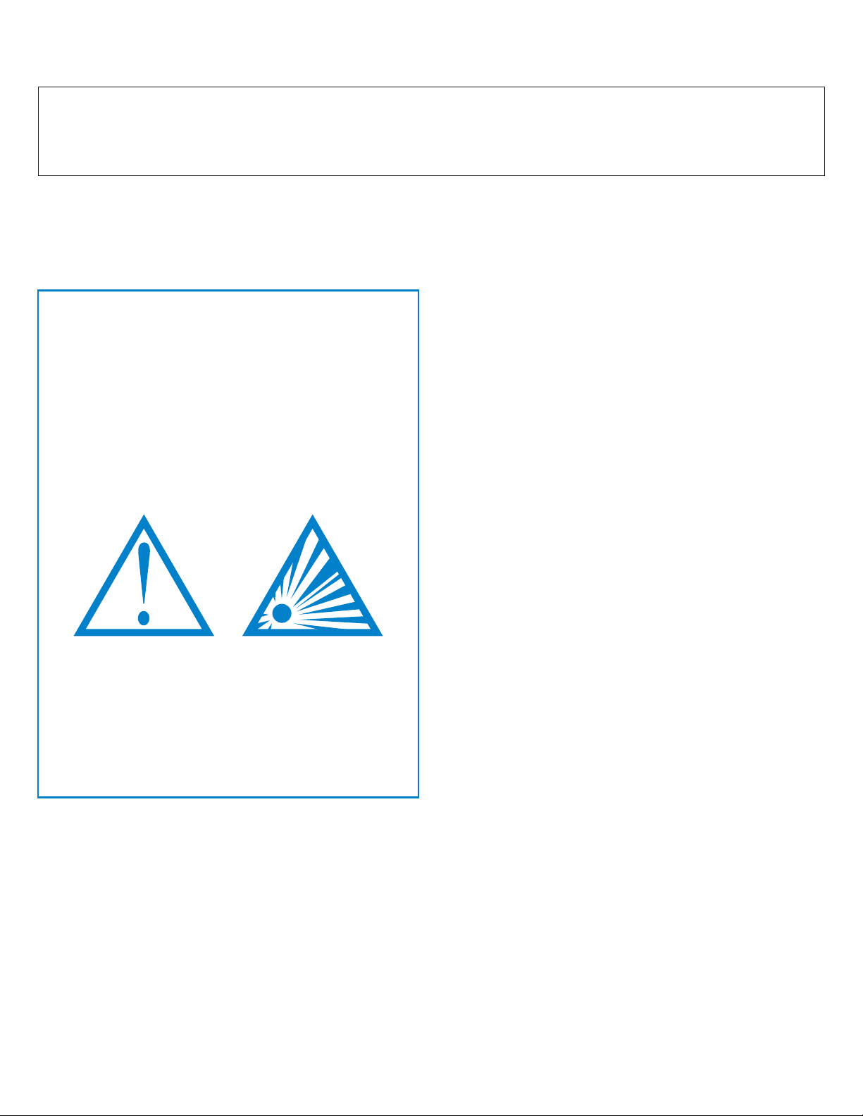
FOR YOUR SAFETY
If you smell gas:
Shut ogas to the appliance.
1
Extinguish any open ame.
2
Open lid.
3
If odor continues, immediately call
4
your gas supplier or re department.
FOR YOUR SAFETY
Do not store or use gasoline or other
1
ammable vapors and liquids in the
vicinity of this or any other appliance.
2
An unconnected liquid propane
cylinder should not be stored in the
vicinity of this or any other appliance.
FOR YOUR SAFETY: Never leave a grill unattended when in use.
Page 2

Table of Contents
Page Number
Chapte r 1 - INSTALLATION
Necessary Information . . . . . . . . . . . . . . . . . . . . . . . . . . .
Choosing a Safe Location . . . . . . . . . . . . . . . . . . . . . . . . .
Portable L.P. Gas Grills . . . . . . . . . . . . . . . . . . . . . . . . . . .
L.P. Gas Dealer Instructions . . . . . . . . . . . . . . . . . . . . . . .
Chapter 2 - ASSEMBLY INSTRUCTIONS
Step 1 ( Identifying Parts ) . . . . . . . . . . . . . . . . . . . . . . . . .
Step 2 ( Assemble Pillar to Base ) . . . . . . . . . . . . . . . . . . .
Step 3 ( Attach Grill Bottom ) . . . . . . . . . . . . . . . . . . . . . . .
Step 4 ( Side Tables , Sideburner ) . . . . . . . . . . . . . . . . . .
Step 5 ( Assemble Grill Lid ) . . . . . . . . . . . . . . . . . . . . . . .
Step 6 ( Internal Parts ) . . . . . . . . . . . . . . . . . . . . . . . . . . .
Installing an L.P. Gas Cylinder . . . . . . . . . . . . . . . . . . . . .
Connecting an L.P. Gas Cylinder . . . . . . . . . . . . . . . . . . .
Connecting to Natural Gas . . . . . . . . . . . . . . . . . . . . . . . .
4
4
4
5-7
8
9
10
11
12-13
14-17
18-19
20-21
22
23-24
25-26
Formerly:
®
Now:
CFM Corporation
2695 Meadowvale Boulevard
Mississauga, Ontario L5N 8A3 Canada
(800) 668-5323
www.cfmcorp.com
Service Note: If you are experiencing difficulties or are dissatisfied with your purchase, please contact CFM at
the telephone number listed above prior to returning your grill to the store.
Page 3
6000,7000,8000 Series Gas Grill
Installation 1Chapter
Necessary Information to
Safely Use a Gas Grill
The gas fuel used by this product is
highly flammable and must be used in
a responsible and cautious manner.
It is your responsibility to assemble,
operate, and maintain your gas
barbecue grill properly.
·
Operating this or any gas-fired appliance
in an enclosed area can produce a build-up
of carbon-monoxide, which could result in
injury or death.
2. Installation must conform with local
codes
either the National Fuel Gas Code, ANSI
Z223.1, NFPA 54 (USA), or CAN/CGA-B
149.2, Propane Installation Code (Canada)
and CAN/CGA-B 149.1 Natural Gas
Installation Code.
To check local codes, contact your local gas
dealer or gas company listed in the Yellow
Pages for recommended installation
procedures and regulations.
3. This appliance is not intended to be
installed in or on a recreational vehicle
and/or boat.
or, in the absence of local codes, with
If these instructions are ignored, there
is a possibility of a hazardous fire or
explosion which could result in proper-
ty damage, physical injury or death.
Choosing a Safe Location
for a Gas Barbecue Grill
1. The gas barbecue grill may only be used
for cooking out-of-doors.
· Do not operate this barbecue in garages,
breeze ways, sheds or any enclosed area.
4. Keep the barbecue grill at least 24
inches (61 cm) away from any combustible
construction.
·
Do not use a grill under a ceiling or cover
where the heat or flame could cause
damage.
·
Choose a level surface where the grill is
not facing directly into the wind.
·
Avoid moving the grill during use.
5. The grill area must be clear and free from
combustible materials, gasoline, and any
other flammable liquids or vapors.
·
Do not use lighter fluid or charcoal
briquettes in a gas grill. The flow of
combustion and ventilation air is not to be
obstructed. The ventilation openings of the
cylinder enclosure must be kept free and
clear from other debris. Do not store grill
covers or other items in the cylinder area.
4
Page 4
9. Make sure that the heat shield and drip
The L.P. Fuel Supply System
pan are in place under the grill bottom.
Heat and hot drippings from cooking food
·
could damage the fuel supply system.
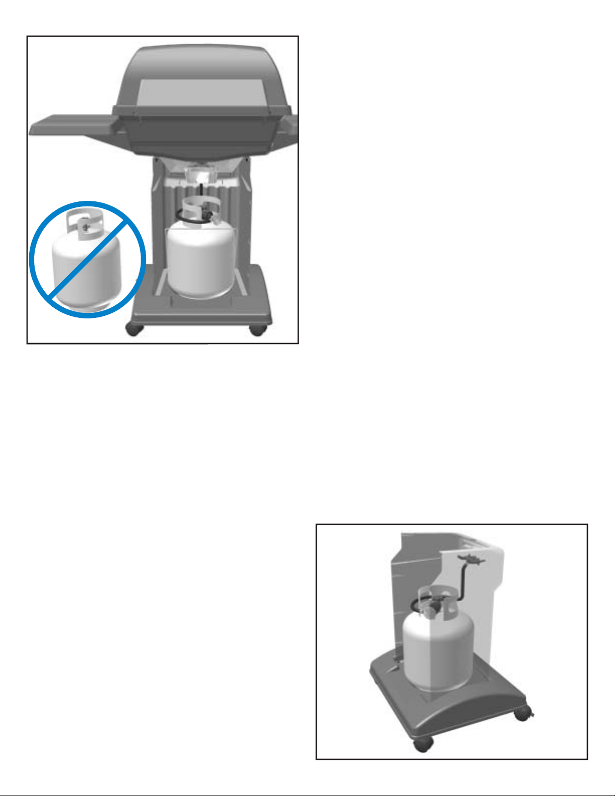
6. Do Not store a spare L.P. gas cylinder
under or near this appliance.
Do not store an L.P. cylinder in a building,
garage or any other enclosed area. Instead,
store the cylinder outdoors in a well
ventilated area, away from people and out of
the reach of children.
7. NOT FOR USE BY CHILDREN.
Place your barbecue grill in a location
·
away from children and pets.
Do not leave grill unattended when in use.
·
IMPORTANT:
unattended when in use.
NEVER leave a grill
Portable L.P. Gas
Barbecue Grills
WARNING:
appliance designed for L.P. gas. Use only
liquid propane (L.P.) gas in an appliance
designed for L.P. gas.
L.P. Gas
Liquid Propane (abbreviated L.P.) gas is
stored under high pressure inside a cylinder
and will vaporize when released. It is
important that there are no leaky connections
on the grill fuel supply system. Refer to the
Leak Testing section of this manual.
The L.P. Fuel Supply System
An L.P. gas grill requires a fuel delivery
system made up of a L.P. gas supply
cylinder, a fuel regulator with hose and a
gas-control valve.
Do not use natural gas in an
8. The outside of the barbecue grill will
become hot during use.
To avoid burns, do not touch any hot grill
·
surface. If necessary, use a protective glove
when operating control knobs, tank shut-off
valve, or lid handle.
Do not place combustible material, such
·
as cloth or plastic, on grill surface during
use.
·
Do not lean on side tables or place more
than 15 pounds of weight on a side table.
The L.P. Fuel Supply System
5
Page 5
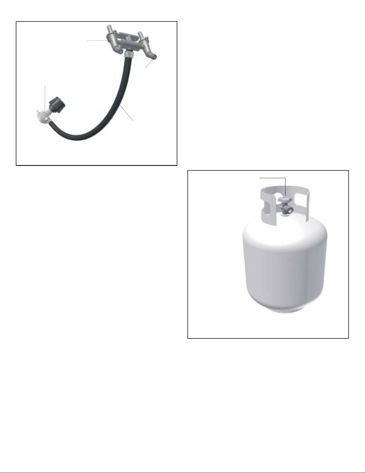
Dual Burner
Fuel-Control Valve
4. The pressure regulator and hose
assembly provided is factory set at an outlet
pressure of 11 inches water column (.4 lb.
per sq. Inch).
Type 1 Fuel
Regulator
Fuel Supply
Valve
Orifice
Hose
The L.P. Fuel Supply System
(the fuel regulator and hose)
FUEL REGULATOR AND HOSE
The fuel regulator supplied is equipped with
a Type 1 coupling nut. Do not attempt to
connect to any other L.P. cylinder not
equipped with a mating Type 1 cylinder
valve. This grill is not to be used with any
other cylinder connection device.
The fuel regulator and hose assembly with
the Type 1 fitting supplied must be used with
the appliance. Do not use a hose and
regulator assembly other than the one
supplied with the grill or a manufacturer’s
replacement fuel pressure regulator
assembly.
The Type 1 connection system has the
following features:
1. The system will not allow gas to flow until
a positive connection has been made.
2. The system has a thermal element that
will shut off the flow of gas between 240°F
and 300°F.
3. The system has a flow-limiting device
which, when activated, will limit the flow of
gas to 10 cubic feet per hour.
WARNING:
Any attempt to adjust the
regulator is dangerous and could create a
situation causing personal injury or property
damage. Consult your L.P. gas dealer if you
think the regulator is not working properly.
L.P. GAS SUPPLY CYLINDER
L.P. Cylinders can be obtained at the store
where you purchased your grill or from an
authorized L.P. gas dealer.
Cylinder Control
Valve
L.P. Gas
Cylinder
NOTE:
Some L.P.
grill models
DO NOT
include an
L.P. gas
cylinder
The L.P. Fuel Supply System
(L.P. gas cylinder)
L.P. GAS CYLINDER SPECIFICATIONS
Any L.P. gas-supply cylinder used with this
grill must be approximately 12 inches
diameter and 18 inches high.
The maximum
fuel capacity must be 20 pounds of propane.
Full-cylinder weight should be approximately
38 pounds (43.7 lbs. Nominal water
capacity).
The L.P. cylinder must have a shut-off valve
6
Page 6
terminating in a Type 1 L.P. gas-cylinder-
The heat shield in place
valve outlet. A Type 1 compatible cylinder
with a Type 1 cylinder valve has a positive
seating connection that does not permit gas
flow until a positive seal has been obtained.
The cylinder must be arranged for vapor
withdrawal. It must also include a collar to
protect the cylinder valve. A safety-relief
device having direct communication with the
vapor space of cylinder must be provided.
This will expel high-pressure gas if the
cylinder is overfilled or overheated.
All L.P. gas cylinders used with this
appliance shall be constructed and marked
in accordance with the specifications for L.P.
gas cylinders of the U.S. Department of
Transportation (DOT) or the National
Standard of Canada, CAN/CSA-B339,
Cylinders, Spheres and Tubes for
Transportation of Dangerous Goods; and
Commission, as applicable; and shall be
provided with a listed overfilling-prevention
device. Read labels on the L.P. gas-supply
cylinder.
percent full.
c.) If the information in (a.) and (b.) Is not
followed exactly, a fire causing serious injury
or death may occur.
TRANSPORTING A FULL CYLINDER
WARNING:
Handle a full cylinder with care.
Gas is under high pressure.
You should transport only one cylinder at a
time. Transport the cylinder in an upright and
secure manner with the control valve turned
off and the POL plug in place.
Do not transport a cylinder in the passenger
compartment of a vehicle.
Do not leave cylinder in direct sunlight or in
a high-heat area such as a closed car trunk.
High-heat areas could cause the relief valve
to vent gas.
Use a cylinder cap on the cylinder-valve
outlet during transport and when the cylinder
is not connected to the grill. Keep cylinder
valve closed when not in use.
DANGER:
Do not insert any foreign objects
into the valve outlet. You may damage the
back check, A damaged back check can
cause a leak, which could result in explosion,
fire, severe personal injury or death.
Allow only a qualified L.P. gas dealer to
fill or repair an L.P. gas-supply cylinder.
Inform the gas dealer if it is a new or used
cylinder to be filled. Caution the gas dealer
not to overfill the fuel cylinder.
After filling, have the gas dealer check for
leaks and that the relief valve remains free to
function.
Have the gas dealer weigh the cylinder
after filling to ensure that the cylinder is not
overfilled.
DANGER:
a.) Do not store a spare L.P. gas cylinder
under or near this appliance.
b.) Never fill the gas cylinder beyond 80
HEAT SHIELD
WARNING:
The heat shield must be
installed between the grill bottom and the
pillar.
Operating this grill without the heat shield
attached to the grill bottom would result in a
hazardous situation which could cause
serious property damage and possible
physical injury.
The heat shield in place
7
Page 7
Take These Instructions to the L.P. Gas Dealer
When using a cylinder exchange, be sure the
exchanged cylinder is a Type 1 cylinder; a 510
POL cylinder will not fit a Type 1 regulator.
FILLING AND PURGING
TYPE 1 L.P. GAS CYLINDERS
DANGER:
cylinders must be performed by personnel who
have been thoroughly trained in accepted L.P.
gas industry procedures. Failure to follow this
instruction may result in explosion, fire, severe
personal injury or death.
IMPORTANT:
filling. This tank is easily filled with a standard
CGA 510 POL filling connection.
Purging and filling of L.P. gas
Purge new cylinders before
The L.P. gas cylinder has a Type 1 cylinder
valve with a back-check module in its outlet
that will not permit gas to flow until an
evacuation device is installed. To purge the
L.P. gas cylinder, the back-check module must
be opened with an evacuation device.
PURGING AND EVACUATION DEVICES
FOR L.P. GAS CYLINDER WITH TYPE 1
CYLINDER VALVES
A. Hose-end valve with a bleed port: Purging
can be accomplished using a hose-end valve
containing a bleed port, which also allows for
evacuation without the use of an adapter.
B. Hose-end valve without a bleed port:
When a hose-end valve does not have a bleed
port, a separate device must be used for
evacuation.
CGA-510 POL
Example A
Filling a Type 1 Cylinder Valve
Example A: shows a CGA-510 POL fitting.
Example B: shows using a Type 1 POL fitting.
Type 1
(cut away to see fitting)
C. Purging using a Type 1 connection: L.P.
gas cylinder evacuation can be accomplished
during each purging by using a Type 1
connection. The Type 1 valve outlet has 15/16” external ACME right-hand thread that will
accept this connection.
CAUTION:
cylinder, do not insert a POL plug into the
valve outlet. Insertion of this plug will prevent
the back-check from closing. Use ONLY the
provided cap and strap attached to the outlet.
Close the cylinder valve knob before returning
the cylinder to the customer.
For proper purging procedures in the USA,
refer to: Safety Bulletin NPGA # 133, “Purging
L.P. Gas Cylinders,” and Safety Bulletin NPGA
#130, “Recommended Procedures for Filling
Cylinders.”
After purging or filling an L.P. gas
Example B
DANGER:
beyond 80% full. If this information is not
followed exactly, a fire causing serious injury
or death may occur.
8
Do not fill an L.P. gas cylinder
Page 8
6000,7000,8000 Series Gas Grill
Assembly Instructions 2Chapter
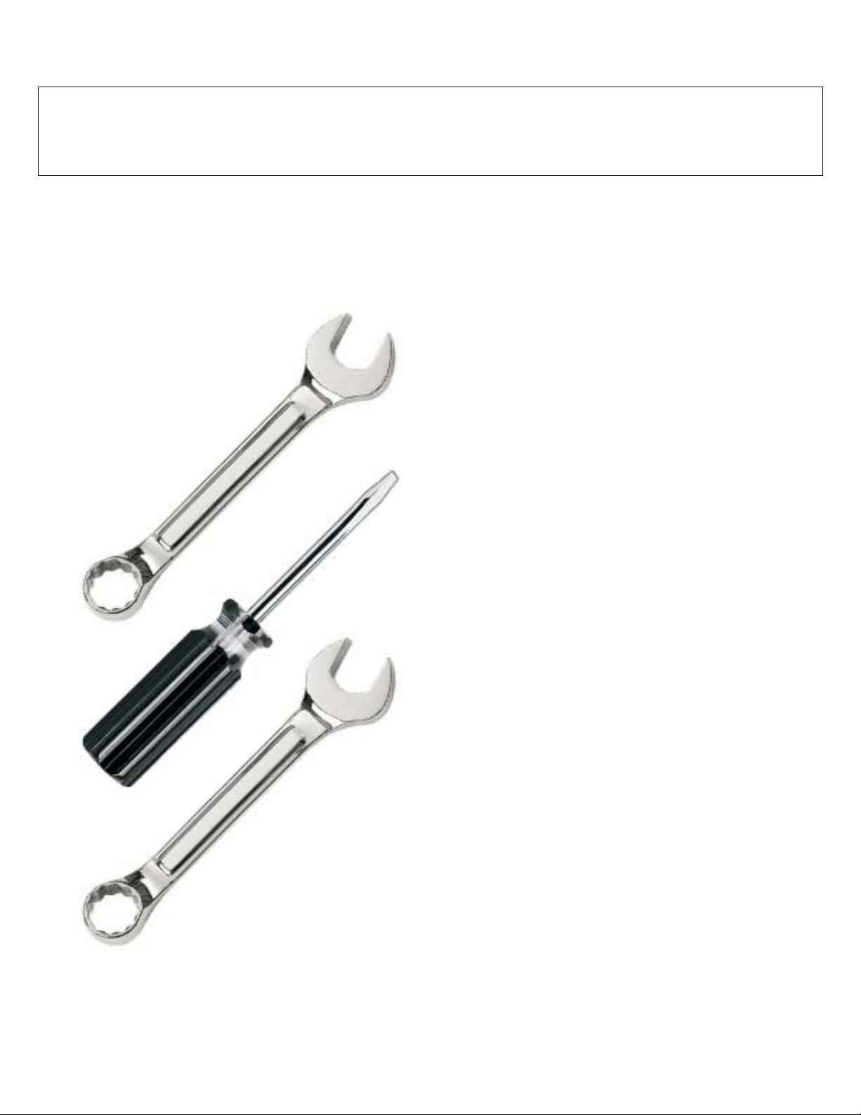
Tools needed to assemble grill:
·
flat-head screwdriver
phillips-head screwdriver
·
(For side burner equipped grills)
3/8” open-end wrench*
·
·
7/16” open-end wrench*
A socket set or an adjustable
*
wrench may be used in place
of the open-end wrenches.
3/8
Getting Started
Getting Started
1. Please follow the steps in the order that
1. Please follow the steps in the order that
they are presented.
they are presented.
2. Assemble the grill where you plan to use it.
2. Assemble the grill where you plan to use it.
3. You may want to place an old towel or
3. You may want to place an old towel or
cloth at the assembly site to prevent nuts and
cloth at the assembly site to prevent nuts and
bolts from becoming lost.
bolts from becoming lost.
4. Have a friend help. An assistant can make
4. Have a friend help. An assistant can make
the assembly easier by holding the parts in
the assembly easier by holding the parts in
place while you fasten the nuts and bolts.
place while you fasten the nuts and bolts.
5. To be ready to barbecue immediately, have
5. To be ready to barbecue immediately, have
the L.P. gas cylinder filled by an authorized
the L.P. gas cylinder filled by an authorized
L.P. dealer or cylinder exchange center.
L.P. dealer or cylinder exchange center.
Unpacking the Grill Parts
Unpacking the Grill Parts
1. Remove and set aside all inner boxes and
1. Remove and set aside all inner boxes and
parts from the master carton.
parts from the master carton.
2. Remove and set aside all wrapping paper
2. Remove and set aside all wrapping paper
and additional packaging from the parts.
and additional packaging from the parts.
3. Do not destroy carton or packing until your
3. Do not destroy carton or packing until your
grill is completely assembled and operating to
grill is completely assembled and operating to
your satisfaction.
your satisfaction.
7/16
Liquid Propane Models
Liquid Propane Models
If a L.P. gas cylinder has been included with
If a L.P. gas cylinder has been included with
your L.P. gas grill, it has been shipped empty
your L.P. gas grill, it has been shipped empty
for safety reasons. To be ready to grill
for safety reasons. To be ready to grill
immediately, please have the fuel cylinder
immediately, please have the fuel cylinder
filled with L.P. gas by an authorized L.P. gas
filled with L.P. gas by an authorized L.P. gas
dealer. Some L.P. gas grill models do not
dealer. Some L.P. gas grill models do not
include a L.P. gas cylinder.
include a L.P. gas cylinder.
Natural Gas Models
Natural Gas Models
Natural gas grills require a connection to a
Natural gas grills require a connection to a
natural gas supply. The gas connection should
natural gas supply. The gas connection should
be made only by a qualified installer or a
be made only by a qualified installer or a
licensed plumber. The gas supply line must
licensed plumber. The gas supply line must
not be installed by the consumer.
not be installed by the consumer.
9
Page 9
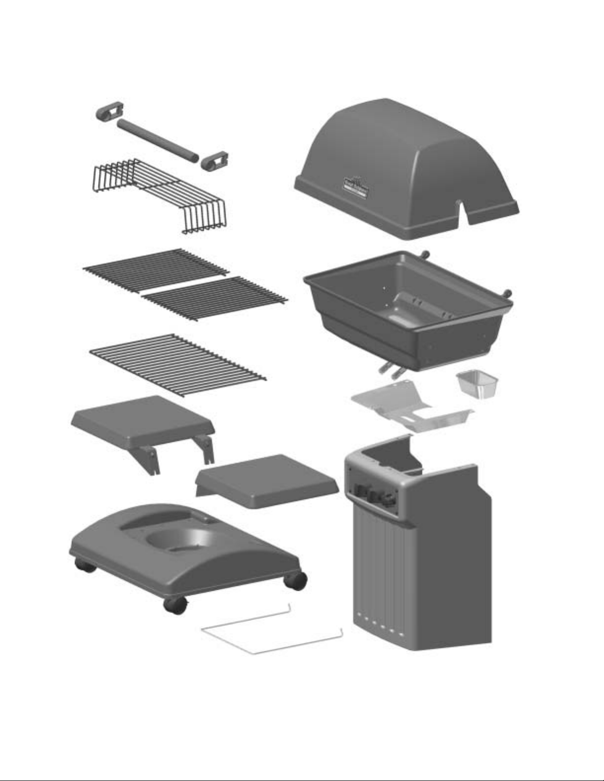
Assembly Step 1 - Identifying the Grill Parts
Locate these parts:
handle
standoff (2)
handle (1)
warming rack (1)
cooking grids
6000 series
(1)
all other models
rock grate (1)
grill lid (1)
grill bottom
assembly (1)
(burner
assembly
Installed)
(2)
grease pan (1)
side table (2)
base (1)
(2 locking casters and
2 non-locking casters
Installed)
cylinder retainer
wire (1)
Not Pictured:
ceramic briquettes (1 pkg)
master hardware bag (1)
(consisting of 1 each of A,B,C,D bags)
heat shield (1)
pillar (1)
(knobs, ignitor,
valve, hose with
regulator installed)
NOTE:
Not all models feature identical parts. Some components may differ,
but the functions and assembly are similar. Refer to the replacement
part listing in Chapter 3 for your model’s components.
10
Page 10
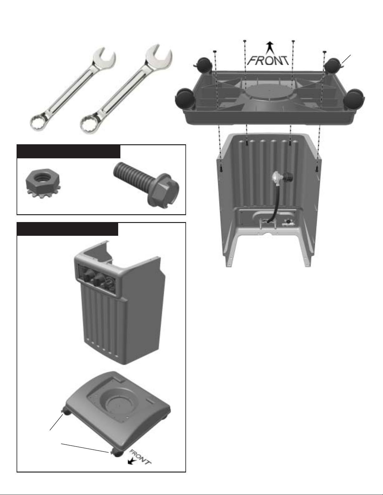
Assembly Step 2 - Attach the Base to the Pillar
Tools Needed:
3/8”
wrench
USE HARDWARE BAG A :
1/4-20 hex
nut (4)
1/4-20 x 3/4”
bolt (4)
locking
caster
7/16”
wrench
back side of base,
upside down
LOCATE THESE PARTS:
pillar
assembly (1)
base assembly (1)
back side of pillar,
upside down
1.
Lock the pre-assembled casters on base by
pushing down on the latch.
2.
Set the pillar upside down.
3.
Set the base upside down onto the pillar
bottom as shown, aligning the holes in the
base with holes in the pillar.
Insert the four bolts through the holes in the
4.
pillar and base. Thread the locking hex nuts
onto bolts. Tighten the bolts and nuts with the
wrenches.
locking
casters
11
Carefully turn the assembly upright onto the
5.
casters.
Page 11

Assembly Step 3 - Attach Grill Bottom to Pillar
Tools Needed:
3/8”
wrench
USE HARDWARE BAG B :
1/4-20
nut (4)
1/4-20 x 1”
bolt (4)
LOCATE THESE PARTS:
back side of grill
7/16”
wrench
grill bottom
assembly (1)
heat
shield (1)
12
1.
Working from the back (open) side of the pillar,
set the heat shield on top of the pillar.
2.
Set the grill bottom on top of the heat shield. Line
up the burner tubes with the control valve orifices
inside the pillar. Adjust the grill bottom and heat
shield to line up the bolt holes.
3.
Insert the bolts through the grill bottom and
tighten the nuts from inside the pillar.
Page 12

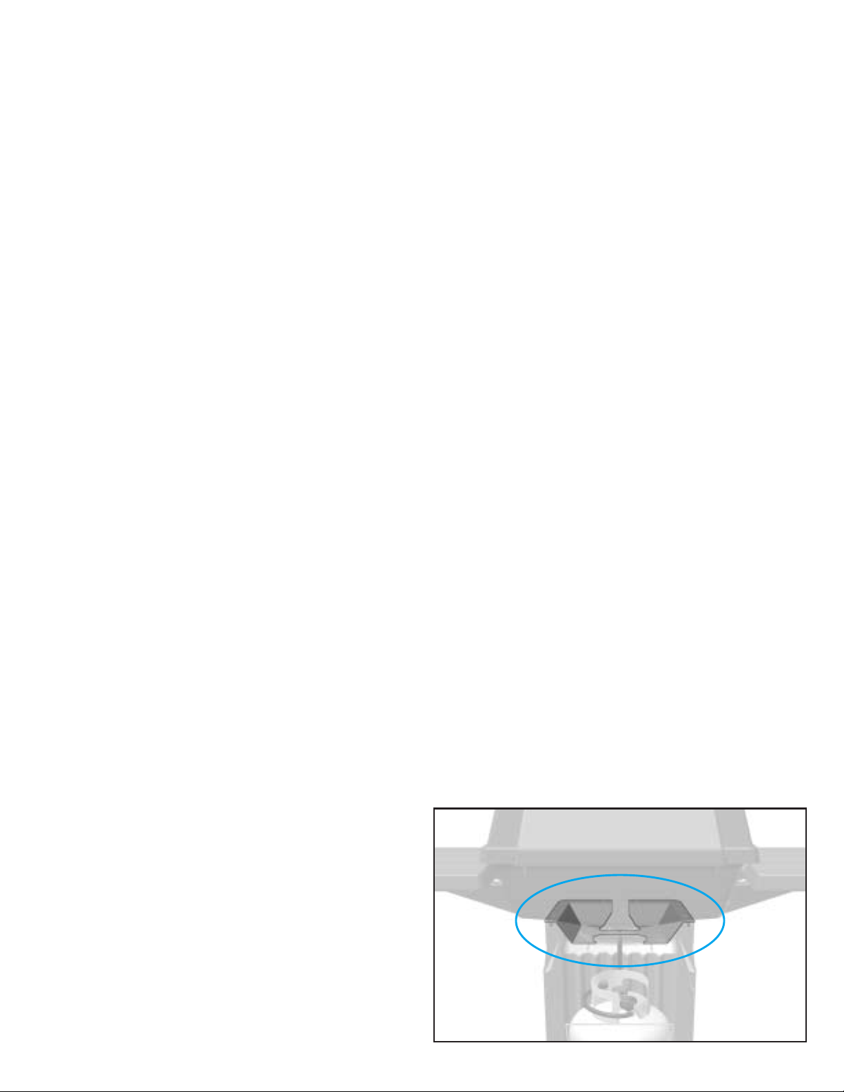
IMPORTANT: Make sure the
control valve ends are properly
seated inside the burner tubes as
shown.
(The control valve ends
are attached to the pillar; the
burner tubes are attached and
extend through the grill bottom.)
Assembly Step 3 - Continued
Improper installation and
connection of the burner tubes to
the control valves is dangerous
and may lead to damaging fire
and personal injury.
Locate the two black igniter
4.
wires beneath the grill bottom.
Press the metal contacts of
the loose ends of the wires
onto the metal pins of the
igniter unit. The position of the
wires is not relevant - either
wire may be connected to
either prong. It is important
that the wires are connected
securely.
This illustration shows a proper
connection.
Venturi
Z
Valve
13
Page 13

Assembly Step 4 - Attach the Side Tables
Tools Needed:
wrench
3/8”
7/16”
wrench
USE HARDWARE BAG C :
1/4-20 hex
nut (8)
LOCATE THESE PARTS:
1/4-20 x 3/4”
bolt (8)
side table (2)
NOTE: For grill models equipped
with a side burner, only the right side
table will be installed. Refer to the
instructions on the following pages
for side burner installation. Retain 4
nuts and 4 bolts from hardware bag
C to be used for the side burner.
14
1.
Insert the 3/4” bolts
through the holes in
the support brackets
of the side table.
2.
Attach the side table
to the four holes
located in the side of
the grill bottom using
the locking hex nuts
provided.
3.
Attach the opposite
side table the same
way.
Page 14

Side Burner Installation
Only for grills equipped with a side burner
LOCATE THESE PARTS:
side burner
table (1)
The side burner installs in place of the left
side table - attaching the side burner is the
same as attaching a side table. You will use
the bolts and nuts from hardware bag C,
used in Step 4.
For side burner equipped models:
Insert the 3/4" bolts (from hardware bag
1.
C) through holes in the support arms of
the side burner table.
2.
Attach the side burner table to the four
holes located in the LEFT side of the grill
bottom using the locking hex nuts
provided.
3.
Firmly tighten the nuts and bolts using a
flat head screwdriver and a 7/16” wrench.
15
Page 15

Tools Needed:
Side Burner Installation - Continued
Only for grills equipped with a side burner
4.
Working below the side burner table,
loosen the two screws that secure the
brass burner.
Phillips head screwdriver
LOCATE THESE PARTS:
single burner
control valve
(attached to
hose/valve/regulator
inside pillar)
hardware bag
containing knob (1)
and M4-.7x10
screws(2)
The burner tube should move freely - this
is to allow space to install the side burner
valve.
5.
Locate the side burner valve / hose that is
connected to the main valve / regulator /
dual hose assembly.
HINT
: The main valve is already attached
inside the pillar.
6.
Route the burner valve from behind the
pillar to the side burner.
16
Page 16

Side Burner Installation - Continued
Only for grills equipped with a side burner
igniter electrode has
been omitted for clarity
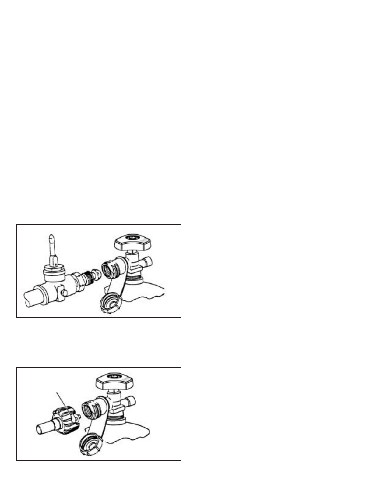
7. Insert the knob stem through the
mounting hole in the control panel from
the back side.
valve orifice properly
seated into burner tube
8. Insert the orifice end of the control valve
into the burner tube.
IMPORTANT: The valve orifice must seat
properly into the burner tube.
9. Replace and tighten the screws that
secure the brass burner.
17
10.
Insert and tighten the screws through the
front of the control panel to secure the
control valve.
11.
Attach the burner control knob.
Page 17

Assembly Step 5 - Assemble the Grill Lid
Tools Needed:
flat-head
screwdriver
7/16”
wrench
LOCATE THESE PARTS:
handle (1)
handle
standoff (2)
USE HARDWARE BAG D :
1/4” x 1-1/8”
hinge pin (2)
hairpin (2)
1/4-20 hex
nut (4)
1/4-20 x 5/8”
bolt (4)
standoff
gasket (2)
grill
lid (1)
1.2.Position the back of the lid so that the rear
holes are in line with the hinge struts on the
back of the grill bottom.
Gently set the grill lid onto the grill bottom.
18
Page 18

Assembly Step 5 - continued
5
3
4
Hold the lid to align the hinge holes.
3.
Insert a hinge pin through the hinge hole
4.
in the lid and into the hole in the bottom
hinge strut.
5.
After the hinge pin is in place, insert a
hair pin through the hole of the hinge pin
to secure it.
HINT: There is an air space between the
back of the lid and the grill bottom where
you can install the pins.
6.
Repeat for the
opposite side.
standoff
5
4
3
standoff
gasket
grill lid
7.
Raise the lid to attach
the front handle.
8.
Attach one handle
standoff to the front
of the grill lid, as shown.
9.
Insert one end of the handle into the
hole of the mounted standoff.
10.
Place the other standoff onto the handle,
and while holding the handle in place,
assemble the opposite standoff to the lid
in the same manner.
19
Page 19

Assembly Step 6 - Installing the Internal Grill Parts
Place the single rock grate into the grill
bottom.
Open
the package containing the
ceramic
briquettes and place them on
the
rock grate.
No Tools are Needed.
LOCATE THESE PARTS:
rock grate
(1)
ceramic
briquettes
(1 package)
cooking grids
6000 series (1)
all other models (2)
1.
Place the single rock grate into the grill
bottom.
warming rack
(1)
20
2.
Open the package containing the
ceramic briquettes and place them on
the rock grate.
Page 20

Assembly Step 6 - continued
3. It is important to properly arrange all
the ceramic briquettes onto the rock
grate to allow for good air flow during
use.
NOTICE THE SPACING:
The proper amount of briquettes are
5
supplied and there is no need to add
more. Some space between the
briquettes is necessary.
4.
Set the porcelain coated cooking
grids, side by side, on the front and
back ledges formed inside the grill
bottom for a level cooking surface.
(6000 series grills are equipped with one large
single cooking grid in place of the 2 grids)
5.
Set the warming rack onto the back
of the cooking grids.
21
Page 21

1
2
3
4
Items Needed:
Installing an L.P. Gas Cylinder
Obtain a filled L.P. gas cylinder. Read and
follow all directions on the cylinder and fuel
hose safety tags.
L.P. Gas Cylinder
(1 FILLED)
NOTE: Some
L.P. grill models
DO NOT include
an L.P. gas
cylinder
LOCATE THESE PARTS:
cylinder retainer
wire (1)
grease drip
pan (1)
WARNING:
grill outdoors only.
1.
Working from behind the grill, set the
cylinder into the large round opening in
the grill base.
2.
Position the cylinder-retainer wire around
the cylinder collar as shown.
3.
Insert the right end of the wire into the
small opening in the base.
4.
Flex the left side so that it fits into the
opposite opening on the left side of the
base.
Connect the L.P. cylinder to the
2
1
(Back side, under grill bottom)
22
3
4
Page 22

Connecting the L.P. Gas Cylinder
Install a Drip Pan in the Heat Shield
The grease pan is a 3-1/2”x6” aluminum loaf
pan
available at most grocery stores.
Connecting the Regulator to Cylinder
1. The top knob on the supply cylinder must
be closed. See that the top cylinder knob is
turned clockwise to a full stop.
2. Check that all the grill burner knobs are
turned off.
7. Make sure the hose has no kinks or
sharp bends and clears any areas that will
become hot during use. Never put strain on
the hose where it joins a fitting. The rubber
fuel supply hose must not touch the bottom
grill casting during use.
8. Before lighting grill, check all connections
for leaks using a mild soapy-water solution.
9. Place an aluminum 3-1/2” x 6” loaf pan
into the opening in the heat shield located
beneath the grill bottom. During use the pan
will catch hot grease drippings that could
damage the fuel supply system.
3. Remove the protective caps from the
cylinder valve and coupling nut, if present.
4. Hold the regulator in one hand and insert
the nipple into the valve outlet. Be sure the
nipple is centered in the valve outlet. The
coupling nut connects to the large outside
threads on the valve outlet. Use care not to
cross thread the connection.
5. Hand tighten the coupling nut clockwise
until it comes to a full stop. Tighten by hand
only. Do not use tools.
6. CAUTION: In the connection process,
the grill side of the connection will seal on
the back check in the valve, resulting in a
slight resistance. The connection requires
about one-half to three-quarters additional
turn to complete the connection.
(Back Side, Under the Grill Bottom)
Grease
Drip Pan
Heat
Shield
NOTE: If you cannot complete the final
connection, disconnect the regulator and
repeat steps 4 through 6. If you are still
unable to complete the connection, do not
use this valve and regulator.
23
Install a Drip Pan in the Heat Shield
The grease pan is a 3-1/2”x6” aluminum loaf
pan available at most grocery stores.
Page 23

L.P. Gas OnlySide Burner Option -
Working from behind the grill:
1. For grills equipped with a side burner,
connect to an L.P. gas supply cylinder as
directed on page 23 and 24 of this manual.
2. Secure a fuel supply cylinder with a tank
retainer wire as directed on page 22.
3. Make the L.P. gas cylinder connection as
instructed on the previous page.
The illustration above shows a side burner
with fuel supply system correctly installed.
Perform a leak test to all connections as
described in the “Leak Test” section on page
28.
The side burner option is only available for
L.P. gas model grills only. Grills equipped
with a side burner are not designed for safe
use with natural gas connections.
24
Page 24

Natural Gas Grills - Connecting to Natural Gas
(for specially equipped natural gas grills only)
DANGER:
If the appliance is for connection to natural
gas, the gas connections should be made by a
qualified installer or a licensed plumber. The
gas-supply line must not be installed by the
consumer.
The valve-orifices and fuel supply hose
system necessary for use with natural gas is
different than the system required for L.P. gas.
Modification to the burner valve/orifices allow
the use of natural gas. An L.P. cylinder is not
needed.
WARNING:
gas in an appliance designed for natural gas.
Use only natural gas in an appliance designed
for natural gas.
INSTALLATION FOR NATURAL GAS
EXPLOSIVE AND FLAMMABLE!
Do not use liquid propane (L.P.)
A quick-connect coupling sleeve with 3/8”
female end is provided. Install the connector
socket at the pipe end, after the shut-off valve.
This must be installed where the grill will be in
use.
It is important to observe the safety
guidelines for choosing a safe location. The
gas supply must be shut off prior to installation
of the quick connector socket. Use only a
matching factory authorized quick-connect
plug with the quick-connect socket.
Natural-gas units are equipped with a 12footlong quick-connect fuel hose in place of
the shorter hose/regulator attached to the
burner valve.
Dust Cap
The maximum inlet supply pressure is 11.0"
w.c. for propane gas and 7.0" w.c. for natural
gas.
The specified supply pressure is 11.0" w.c.
for propane gas and 7.0" wc. for natural gas.
The piping system should be installed by a
qualified service technician in accordance with
the National Fuel Gas Code (NFPA 54/ANSI
Z223.1) in the U.S.A., including:
1. The appliance and its individual shut-off
valve must be disconnected from the gassupply piping system during any pressure
testing of that system at test pressures in
excess of 1/2 psi (3.5 kPa).
2. The appliance must be isolated from the
gas-supply piping system by closing its
individual manual shut-off valve during any
pressure testing of the gas supply piping
system at test pressures equal to or less than
1/2 psi (3.5 kPa).
Shut-off Valve
Connector Socket
One example of an Individual Shut-Off
Valve with the
Prior to inserting, turn on gas supply and test
all connections with an ammonia-free soap
and water solution. Apply this solution to the
stem of the shut-off valve and opening of the
socket to detect leaks. (See Leak Testing
Natural Gas Connections on the following
page).
Quick-Connect Socket.
Gas Flow
5
25
Page 25

Natural Gas Grills - Connecting to Natural Gas
(for specially equipped natural gas grills only)
OPERATING THE QUICK-CONNECT
Follow all directions on tags attached to hose.
1. To connect the fuel-supply hose to the fuel
supply, the shut-off valve must be closed.
2. Remove the dust cap from the connector
socket by sliding the connector sleeve back to
release the plug. Remove the dust cap from
the plug.
Supplied
With Grill
Plug
3. Position the plug end of the fuel supply
hose into the sleeve opening.
Not Supplied
With Grill
3/8” NPT
Fitting
5. Push the plug into the connector until the
sleeve snaps forward to lock the fitting in
place. Turn on the shut-off valve. The flow of
gas to the appliance will be restricted if the
plug is not connected properly.
6. Test for gas leaks using an ammonia-free
soap and water solution.
TO DISCONNECT THE FUEL SUPPLY
1. Pull connector sleeve back and pull plug
out of socket. This will automatically shut off
gas to the appliance.
2. Close the shut-off valve and install the dust
caps on the socket and plug. Always turn off
the fuel supply at the shut-off valve when the
grill is not in use.
LEAK TEST CONNECTIONS
Test all the fuel supply connections using an
ammonia-free soap and water solution equally
mixed. Never use fire to test for leaks.
To Grill
Connector Sleeve
4. Slide the connector sleeve back, firmly
push the fitting into the connector.
Shut-off Valve
To House
Dust Cap
1. Turn on the gas shut-off valve.
2. Coat all connections of the fuel supply
system, especially at the quick-connect.
3. Watch for bubbles to indicate a leak.
4. If there is a leak, shut off the gas supply
and re-connect the hose to the socket. Re-test
for leaks.
Do not use the grill if a leak is detected that
cannot be corrected in this manner or if the
hose and connections become damaged.
Replace damaged components with only
factory authorized parts.
Do not strain or kink the fuel-supply hose.
See that the hose is kept clear of surfaces that
become hot during use.
26
Page 26

6000,7000,8000 Series Gas Grill
Use and Care Directions 3Chapter
Z
Leak Testing the
Z
Z
Z
Z
Z
Z
Fuel Supply System
Z
Lighting Instructions
Replacement Parts
27
Page 27

Leak Testing
DANGER
To prevent fire or explosion hazard:
· Do not smoke while performing a leak
test.
· Do not permit any sources of ignition
in the area when testing for leaks.
· Perform leak tests outdoors only.
· Never perform a leak test near a fire or
lame.
f
How to Check the Fuel Supply System for
Gas Leaks
1. Mix a solution of equal parts mild
detergent or liquid soap and water.
2. Turn off the burner control knobs.
3. Turn the top knob of the fuel-supply
cylinder counterclockwise one rotation to
open.
4. Apply the soap solution to all connections
of fuel-supply assembly.
Perform a leak test each time the gas
supply cylinder is connected to the regulator.
Leak test any time a part of the gas system
is replaced. Perform a leak test at least once
each year whether the L.P. gas supply
cylinder has been disconnected or not.
Have a dealer check the cylinder for
deterioration after 10 years, according to
DOT regulations. Immediately replace
cylinder if any is found.
IMPORTANT! Inspect the gas supply hose
regularly. If there are cuts, excessive
abrasion or wear, replace the hose prior to
operating the appliance.
Use only the hose replacement specified in
the parts list for your grill.
Z
If no soap bubbles appear, the grill is fine
for use.
If bubbles form at the connections, there is
a leak. In case of a leak, try tightening the
joint. If necessary, replace the faulty part with
a replacement part recommended by the
manufacturer.
5. Turn off the knob on fuel-supply cylinder.
6. Turn on the burner control knobs for a
moment to release pressure in hose, then
turn the control knobs back off.
7. Wash off soapy solution with cold water
and towel dry.
WARNING: Do not attempt to repair the
cylinder valve. If it becomes damaged,
the cylinder must be replaced.
If you are unable to stop a leak, shut off the
gas supply at the cylinder valve. Remove the
cylinder from the grill. Call a gas appliance
serviceman or L.P. gas dealer. Do not use
appliance until the leak is fixed.
Z
Z
Z
Z
Z
Z
Leak Testing the
Fuel Supply System
(arrows denote primary
areas to check)
Z
Z
Z
Z
Z
28
Page 28

Lighting Instructions
IGNITER LIGHTING SYSTEM
The Igniter System consists of an igniter unit,
a gas-collector box, one ceramic electrode,
and lead wires. Gas is collected in the metal
collector box located at the burner. When the
igniter knob is turned, an electric spark is
created at the ceramic electrode. The gas is
then ignited by the spark.
To test: Watch the electrode tip inside the gas
collector while activating the igniter. To avoid a
possible shock, do not touch the burner or
metal parts on igniter system while performing
igniter test. A visible spark should jump from
the electrode. The spark gap is set when the
electrode is installed.
If there isn't a spark, check the lead wires
and connections. The igniter wires should be
kept away from the grill bottom. Also check
that the ceramic electrode in the collector box
is not broken.
Sometimes dirt and rust at and around the
electrode can prevent an igniter spark. Clean
them with a degreaser or warm soapy water,
and dry. Remove rust from electrode tip and
metal surfaces by lightly sanding with an
emery cloth or fine-grain sandpaper.
CAUTION: Do not stand with head or arms
over the grill.
STEP 5. To light using the igniter:
Push in and turn the right burner-control knob
counter-clockwise to the high setting.
STEP 6. Immediately turn the igniter knob
clockwise until you hear it click. Repeat 4 to 5
times if necessary.
The burner should light.
STEP 7. If the burner fails to light properly,
turn the burner control knob off. Also turn off
the L.P. cylinder knob. Wait five minutes before
attempting to light the burner again. This will
allow time for released gas to disperse.
HINT: If the burner does not light after trying
again, turn off burner-control knob, the L.P.
cylinder knob and try match lighting the grill
once the gas has cleared.
LIGHTING INSTRUCTIONS
(Read all the steps before beginning.)
STEP 1. Check the burner venturi tubes for
blockage from an insect nest (see,
“CLEANING THE BURNER VENTURI
TUBES”).
STEP 2. Ensure that both of the burnercontrol knobs are in the OFF position.
STEP 3.
WARNING: Attempting to light the grill with
the lid down could cause an explosion.
STEP 4. Go behind the grill and turn on the
fuel supply valve. One counter-clockwise turn
is generally enough to open the valve.
OPEN GRILL LID
Operating the Control Knobs
Gas control knobs PRESS IN and rotate
counterclockwise.
TURN THE IGNITER KNOB CLOCKWISE
UNTIL IT CLICKS. Do NOT turn the igniter
knob counter-clockwise because it will strip the
knob and become unuseable.
29
Page 29

Lighting Instructions
MATCH LIGHTING
IMPORTANT: The match lighting hole is
found under the front right corner of the grill
bottom. When match lighting the grill, use the
gas control knob on your RIGHT-HAND side
(closest to the match lighting hole).
Repeat steps 1 to 4 of “Igniter Lighting
Instructions.”
STEP 5. To match light: push down and turn
the RIGHT burner control knob
counterclockwise to the high setting.
STEP 6.
IMMEDIATELY strike a long wooden match
and position the burning match through match
lighting hole in the grill bottom. Extend the
flame near a burner port in the bottom edge of
the burner. The burner should light.
To light the other side of the burner, press in
and turn the opposite control knob. The flame
will track around the burner. Allow grill to
preheat with the grill lid closed for five to ten
minutes before cooking.
CAUTION: Do not touch any hot grill parts.
The outside of the grill bottom becomes very
hot during use. It may be necessary to use
protective gloves.
HOW TO SHUT OFF THE GRILL
STEP 1. Turn the burner-control knob(s) off.
The burner flame will go out.
STEP 2. Turn off the top L.P. cylinder valve
by turning the knob in a clockwise direction
until it stops.
IMPORTANT: Always have the gas shut off at
the L.P. cylinder valve when the grill is not in
use. The L.P. cylinder has a leak detection
feature which will restrict the amount of gas
flow to the burner if the tank shut-off valve has
not been turned off prior to the next use.
Locating the Match Lighting Hole
The match lighting hole is located beneath the
lower right corner of the grill bottom casting.
30
Page 30

Long detachable power-supply cords or
extension cords can also be used with care. The
marked electrical rating of the cord set or
extension cord should be at least as great as the
electrical rating of the appliance. If the appliance
is of the grounded type, the extension cord
should be a grounding-type 3 wire cord. Use
outdoor extension cords with a surface marked
with sux letters “W-A” and with a tag stating
“Suitable for Use with Outdoor Appliances.”
Keep the connection to an extension cord away
from water and othe ground. Arrange the cord
so that it will not drape over the counter top or
tabletop where it can be pulled or tripped over.
Do not clean any electrical product with a water
spray or the like. Store electrical products
indoors out of reach of children when not in use.
6000,7000,8000 Series Replacement Parts
Replacement parts are available direct from our warehouse. Some components are not available
preassembled and may be ordered separately. For convenience, the following parts list is provided
along with a representation of the items listed. Charges for replacement parts and shipping may
apply.
www.cfmcorp.com or call 1.800.668.5323
For warranty replacements, proof of ownership and date of purchase is required. Please visit
Parts Enclosed
quantity
1
1
4
4
1
4
4
1
8
8
1
2
2
4
4
2
description
Main Hardware Bag
Hardware Bag “A”
1/4 x 20 x 3/4” Bolt
1/4 x 20 Hex Keps Nut
Hardware Bag “B”
x 20 x 1” Bolt
1/4
1/4 x 20 Hex Keps Nut
Hardware Bag “C”
1/4 x 20 x 3/4” Bolt
1/4 x 20 Hex Keps Nut
Hardware Bag “D”
1/4 x 1-1/8” Hinge Pin
Hairpin
1/4 x 20 x 5/8” Bolt
1/4 x 20 Hex Keps Nut
Handle Gasket
part no.
AM000505
AM000105
AM000904
AM000106
AM000904
AM000105
AM000904
AM000908
AM000909
AM000207
AM000904
AM000704
Parts Enclosed
quantity
2
1
1
2
1
1
L.P. Gas Models only
1
1
Preassembled Components
1
1
1
1
description
Aluminum Side Tables
Warming Rack
Lid Handle
Handle Stando
Heat Shield
Aluminum Drip Pan
L.P. Gas Cylinder
Cylinder Retainer
Base Assembly
Pillar Assembly
Grill Bottom/Burner Assembly
Side Table Assemblies
part no.
P X000505
AF000303
AP000102
AZ000802
AI000204
AI000302
AW000202
Wire
(see following pages)
AF000402
Page 31

Model 6100 Series Components
6000 Series Parts
quantity
1
1
1
1 pkg
BOTTOM / BURNER ASSEMBLY
1
consisting of:
1
1
1
8
1
1
2
Bottom / Burner Assembly
description
Grill Lid
Rock Grate
Cooking Grid
Ceramic Briquettes
Cast Brass Burner
Venturi Tube
Venturi Gasket
#8-32 x 1/2” Screw
Bottom Grill Casting
Collector Box
Collector Box Wire 8”
PILLAR ASSEMBLY
part no.
PX000105
AF000203
AF000104
AQ000103
AZ001504
AZ000505
AM000503
AM000603
PX000205
AN000103
AN000203
1
consisting of:
1
4
1
2
1
1
2
1
Natural Gas Model only:
1
1
consisting of:
1
2
2
Pillar Assembly
Aluminum Pillar (Green)
10-24 x 3/8” Screw
Printed Control Plate
10-24 x 1/2” Bolt
LP Valve / Regulator / Hose
Rotary Igniter Kit
Control Knob
Igniter Knob
Natural Gas Valve / Hose
(Replaces LP HVR AL000104)
BASE ASSEMBLY
Base Assembly
TM
ROC Base
Locking Caster
Non-Locking Caster
PXG00305
AM000203
AI000103
AM000103
AL000104
AN000303
AZ000703
AZ000603
AL000204
AH000402
AH000104
AH000105
36
Page 32

Sideburner Components
For Models with Sideburner Option Only
quantity
1
description
Sideburner Assembly
part no.
AZ001506
(Replaces 1 Side Table)
1
LP Valve / Regulator / Hose
7500 model
8500 model
AL000105
AL000106
(Replaces single hose HVR)
Variable Components
Some models may be alternately equipped the following components
TM
ROC SIDE TABLE ASSEMBLIES - Square style
(Replaces both aluminum side tables)
1
1
1
1
4
1
1
1
1
4
Right Side Table Assembly
Right Side Table
(w/hooks)
R.H. Table Bracket
L.H. Table Bracket
Screws
Left Side Table Assembly
Left Side Table
(w/cup holders)
R.H. Table Bracket
L.H. Table Bracket
Screws
AH000403
PI002001
PI002002
AM000206
AH000404
PI002001
PI002002
AM000206
TM
ROC SIDE TABLE ASSEMBLIES - Wing style
(Replaces both aluminum side tables)
1
1
1
1
4
1
1
1
1
4
1
8
2
2
Right Side Table Assembly
Right Side Table
(w/hooks)
R.H. Table Bracket
L.H. Table Bracket
Screws
Left Side Table Assembly
Left Side Table
(w/cup holders)
R.H. Table Bracket
L.H. Table Bracket
Screws
ALUMINUM BASE ASSEMBLY
(Replaces ROC base)
TM
Cast Aluminum Base
1/4-20 x 1/2” Bolt
Locking Caster
Non-locking Caster
AH000408
PI002001
PI002002
AM000206
AH000407
PI002001
PI002002
AM000206
PX000405
AM000303
AH000103
AH000203
TM TM
ROC = Rugged Outdoor Composite
39
 Loading...