

Page 1

Gasket Kit #4322
Installation Instructions
for use on the
Defiant Stove
Vermont Castings’ stoves use a rope-type gasket to
make a seal between some parts. With use, this gasket
can become compressed and begin to lose its effectiveness. It should then be replaced.
This kit includes materials to re-gasket a Model #1910
or #1945 Defiant stove. This stove model has glass
panels in the front doors. This kit is not appropriate for
the 1975-1988 model Defiant stoves which do not have
glass panels in the front doors.
Contents
• 3.5’ of 5/16” Glass Fiber Gasket for the damper
• 7’ of 3/16” Glass Fiber Gasket (Glass)
• 4¹⁄₂’ of 5/16” Wire Reinforced Glass Fiber “Armaseal”
for the griddle
• 10.9’ of 3/8” Glass Fiber Gasket for the ash door and
main doors
• 3 oz. Tube of Gasket Cement
Tools Required
Phillips screwdriver
Utility knife or scissors
Wire brush
Small cold chisel
Rubber mallet, or hammer and wood block
Flashlight or droplight
Installation Precautions
Be sure the fire is out and the stove has cooled before
replacing the gasket, and be sure to follow the standard
safety procedure for working with dusty materials: Wear
safety goggles and a dust mask.
Installation Instructions
Gaskets provide a tight seal between moving parts.
Eventually these gaskets will become compressed and
will no longer seal properly. Replacing the gaskets will
improve performance. For a guide to each gasketed
area, refer to the following sections and illustrations.
Regardless of its location, replacing a gasket involves
these steps:
1. Remove the existing gasket by scraping it out of its
channel with an old screwdriver.
2. Clean the gasketing channel with a wire brush. Be
careful with adjacent surfaces, especially if they are
enamelled. Remove any stubborn deposits with a
small cold chisel. Clean both mating surfaces thoroughly to bare metal.
3. Cut the appropriate size gasket to length, allowing
an extra inch.
4. Knead the tube of cement before opening, to mix the
contents thoroughly.
5. Place an unbroken 1/8” bead of gasket cement in
the channel. Do not use too much cement as it may
saturate the gasket; the gasket must remain soft
and resilient. One tube of cement will produce a 1/8”
bead sufficient for all the gasket in this kit.
6. Starting with one end, press the gasket into the
cemented channel. If the gasket goes around and
meets itself, ensure that you have a good joint before trimming the excess gasket. Do not overlap or
leave ragged edges.
7. Seat the gasket by placing it firmly against its normal
mating surface. A slip of waxed paper between the
gasket and its mating surface will help keep the cement from traveling through the gasket and sticking
to the mating surface. Clean away any excess cement.
8. With enamel stoves, be careful to keep cement off
the enamel finish. If cement does accidentally get on
the enamel, wash it off immediately with warm water.
9. Allow to dry. Be sure to remove the waxed paper!
10. If you have questions, refer to the Defiant Owner’s
Manual, or a Vermont Castings Dealer.
Griddle
Remove the griddle. Pull off the old gasket and clean
the channel with the wire brush. Set the steel reinforced
5/16” gasket in the griddle channel and mark the correct length. Place the gasket on a wood cutting surface
and trim with a utility knife or scissors. Twist the ends
slightly to prevent unraveling. Place a continuous 1/8”
bead of gasket cement in the channel and press the
gasket into place. Replace the griddle and compress
against the gasket by striking around the edges with
the rubber mallet or hammer and block of wood. Do not
strike the stove top.
2003144 8/08 Rev. 6
Page 2
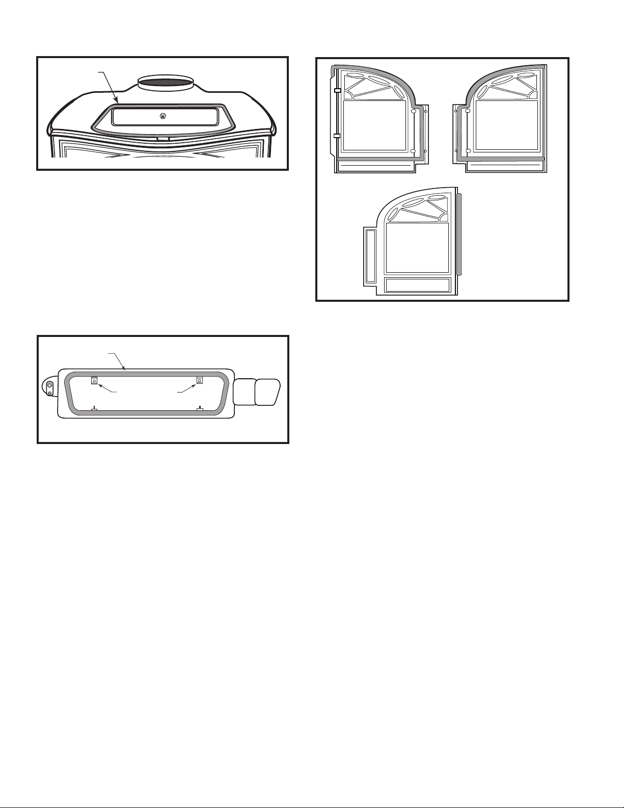
Gasket
KT314
Fig. 1 Griddle gasket.
Ash Door
You may find it helpful to remove the ashpan bracket
from the inside ashdoor; use a 7/16” wrench for this.
Remove the old gasket and clean the gasket channel
thoroughly. Clean the ash door and mating edges of
the ash drop. Cut the required length of 3/8” diameter
gasket plus one inch. Place a continuous 1/8” bead
of gasket cement in the channel and press the gasket
into place, trimming the excess carefully. Replace the
ashpan bracket if you removed it. Close and latch the
ash door to seat the new gasket.
Gasket
Ashpan Bracket
Mounting Points
KT315
Fig. 2 Inside view of ashdoor (ashpan bracket removed).
Front Doors
Carefully remove the doors and place them face down
on a padded surface. Note where the gasket ends are
trimmed so you can make an exact replacement.
1. Pull out the old gasket and clean each gasket chan
nel with the wire brush.
2. Lay the new 3/8” diameter fiberglass in place and
trim it to length.
3. Place a continuous 1/8” bead of gasket cement in
the gasket channel and press the trimmed gasket
into place. Remove any excess cement that may
have squeezed out around the gasket.
4. If you are also replacing the glass gasket, go on to
the next section. If you are not dealing with the glass
gasket, replace the doors on the stove and latch the
doors to seat the gasket.
Inside View of
Front Doors
Outside view of
left door showing
gasket on outside
of the door.
KT316
Fig. 3 Door perimeter gasket.
Glass
The Defiant stoves use glass panels with an infrared
reflective coating. Since the coating goes on the room
side of the door, there is a “left” and a “right” pane. Be
sure to mark which is which. In manufacturing, the Defiant has a flat die-cut gasket between the glass and the
door. You will replace this with a 3/16” diameter round
gasket.
1. Remove the door assemblies and place on a padded
surface, inner side up.
2. Remove the screws and retainer clips from both
doors. Pull off the old glass fiber gasket and clean
the support ledge thoroughly.
3. Cut the required replacement gaskets, allowing a
little excess. Place a continuous 1/8” bead of cement
on each support ledge and press the gaskets into
-
place, trimming the excess carefully and removing
any excess cement.
4. Clean only the inside of the panes.
5. Center the glass on the gasket. Be sure to place the
pane with its coated side facing out into the room.
6. Replace the retainer clips and snug down the
screws. Do not overtighten the screws, since the
glass must move a little under heat.
7. Replace the doors on the stove.
Damper
The Defiant’s damper mechanism includes an adjusting screw visible on the face of the damper when the
griddle is open. Be sure the damper is adjusted properly before you decide to replace the gasket. Test the gasket by closing the damper on a group of narrow slips of
2
2003144
Page 3

Rope Gasket
Glass Panel
3. Open the front doors of the stove and remove the
ashes. If necessary, empty the ashpan, and rake the
ashes left and right in the firebox till they fall through
the slots in the grate, and into the ashpan.
4. Lift the baffle off its support brackets. Remove it from
the stove and set it down on a protected surface.
(Fig. 6)
Baffle Support Brackets
Catalytic
Element
KT317
Fig. 4 Glass gasket.
Replacement Glass Gasket
paper all around the perimeter of the damper opening.
With the damper closed and locked, it should not be
possible to pull the papers out without resistance. The
more easily the paper pulls out, the less secure the seal
is at that spot.
1. To adjust the damper seal, loosen the locking hex nut
on the adjusting allen screw. (Fig. 5) Turn the screw
clockwise with a hex wrench, in half-turn increments,
until the damper grips the paper slips securely when
you test the damper’s operation. When you have
achieved a snug seal, fasten the locking nut against
the face of the damper. The seal should not be tight
since the metal parts will expand slightly under heat.
Pressure Adjusting Screw
Allen
Wrench
Fig. 5 Damper adjustment.
Lock Nut
Damper
ST554
2. It is possible, but awkward, to replace the damper
gasket without removing the upper fireback panel
which locates and supports the damper. To remove
the upper fireback assembly, open the damper. Use
an allen wrench to remove the damper handle from
the damper rod on the left side of the stove.
ST555
Fig. 6 Remove the baffle.
Alignment Notches
Left Wedge
Brick Guide
Brick Clip
ST556
Fig. 7 Remove the bricks and brick retainer.
Bricks
Right Wedge
5. Remove the firebricks. Lift off the steel clip and remove the firebricks individually. (Fig. 7)
6. Tap the left and right wedges upward with a rubber
mallet or a hammer and block of wood to protect the
cast iron. (Fig. 7) Remove the wedges and remove
the lower fireback by pulling its top edge toward
yourself. (Fig. 8) Lift the lower fireback out of the firebox and set it on a shielded surface.
7. Four hex head bolts pass through the stove’s outer
back to fasten the upper fireback in place. Remove
these bolts. If the stove has a rear heat shield in
place, you may find it easier to remove the shield
first, and then the upper fireback bolts. You can
leave the heat shield spacers in place.
2003144
3
Page 4

Lower Fireback
Fig. 8 Remove the lower fireback.
ST557
8. From inside the firebox, pull the right-hand end of the
upper fireback toward yourself. Carefully maneuver the left end of the fireback assembly to let the
damper rod clear its hole in the left side of the stove.
Be sure to capture the spacer on the left end of the
damper rod. Remove the assembly from the stove
and set it on a shielded working surface.
Gasket
KT318
Fig. 9 Back view of upper fireback (damper and rod removed).
9. Pull the damper rod out of the upper fireback.
Release the bolts holding the steel tabs in place,
and remove the damper. Pull off the old gasket
and clean off the old cement. Thoroughly clean the
damper plate and around the damper opening in
the upper fireback. Cut a piece of the 5/16” gasket material to length, allowing a one inch excess.
Place a continuous 1/8” bead of gasket cement in
the damper gasket channel. Press the new gasket
in place, trimming off the excess length. (Fig. 9)
Remove any excess cement. Replace the damper,
the steel tabs and bolts, and the damper rod. Close
and lock the damper to seat the gasket. Use waxed
paper between the damper and the upper fireback to
keep the cement from traveling through the gasket
and sticking to the fireback.
10. This is a fine opportunity to inspect the catalyst.
Follow the directions in the Defiant Owner’s Manual
on access, inspection, evaluation and replacement if
needed.
11. Work in reverse order to replace parts once the gas
ket cement has dried on the upper fireback assembly. Be sure to install the spacer on the left end of
the damper rod before installing the upper fireback
assembly.
12. Install the upper fireback assembly, left end first;
pass the damper rod through he hole in the left side
of the stove, then lift the right end of the assembly
into place. Loosely install all four bolts before you
tighten any of them. These bolts should be snug but
not tight, to allow some expansion and movement
under heat.
13. Test the damper operation and the gasket’s snug
ness, as described at the start of this section.
Continue after you are sure the damper operates
properly.
14. Install the lower fireback. Note that there are two
notches in the bottom edge; these must align behind
two mating nubs on the firebox floor.
15. Stand the five firebricks on end in front of the lower
fireback. Note that these stand behind a raised rib
on the firebox floor. (Fig. 7) Join the firebricks by
slipping the steel clip onto their top ends. The clip’s
longer edge should go behind the firebricks, for
easier installation.
16. Replace the left and right wedges. Note that their
rear vertical edges bear against the outermost left
and right edges of the lower fireback. Gently tap the
wedges downward with a rubber mallet or a hammer and a block of wood to cushion the impact. The
wedges should be snug but not overly tight.
17. Replace the baffle by placing its ends on the sup
port brackets which are part of the lower fireback.
The baffle shields the catalytic combustor from direct
flame impingement and must be in place during
operation.
Testing the Gasket Seals
After the cement has had several hours to dry, test the
new door seal by closing and latching the door on slips
of paper placed at approximately 6” intervals along the
top and bottom of the door opening. Be sure to include
the area where the right front door overlaps the left
door. It should not be possible to slide the papers, and
they should be pulled straight out only with considerable resistance. If the paper pulls out easily, readjust
the doors as needed till the doors hold the paper tightly.
Do not apply this test to the glass gasketing - it is not
accessible and does not get the repeated impacts that
other seals receive.
-
MHSC
149 Cleveland Drive • Paris, Kentucky 40361
4
www.mhsc.com
2003144
 Loading...