

Page 1
SAFETY
ASSEMBLY INSTALLATION OPERATION PARTS LIST
WARNING:
Before operating product, read this
manual and follow all its Safety and
Operating Instructions.
FRANÇAIS/
ESPAÑOL
®
INDUSTRIAL DOVETAIL JIG
MODEL# 23461
IMPORTANT: The following router bits are required for use
with this jig.
• VA #22437, or MAGNA #M91016, 1/4" Straight Router Bit, and
VA #22501, or MAGNA #M91114, 9/16" Dovetail Router Bit
which are used for THROUGH or OPEN JOINTS.
• VA #22500, or MAGNA #M91113, 1/2" Dovetail Router Bit,
which is used for all HALF BLIND JOINTS.
Page 2

2
TABLE OF CONTENTS
General Safety Instructions for Power Tools .......................................... 3
Additional Safety Instructions for Industrial Dovetail Jig ...................... 4
Introduction ................................................................................................ 5
Unpacking and Checking Contents .......................................................... 5
Assembly .................................................................................................... 6
Assembly of the Right Side Template Support to the Dovetail Base .............. 6
Assembly of the Top Clamping Bar to the Dovetail Base.................................. 7
Assembly of the Front Clamping Bar to the Dovetail Base .............................. 9
Assembly of the Cam Handles and Pivot Shaft to the Dovetail Base .............. 10
Assembly of the Front Stop Blocks to the Dovetail Base ................................ 13
Assembly of the Top Stop Blocks to the Dovetail Base .................................... 14
Assembly of the Clamping Knobs to the Dovetail Base.................................... 14
Assembly of the Templates .................................................................................. 15
Alignment of the Templates .................................................................................. 16
Assembly of the Adapter Plate to the Router...................................................... 18
Assembly of the Guide Bushing to the Router .................................................. 21
Installation .................................................................................................. 22
Operation .................................................................................................... 24
Styles of Dovetail Joints ...................................................................................... 24
Half Blind Flush Joint ...................................................................................... 24
Half Blind Flush Offset Joint............................................................................ 25
Half Blind Rabbeted Joint ................................................................................ 25
Open or Through Joint .................................................................................... 26
Adjusting the Depth-of-Cut of the Router Bit...................................................... 26
Clamping the Workpieces to the Dovetail Base ................................................ 28
Making Drawers with Half Blind Flush Joints .................................................... 29
Making Drawers with Half Blind Flush Offset Joints.......................................... 35
Making Drawers with Half Blind Rabbeted Joints .............................................. 35
Making Projects with Open (Through) Joints .................................................... 37
Parts List .................................................................................................... 47
Page 3
3
SAFETY
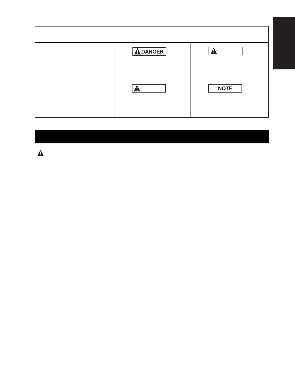
This manual contains information that is important for you to
know and understand. This
information relates to protecting YOUR SAFETY and
PREVENTING EQUIPMENT
PROBLEMS. To help you rec-
ognize this information, we use
the symbols to the right.
Please read the manual and
pay attention to these sections.
URGENT SAFETY INFORMATION - A
HAZARD THAT WILL CAUSE SERIOUS INJURY OR LOSS OF LIFE
IMPORTANT SAFETY INFORMATION- A HAZARD THAT MIGHT
CAUSE SERIOUS INJURY OR LOSS
OF LIFE
INFORMATION FOR PREVENTING
DAMAGE TO EQUIPMENT
INFORMATION THAT YOU SHOULD
PAY SPECIAL ATTENTION TO
GENERAL SAFETY INSTRUCTIONS FOR POWER TOOLS
Failure to heed all safety and operating instructions and warnings regarding use of this
product can result in serious bodily injury.
WARNING
1. Know your power tool
Read the owner’s manual carefully. Learn its
application and limitations as well as the specific potential
hazards peculiar to this tool.
2. Ground all tools (unless double insulated)
If tool is equipped with an approved three-conductor cord
and a three-prong grounding type plug, it should be
plugged into a three hole electrical receptacle. If adapter is
used to accommodate a two-hole receptacle, the adapter
wire must be attached
to a known ground (usually the screw securing
receptacle cover plate). Never remove third prong.
Never connect green ground wire to a terminal.
3. Keep guards in place
Maintain in working order, and in proper adjustment and
alignment.
4. Remove adjusting keys and wrenches
Form a habit of checking to see that keys and adjusting
wrenches are removed from tool before turning it
ON.
5. Keep work area clean
Cluttered areas and benches invite accidents.
Floor must not be slippery due to wax or sawdust.
6. Avoid dangerous environment
Do not use power tools in damp or wet locations
or expose them to rain. Keep work area well lighted.
Provide adequate surrounding work space.
7. Keep children away
All visitors should be kept a safe distance from work
area.
8. Make workshop child-proof
Use padlocks, master switches, or remove starter keys.
9. Do not force tools
Do not force tool or attachment to do a job it was
not designed to perform.
10. Use the right tool
They will do the job better and safer at the rate
for which they were designed.
11. Wear correct apparel
Do not wear loose clothing, gloves, neckties or
jewelry (rings, wristwatches) that may get caught
in moving parts. Non-slip footwear is recommended. Wear
protective hair covering to contain long hair. Roll long
sleeves above the elbow.
12. Use safety goggles (Head Protection)
Wear safety goggles (must comply with ANSI Standard
Z87.1) at all times. Also, use face or
dust mask, if cutting operation is dusty, and ear
protectors (plugs or muffs) during extended periods of
operation.
13. Secure work
Use clamps or a vise to hold work when practical. It’s safer
than using your hands, and both hands
are free to operate tool.
14. Do not overreach
Keep proper footing and balance at all times.
15. Maintain tools with care
Keep tools sharp and clean for best and safest
performance. Follow instructions for lubricating
and changing accessories.
WARNING
CAUTION
SAFETY GUIDELINES – DEFINITIONS
Page 4

1. Always wear eye protection that complies with
ANSI Standard Z87.1.
2. Noise levels vary widely. To avoid possible hearing
damage, wear ear plugs or muffs when using the
Dovetail Jig for hours at a time.
3. For dusty operations, wear a dust mask along
with safety goggles.
4. Do not use this Dovetail Jig with router bits or
guide bushings other than those specified for the
cuts being made.
5. Follow the instructions in your Router Owner’s
Manual.
6.Vibrations caused by the router during use can
cause fasteners to become loose. Before use and
periodically during use, check all fasteners to make
sure that they are all are tight and secure.
7. Do not use this product until all assembly installation steps have been completed, and you have read
and understand all safety and operational instructions in this manual, and the Router Owners Manual.
8. Make sure that the router bit is properly positioned
in the router so that it does not contact the guide
bushing or the template when cutting.
9. The Dovetail Jig must be securely mounted to a
workbench or other stable surface when in use. The
front of the base should overhang the front of the
workbench by no more than 1/4" to provide clearance when clamping workpieces to the Dovetail Jig.
10. Do not use the Dovetail Jig as a work surface.
Doing so may cause damage to the Dovetail Jig,
which can cause it to be unsafe to use. A workbench
should be used for this purpose.
11. This product is designed to cut flat workpieces.
Do not cut or attempt to cut workpieces that are
not flat or that are irregularly shaped.
12. This product is to be used for cutting wood workpieces only. Do not use this product to cut metal
or any other non-wood material.
13. This product has been designed to cut workpieces having thicknesses of 3/8" to 1". Do not use
for workpieces of any other thicknesses.
14. Do not clamp any workpieces to the Dovetail Jig
or make any adjustments to the Dovetail Jig unless
the router has been turned off, the router bit is not
turning, and the Router has been disconnected from
the electrical outlet.
15. When setting “the-depth-of-cut” of the router
bit, make sure that the workpiece is clamped to the
Dovetail Jig in such a manner that the router bit
does not cut into the Dovetail base causing damage to it or possible serious injury to you.
4
16. Disconnect tools before servicing
Before servicing, when changing accessories
such as blades, bits, cutters, etc.
17. Avoid accidental starting
Make sure switch is in OFF position before plugging in.
18. Use recommended accessories
Consult the owner’s manual for recommended accessories
and follow the instructions. The use
of improper accessories may cause hazards.
19. Never stand on tool
Serious injury could occur if the tool is tipped or if the cutting tool is accidentally contacted.
DO NOT store materi-
als above or near the tool making it
necessary to stand on the tool to reach them.
20. Check damaged parts
Before further use of the tool, any guard or other
part that is damaged should be carefully checked to
ensure that it will operate properly and perform its
intended function. Check for alignment of moving
parts, binding of moving parts, breakage of parts,
mounting, and any other conditions that may affect
its operation. A guard or any other part that is
damaged should be properly repaired or replaced.
21. Direction of feed
Feed work into a blade or cutter AGAINST the
direction of rotation of the blade or cutter only.
22. Never leave tool running unattended
Turn power OFF. DO NOT leave tool until it comes
to a complete stop.
23. Keep hands away from cutting area
24. Store idle tools
When not in use, tools should be stored in dry,
high or locked-up place – out of reach of children.
25. Do not abuse cord
Keep cord away from heat, oil and sharp edges.
26. Outdoor extension cords
When tool is used outdoors, use only extension
cords suitable for use outdoors and so marked.
27. Never use in an explosive atmosphere
Normal sparking of the motor could ignite fumes,
flammable liquids, or combustible items.
28. Drugs, alcohol, medication
DO NOT operate tool while under the influence
of drugs, alcohol, or any medication.
Read and Understand this instruction book
completely BEFORE using this product.
.
ADDITIONAL SAFETY INSTRUCTIONS FOR THE
INDUSTRIAL DOVETAIL JIG
Page 5

5
16. ALWAYS UNPLUG THE
ROUTER FROM THE ELECTRICAL OUTLET
BEFORE INSTALLING OR REMOVING ROUTER
BITS FROM THE ROUTER AND WHEN ADJUSTING THE CUTTING DEPTH OF THE ROUTER BIT;
OR WHEN INSTALLING OR CHANGING GUIDE
BUSHINGS.
17. NEVER LIFT THE ROUTER UPWARDS WHEN
THE ROUTER IS “ON”, THE ROUTER BIT IS
ROTATING, AND THE GUIDE BUSHING IS NEAR
OR TOUCHING THE TEMPLATE, BECAUSE THIS
WILL CAUSE THE ROUTER BIT TO CUT INTO
THE TEMPLATE AND DAMAGE IT.
WARNING
INTRODUCTION
• Your Vermont American Industrial Dovetail Jig is an
accessory that is used with Routers allowing you to
make drawers, chests, and similar items requiring
dovetail joints. The joints are used to make the front,
back, and sides of the workpiece.
• Your Industrial Dovetail Jig comes with two templates and two guide bushings for making half-blind
and through or open joints.
• Your Industrial Dovetail Jig also comes with a
universal router adapter plate that will permit the
Industrial Dovetail Jig to be used with most popular
routers.
• The Dovetail Jig will allow you to make 1" spaced
flush, flush-offset, and 3/8" rabbeted half-blind
dovetail joints.
• The Dovetail Jig will also allow you to make 1"
spaced open, or through, dovetail joints.
• Workpieces up to 16" wide can be accommodated.
• Workpieces with thicknesses between 3/8" and 1"
can be accommodated.
• The Dovetail Jig Base has six pockets molded into
its front which are gauges to aid you setting the
“depth-of- cut” for commonly used depths: 3/8", 1/2",
5/8", 3/4", 7/8", and 1".
• Vermont American router bits, #22501 and #22437,
or Magna router bits, #M91113 and #M91016,
WHICH MUST BE PURCHASED SEPARATELY, are
required for making the THROUGH or OPEN joints.
• Vermont American router bit, #22500, or
Magna router bit, #M91114, WHICH MUST BE
PURCHASED SEPARATELY, is required for making
the HALF-BLIND joints.
• Your Vermont American Industrial Dovetail Jig
comes with two templates and two guide bushings.
Each of the templates has a label, describing the
joint that can be cut with it, along with set-up
information, the router bit and the guide bushing
required, and the the stop block setting for a
particular joint.
UNPACKING AND CHECKING CONTENTS
• If any parts are missing or cannot
be accounted for, do not attempt to assemble, install,
or use the Industrial Dovetail Jig until the missing
parts have been obtained and the product has been
assembled correctly.
• Contact customer service at 1-800-742-3869, ext. 8359
for missing or replacement parts.
WARNING
Refer to Parts List on Page 47.
• In order to simplify handling and to minimize any
damage that may occur during shipping, your
Industrial Dovetail Jig is packaged assembled.
• Separate all loose parts from the packing materials
and check each one with the illustrations and list of
parts at the end of this manual to make sure that
all loose parts are present before discarding any
packaging material.
Page 6
6
ASSEMBLY INSTRUCTIONS
IMPORTANT
ALTHOUGH YOUR INDUSTRIAL DOVETAIL JIG
COMES ASSEMBLED, THE FOLLOWING ASSEM-
BLY INSTRUCTIONS ARE BEING INCLUDED FOR
REFERENCE PURPOSES SHOULD IT BECOME
NECESSARY FOR YOU TO DISASSEMBLE AND
REASSEMBLE THE DOVETAIL JIG.
PROCEED TO THE SECTION ALIGNMENT OF
THE TEMPLATES AND THEN CONTINUE WITH
THE SECTIONS FOLLOWING ALIGNMENT OF
THE TEMPLATES.
THE TEMPLATES MUST BE ALIGNED BEFORE
ANY ROUTING IS TO TAKE PLACE.
ASSEMBLY OF THE RIGHT SIDE TEMPLATE SUPPORT TO THE DOVETAIL BASE
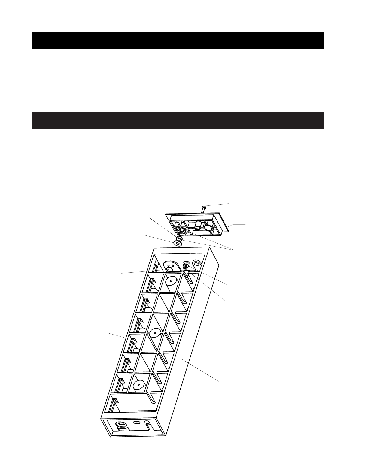
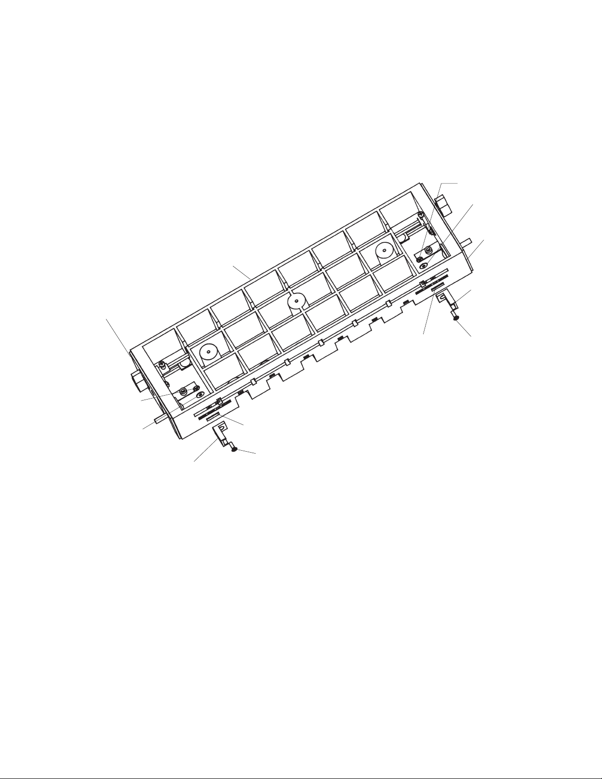
1. Place the dovetail base topside down on a flat surface.
2. Insert one of the 5/16-18 x 2" long round head square
TOOLS REQUIRED
• A medium sized Phillips screwdriver
• A small or medium adjustable wrench
neck bolts into the slot in the right side of the base.
(NOTE: The right side of the base is identified by the
words RIGHT SIDE molded into it.)
3. Place a 11/32" I.D. x 7/8" O.D. washer onto the bolt as
shown in Figure 1.
4. Thread a 5/16-18 hex nut onto the bolt, as shown, until
it bottoms out against the washer.
5. Back off the nut from the washer between 1/4 and 1/2
5/16-18 HEX NUT
11/32" I.D. X 7/8" O.D. WASHER
5/16-18 X 2" LONG ROUND HEAD
SQUARE NECK BOLT
DOVETAIL BASE
10-32 X 5/8" LONG PANHEAD
MACHINE SCREW
RIGHT TEMPLATE SUPPORT
HEXES MUST LINE UP
# 10-32 HEX NUT
BACK OF DOVETAIL BASE
13/64" I.D. X 9/16" O.D. WASHER
FIGURE 1
Page 7
7
ASSEMBLY
turns. Align the nut so that the corners of the nut are vertically lined up as shown. Note the alignment of the hex
pocket in the template support. The bolt should be free to
move side to side; if it does not, loosen the nut 1/3 turn or
until the corners of the nut point up and down.
6. Assemble the right template support to the right side of
the dovetail base so that the hex nut lines up and fits into
the hex pocket in the right template support. (NOTE: The
right template support has the words RIGHT SIDE molded
into it for identification.)
7. Assemble a #10-32 x 5/8" long panhead machine screw,
a 13/64" I.D. x 9/16" O.D. washer, and a #10-32 hex nut to
the base as shown to hold the template support in place.
Securely tighten the nut and screw.
8. The template support should move freely front to back
along the side of the base. If it does not, it means that the
5/16-18 hex nut is too tight on the bolt and should be loosened. To do this, remove the fasteners assembled in step
7, and remove the template support; repeat steps 4
through 7.
ASSEMBLE THE LEFT SIDE TEMPLATE SUPPORT TO
THE DOVETAIL BASE THE SAME AS THE RIGHT SIDE
TEMPLATE SUPPORT WAS ASSEMBLED.
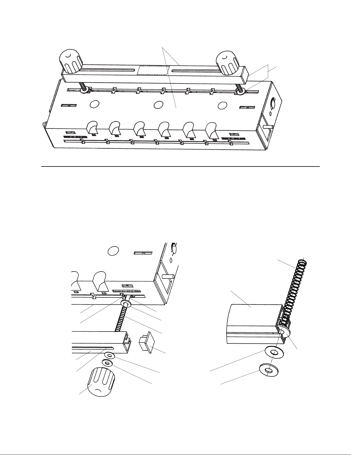
ASSEMBLY OF THE TOP CLAMPING BAR TO THE DOVETAIL BASE
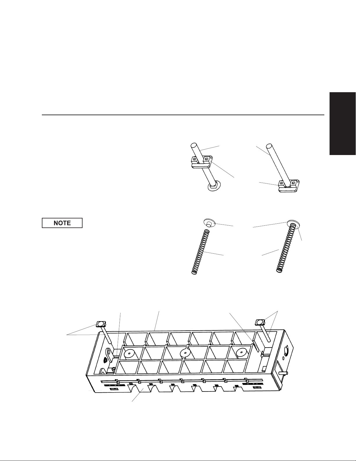
1. Assemble one of the bolt supports to both of the
5/16-18 X 3-1/2" long round head square neck bolts as
shown in Figure 2.
2. Align the square on the bolt with the square hole in the
bolt support. The bolt support is to "bottom-out" against the
bolt as shown in Figure 3.
3. Assemble one of the springs to each of the nylon spring
retainers by pushing the spring over the raised cylindrical
portion of the spring retainer as shown in Figure 3A and
Figure 3B.
4. Position the dovetail base on a flat smooth surface so
the back of the base rests on the surface.
ALTHOUGH BOTH ENDS OF THE
DOVETAIL BASE ARE SHOWN ASSEMBLED IN THE
FOLLOWING FIGURES, THE ACTUAL ASSEMBLY IS
DONE ONE END AT A TIME.
5. From the bottom of the base, insert a bolt with bolt support through the slot in the top of the base so the raised
portion of the bolt support goes into the slot, as shown in
Figure 4.
5/16-18 X 3-1/2"
LONG ROUND
HEAD SQUARE
NECK BOLT
BOLT
SUPPORT
NYLON
SPRING
RETAINER
COMPRESSION
SPRING
SPRING TO
BOTTOM
OUT
AGAINST
SURFACE
FIGURE 4
FIGURE 2 FIGURE 3
FIGURE 3A FIGURE 3B
SLOT IN
DOVETAIL BASE
DOVETAIL BASE
BOLT
AND
BOLT
SUPPORT
FRONT OF DOVETAIL BASE
BOLT AND BOLT
SUPPORT
SLOT IN
DOVETAIL
BASE
Page 8

8
6. Place an 11/32" I.D. X 7/8" O.D. washer and then a
5/16" I.D. X 7/8" O.D. thick nylon washer over the bolt. It
will be necessary to hold the bolt in place when performing
this and the following steps.
HELPFUL HINTS: Position the bolt and the bolt support
under the notch in the rib as shown in Figure 5, to help
hold the bolt in place.
7. Place a spring over the bolt, as shown in Figure 6.
8. Place a 5/16" I.D. X 7/8" O.D. thick nylon washer and
then an 11/32" I.D. X 7/8" O.D. washer over the bolt and
press down on the spring until just the end of the bolt
sticks out past the end of the washer.
9. Slide the clamping bar over the bolt so that the washers
are sandwiched between the spring and the inside of the
clamping bar as shown in Figure 6. NOTE: THE SPRING
MUST PUSH AGAINST THE THICK NYLON WASHERS
AND NOT AGAINST THE STEEL WASHERS.
10. Place an 11/32" I.D. X 7/8" O.D. thin nylon washer and
an 11/32" I.D. X 7/8" O.D. washer over the bolt. It will be
necessary for you to press down on the clamping bar while
doing this.
11. Take one of the clamping knobs and thread it onto the
bolt as shown. DO NOT THREAD the knob completely
onto the bolt––just enough so the knob holds the clamping
bar in place.
12. Repeat above steps 4 through 10 for the other end of
the clamping bar.
13. Assemble the end caps to the ends of the clamping bar
by pressing them in; they are designed to be “force-fit” into
NOTCH
IN RIB
SLOT IN
DOVETAIL
BASE
BOLT AND
BOLT
SUPPORT
FIGURE 5
FIGURE 6 Assemble clamping bar, knobs, end caps on both ends as shown
CLAMPING BAR DETAIL
the bar in one way only. It may be necessary to “tap” them
in by gently hitting them with a rubber mallet or a piece of
wood––since they fit very tightly into the clamping bar.
USE CARE WHEN DOING THIS SO AS NOT TO DAMAGE THE END CAPS.
USE CARE THAT THE CAPS ARE PROPERLY ALIGNED
AS SHOWN WHEN ASSEMBLING THEM TO THE BAR.
14. Tighten the clamping knobs onto the bolts so that the
space between the bottom of the clamping bar should be
parallel to the top of the base.
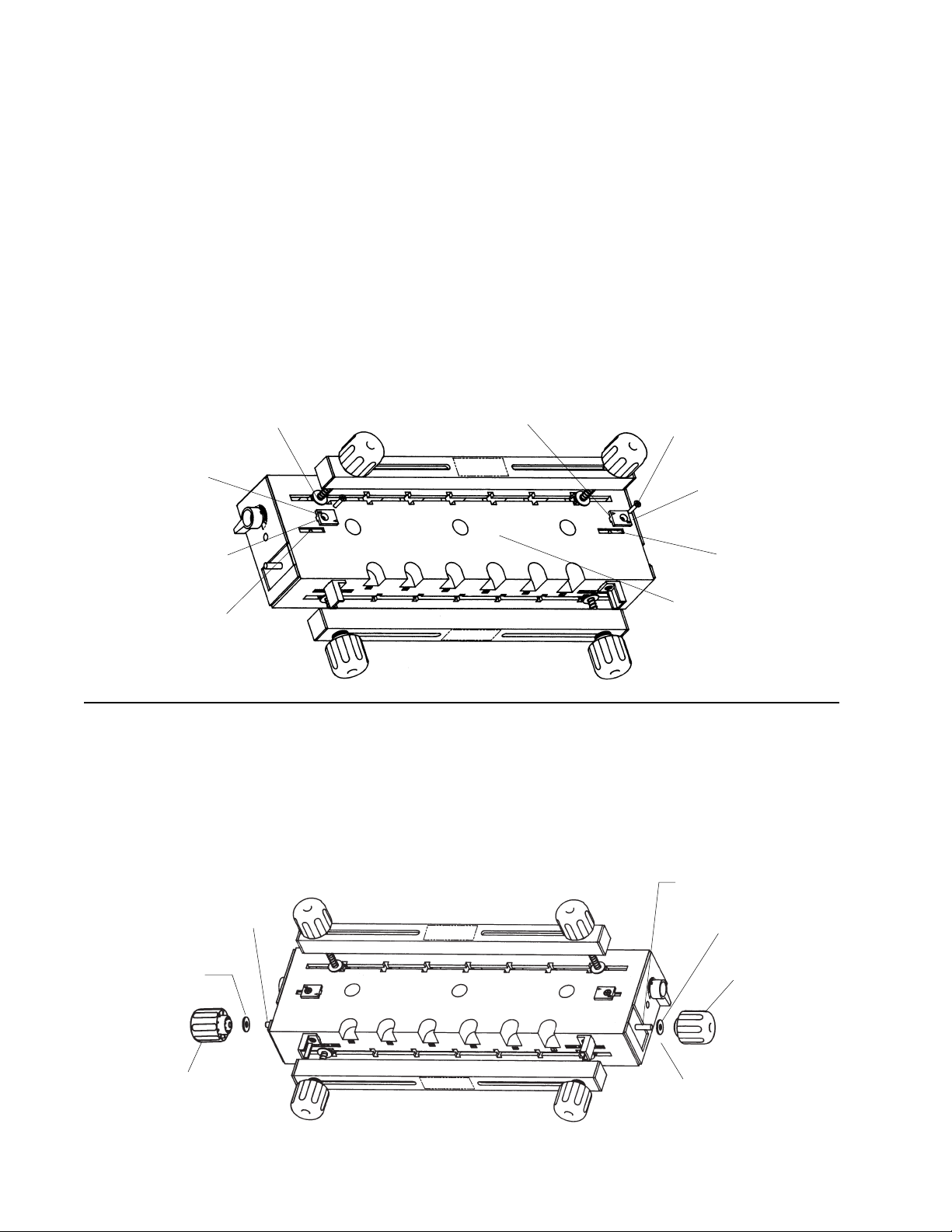
15. After completing the above steps your Dovetail Jig
should look like the illustration in Figure 7.
CLAMPING KNOB
SPRING AND
NYLON SPRING
RETAINER FIT
INSIDE THE
OPEN SIDE OF
THE CLAMPING
BAR
(SEE CLAMPING
BAR DETAIL)
11/32" I.D.
X 7/8" O.D. WASHER
11/32" I.D. X 7/8" O.D.
THIN NYLON WASHER
CLAMPING BAR
CLAMPING BAR
END CAP
OPEN SIDE OF
THE CLAMPING BAR
POINTS TOWARD
THE TOP SURFACE
OF THE DOVETAIL
BASE
11/32" I.D.
X 7/8" O.D.
THICK
NYLON
WASHER
TOP SURFACE OF
THE DOVETAIL
RIGHT
TEMPLATE
SUPPORT
BOLT
SUPPORT
3 1/2" BOLT
COMPRESSION
SPRING
NYLON SPRING
RETAINER
(RETAINER ABUTS THE
CLAMPING BAR)
11/32" I.D. X 7/8"
O.D. WASHER
11/32" I.D. X 7/8" O.D.
THICK NYLON
WASHER
CLAMPING BAR (SHOWN WITH
END CUT AWAY AND SECTIONED
SO NYLON SPRING RETAINER
PLACEMENT CAN BE SEEN)
COMPRESSION
SPRING
Page 9
9
CLAMPING BAR PARALLEL TO
TOP OF BASE
SPACING TO BE
APPROXIMATELY
1-1/2"
FIGURE 7
ASSEMBLY OF THE FRONT CLAMPING BAR TO THE DOVETAIL BASE
1. Assemble the front clamping bar to the front of the dovetail base following the same procedure used to assemble
the top clamping bar to the dovetail base as shown in
FIGURE 8
CLAMPING BAR
(SHOWN WITH END
CUT AWAY AND
SECTIONED SO
NYLON SPRING
RETAINER PLACEMENT CAN BE
SEEN)
COMPRESSION
SPRING
NYLON
SPRING
RETAINER
(RETAINER
ABUTS THE
CLAMPING
BAR)
4 1/2" BOLT
11/32" I.D. X 7/8" O.D.
THICK NYLON WASHER
COMPRESSION SPRING
CLAMPING BAR
END CAP
11/32" I.D. X 7/8" O.D.
THIN NYLON WASHER
11/32" I.D. X 7/8" O.D.
CLAMPING KNOB
NYLON SPRING
RETAINER
BOLT SUPPORT
DOVETAIL BASE
CLAMPING BAR
Figure 8. The 5/16-18 X 4-1/2" long round head square
neck bolts are used.
Page 10
10
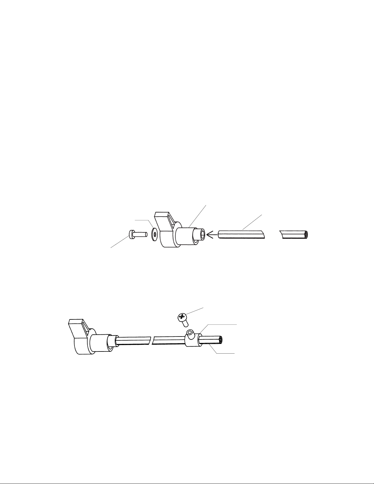
ASSEMBLY OF THE CAM HANDLES AND PIVOT SHAFT TO THE DOVETAIL BASE
• After the cam handles and pivot shaft have been assembled to the base, it will be possible to accurately position
the templates for close fitting joints.
• Note that there are some graduations on both template
supports.
• Rotating the cam handle so that the pointer lines up with
one of the graduations permits accurate front-to-back positioning of the template.
• Cam handles are designed to provide infinite template
adjustment.
• One graduation equals 1/64" of movement of the template.
• Rotating the cam handle so that the lever moves toward
the front of the base, causes the template to also move
towards the front of the base.
•Conversely rotating the cam handle so that the lever
moves toward the back of the base, causes the template
to also move towards the back of the base also.
13/64" I.D. X 9/16" O.D. WASHER
#10-32 X 5/8" LONG
PANHEAD MACHINE SCREW
CAM HANDLE
PIVOT SHAFT
#10-16 X 1/2" LONG PANHEAD TAPPING SCREW
RETAINER
PIVOT SHAFT
FIGURE 9
FIGURE 10
1. Assemble one of the cam handles to the pivot shaft
using a #10-32 x 5/8" long panhead machine screw and a
13/64" I.D. x 9/16" I.D. washer. as shown in Figure 9.
2. Use care so that the pivot shaft fits into the hex-shaped
hole in the cam handle. The pivot shaft may fit tightly into
the cam handle; this is normal.
3. Make sure that the pivot shaft bottoms-out inside the
cam handle.
4. Securely tighten the screw.
NOTE: THE NEXT TWO STEPS ARE PRE-ASSEMBLY
STEPS.
5. Slide the retainer over the end of the pivot shaft for
about 2". The retainer may fit tightly; this is normal.
6. Thread the #10-16 x 1/2" long panhead tapping screw
into the hole in the retainer until it bottoms-out against the
pivot shaft. (The screw will fit tightly in the hole.) See
Figure 10.
Page 11
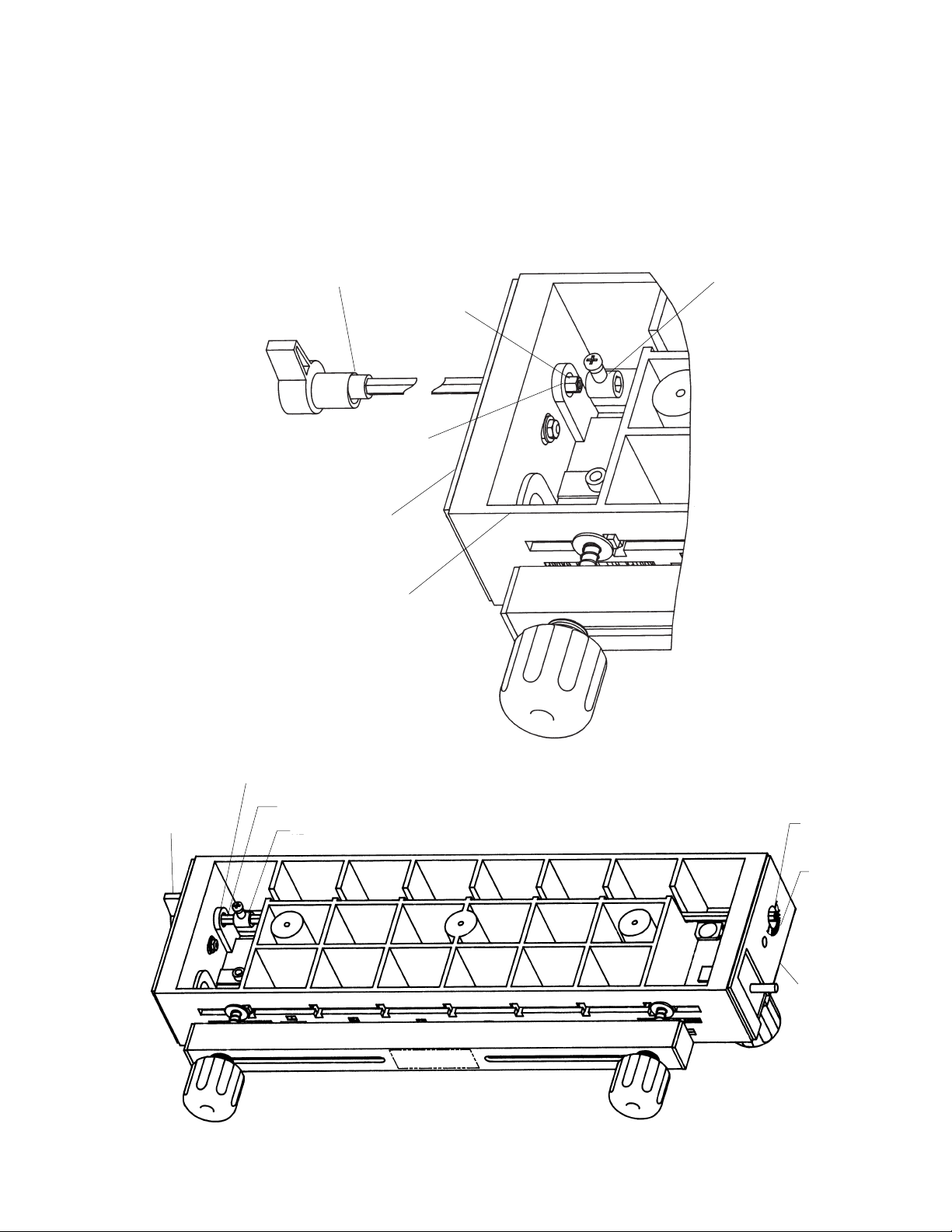
11
7. Loosen the screw about one turn. Remove the retainer
from the shaft and set it aside temporarily.
8. Assemble the pivot shaft with cam handle to the base by
inserting the end of the pivot shaft through the holes in the
right template support and the base.
9 . MAKE SURE THE ORIENTATION OF THE CAM HANDLE IS AS SHOWN IN FIGURE 11.
10. Place the retainer at the location shown in Figure 12
and push the pivot shaft through. THE ORIENTATION OF
THE RETAINER RELATIVE TO THE CAM HANDLE WITH
SCREW MUST BE AS SHOWN.
NOTE: THE RETAINER MAY FIT TIGHTLY ON THE
PIVOT SHAFT; THIS IS NORMAL.
11. Continue pushing the pivot shaft through the holes and
the retainer until the end of the pivot shaft extends out of
the left template support as show in Figure 12.
12. Make sure the end of the cam handle fits into the hole
in the base as shown.
CAM HANDLE
PIVOT SHAFT
RETAINER
HOLE IN BASE
RIGHT TEMPLATE
DOVETAIL BASE
FIGURE 11
FIGURE 12
PIVOT SHAFT
RETAINER
PIVOT
HOLE IN
BASE
LEFT
TEMPLATE
SUPPORT
CAM
HANDLE
HOLE IN BASE
Page 12
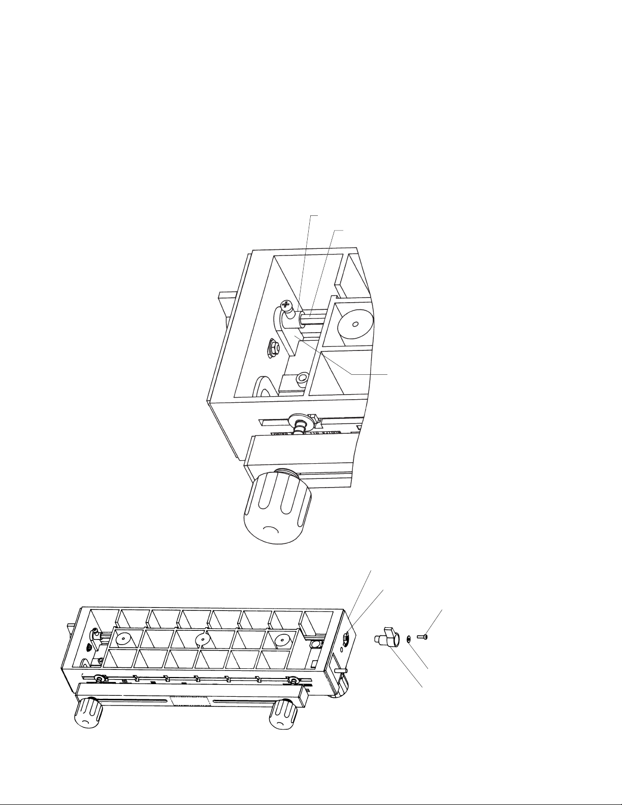
12
13. With the cam handle pushed in against the base,
position the retainer against the side wall of the base, as
shown in Figure 13. The retainer should barely touch the
side wall of the base. The purpose of the retainer is to
prevent or minimize the side-to-side of the cam handle and
pivot shaft.
14. Assemble the other cam handle to the other end of the
pivot shaft using a 13/64" I.D. x 9/16" O.D. washer and
a#10-32 X 5/8" long panhead machine screw, as shown in
Figure 14.
15. Make sure that the cam handle lines up with the cam
handle at the other end of the pivot shaft and that the end
RETAINER
SIDE WALL OF BASE
of the cam handle fits into the hole in the base.
16. Tighten the screw securely.
17. Rotate one of the cam handles–It should rotate freely
and move the template supports
18. If this does not happen, loosen the screw on the retainer and move the retainer away from the side wall slightly.
19. Securely retighten the screw.
20. If there is too much side-to-side movement (play) of
the cam handles; loosen the screw in the retainer and
move the retainer closer to the side wall of the base.
21. Securely retighten the screw.
LEFT TEMPLATE SUPPORT
PIVOT SHAFT
#10-32 X 5/8" LONG
PANHEAD MACHINE
SCREW
13/64" I.D. X 9/16" O.D. WASHER
CAM HANDLE
FIGURE 13
FIGURE 14
Page 13
13
ASSEMBLY OF THE FRONT STOP BLOCKS TO THE DOVETAIL BASE
1. Assemble the front stop blocks to the front of the dovetail base, at each end, using #10-32 x 5/8" long flathead
machine screws, 13/64" I.D. x 9/16" O.D. washers, and
#10-32 hex nuts, as shown in Figure 15.
2. Make sure that the open rib portion fits into the slot in
the front of the base. The stop block will fit into the slot in
one position only.
3. Tighten the screw securely onto the nut.
4. Assemble the other front stop block to opposite end of
the dovetail base in the same manner.
DOVETAIL BASE
RIGHT
TEMPLATE
SUPPORT
#10-32 HEX NUT
13/64" I.D. X 9/16"
O.D. WASHER
FRONT STOP BLOCK
SLOT
#10-32 X 5/8" LONG FLATHEAD
MACHINE SCREW
FRONT OF DOVETAIL BASE
SLOT
#10-32 HEX NUT
13/64" I.D. X 9/16" O.D.
WASHER
LEFT TEMPLATE
SUPPORT
FRONT STOP BLOCK
#10-32 X 5/8" LONG
FLATHEAD MACHINE
SCREW
FIGURE 15
FOR REASONS OF CLARITY, THE FRONT
CLAMPING BAR, KNOBS, BOLTS AND
SPRINGS ARE NOT SHOWN
Page 14
14
ASSEMBLY OF THE TOP STOP BLOCKS TO THE DOVETAIL BASE
• The top stop blocks are assembled to the top of the
dovetail base in one of two ways depending upon which
style of dovetail joint is to be cut:
a. HALF-BLIND FLUSH JOINTS—The “A” on the stop
block faces toward the “middle of the base”.
b. HALF-BLIND RABBET JOINTS—The “B” on the
stop block faces toward the “middle of the base”.
c. THROUGH JOINTS—The “A” on the stop block
faces toward the “middle of the base”.
• Since the flush joint is the more commonly used joint, the
following instructions apply to the assembly of the stop
blocks for this style joint.
1. Position the dovetail Jig right side up on a flat surface
2. Assemble one of the top stop blocks to the top surface
of the base using a #10-32 x 7/8" long flathead machine
ASSEMBLY OF THE CLAMPING KNOBS TO THE DOVETAIL BASE
1. Assemble 11/32" I.D. x 7/8" O.D. washers onto the 5/1618 bolts at both ends of the dovetail base as shown in
Figure 17.
2. Assemble the clamping knobs onto the bolts as shown.
screw, as shown in Figure 16. The screw threads into the
hole in the bottom of the slot.
3. Make sure that the “A” faces the “middle of the base”.
4. Make sure the open rib portion of the stop block fits into
the slot in the top surface of the base.
5. Assemble the remaining top stop block to the opposite
end of the base in the same manner
6.Again make sure that the “A” faces the “middle of the
base”.
7. Tighten both screws securely.
8. To reposition the stop blocks for rabbet joints, simply
loosen the screws just enough so that the ribs on the stop
blocks come out of the slot. The stop block is then rotated
180° to the alternate position, so the “B” faces the middle
of the base, and securely retighten the screws.
5/16-18 X 2" LONG ROUND
HEAD SQUARE NECK BOLT
5/16-18 X 2" LONG ROUND
HEAD SQUARE NECK BOLT
11/32" I.D. X 7/8"
O.D. WASHER
CLAMPING
KNOB
CLAMPING
KNOB
11/32" I.D. X 7/8"
O.D. WASHER
1/2" SPACING BETWEEN
WASHER AND TEMPLATE
SUPPORT (BOTH ENDS)
FIGURE 16
FIGURE 17
#10-32 X 7/8" LONG FLAT HEAD
MACHINE SCREW
#10-32 X 7/8" LONG FLAT
HEAD MACHINE SCREW
RIB ON STOP BLOCK
TOP STOP BLOCK
RIB ON STOP BLOCK
SLOT IN TOP
OF BASE
TOP STOP BLOCK
MIDDLE OF THE BASE
SLOT IN TOP
OF BASE
3. Thread the clamping knobs onto the bolts so that the
spacing between the washer and the template supports is
approximately 1/2".
4. Set the dovetail base aside for the time being and continue on with the next section.
Page 15
15
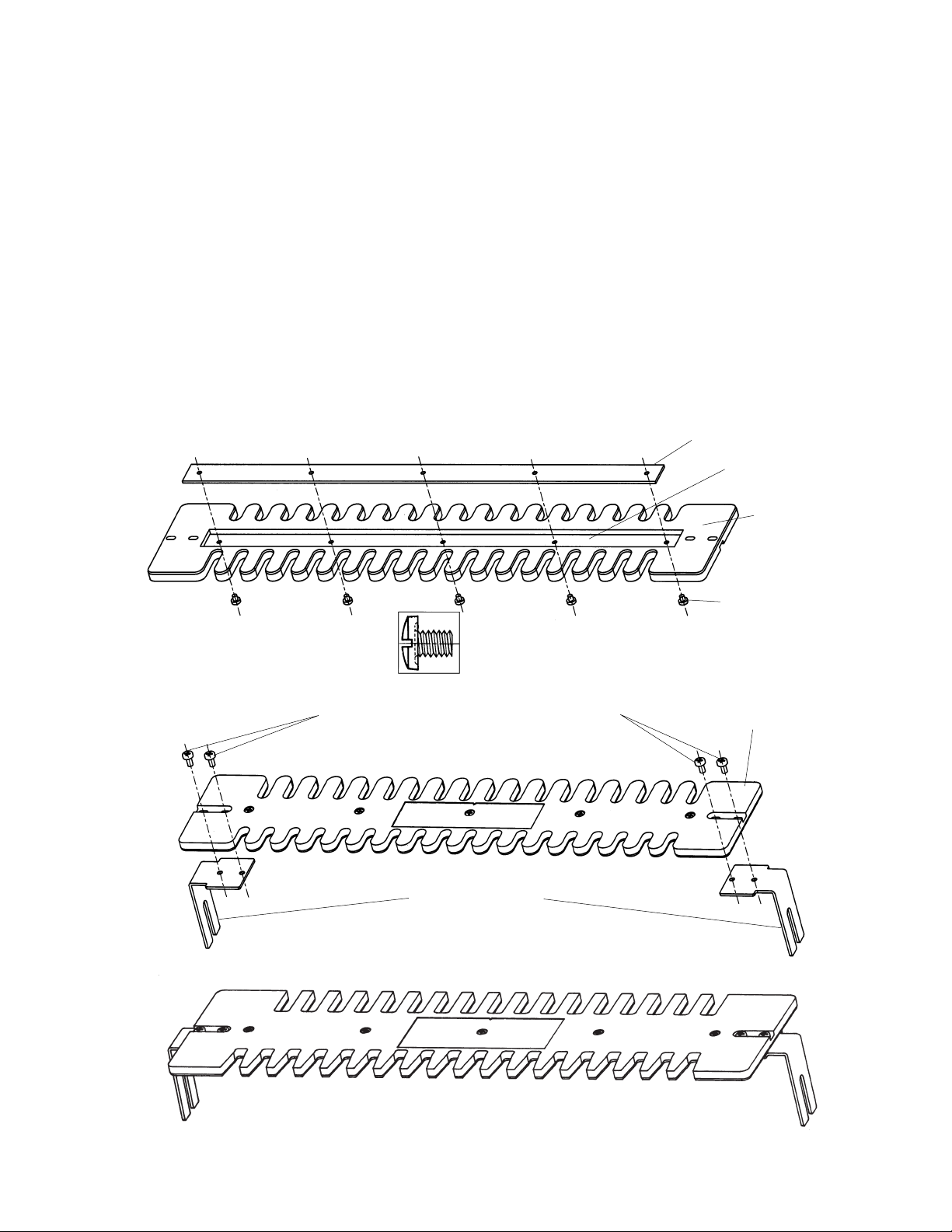
FIGURE 20
FIGURE 19
FIGURE 18
#10-32 X 3/16" LONG PANHEAD MACHINE
TEMPLATE
TEMPLATE BRACKET
TEMPLATE STIFFENER
RECTANGULAR SLOT
TEMPLATE
#8-36 X 3/16" LONG
PANHEAD MACHINE
SCREW
SLOTTED BINDING HEAD
MACHINE SCREW
ASSEMBLY OF THE TEMPLATES
• Place the template stiffener into the rectangular slot in the
underneath side of the template, as shown in Figure 18.
NOTE: THE TEMPLATE FOR CUTTING HALF-BLIND
JOINTS IS BEING USED AS AN ILLUSTRATION IN THE
FOLLOWING FIGURES.
1. Thread a #8-36 x 3/16" long panhead machine screw
through each of the five holes in the template and into the
threaded holes in the template support, as shown in
Figure 18 and securely tighten all of the screws.
NOTE: ON SOME EARLY VERSIONS OF THIS PRODUCT, A SLOTTED BINDING HEAD MACHINE SCREW
HAS BEEN SUBSTITUTED FOR THE PANHEAD SCREW
SPECIFIED FOR ASSEMBLING THE TEMPLATE SUPPORTS TO THE TEMPLATES. (SEE THE SCREW ILLUSTRATION IN FIGURE 18.)
2. Assemble the template brackets to the template using
four #10-32 x 3/8" long panhead machine screws, as
shown in Figure 19.
3. MAKE SURE THAT THE TEMPLATE BRACKETS ARE
ASSEMBLED TO THE UNDERNEATH SIDE OF THE
TEMPLATE, AS SHOWN IN FIGURE 19, AND THAT THE
ALIGNMENT OF THE BRACKETS IS ALSO AS SHOWN
IN THE FIGURE.
4. IT IS NOT NECESSARY FOR THE SCREWS TO BE
TIGHTENED AT THIS STAGE; THE TEMPLATE BRACKETS SHOULD BE FREE TO MOVE WITH RESPECT TO
THE TEMPLATE OR ELSE IT WILL NOT BE POSSIBLE
TO ALIGN THE TEMPLATE AS DESCRIBED IN THE
NEXT SECTION.
5. The assembled template should look like the illustration
in Figure 20.
6. Assemble the template stiffener and the template brackets to the TEMPLATE FOR CUTTING THROUGH JOINTS
using the same method described in the preceding steps 1
through 5. Refer to Figure 20.
Page 16
16
ALIGNMENT OF THE TEMPLATES
• In order for the Dovetail Jig to function properly, it is
necessary for the templates to be aligned with respect to
dovetail base. The reason for this, is that dovetail cuts are
at both ends of the Dovetail Jig. When properly aligned,
the result being all mating corners will always be lined up.
• NOTE: THE TEMPLATE FOR CUTTING HALF-BLIND
JOINTS IS BEING USED AS AN ILLUSTRATION IN THE
FOLLOWING FIGURES.
1. With the dovetail base still having the 1/2" spacing
between the washer and the template supports (Refer to
Figure 17), assemble the template assembly to the dovetail base so that:
a) the slot in the template bracket fits over the bolt
b) the leg of the template bracket is between the washer
and the template support, and
c) the legs fit into the slots in the template supports, as
shown in Figure 21.
d) NOTE: THIS PROCEDURE MUST BE FOLLOWED
WHENEVER THE TEMPLATE IS INSTALLED ON THE
DOVETAIL JIG. IT IS MOST IMPORTANT THAT LEG
OF THE TEMPLATE BRACKET ALWAYS BE
BETWEEN THE WASHER AND THE TEMPLATE SUPPORT OR ELSE THE TEMPLATE WILL NOT BE
PROPERLY POSITIONED FOR CUTTING ACCURATE
DOVETAILS.
For initial setup, Allow the legs of the template bracket to
“bottom out” in the slots in the template supports as
shown in Figure 21.
• TO REMOVE THE TEMPLATE FROM THE DOVETAIL
JIG, LOOSEN THE CLAMPING KNOBS SO THAT SPACING BETWEEN THE TEMPLATE BRACKET AND THE
WASHER IS ABOUT 1/2"; GENTLY LIFT THE TEMPLATE
UPWARD FROM THE DOVETAIL BASE SO THAT THE
TEMPLATE BRACKET CLEARS THE SLOTS IN THE
TEMPLATE SUPPORT AND STORE IN A CONVENIENT
LOCATION.
2. Lightly tighten the clamping knobs at both ends of the
base so that the template brackets are held in place
against the template supports as shown in Figure 21.
3. Move the template from side to side on the template
brackets so that it is centered with respect to the template
brackets. This means that the template and brackets
should look like one of the following figures: Figure 22,
Figure 23. or Figure 24. Move template front-to-back so
that front edge of template is parallel with the front of the
dovetail base. In each condition the template and the template brackets MUST be symmetrical with each other. The
figures do not show the complete Dovetail Jig, but only the
underneath side of the template with template brackets
correctly positioned, in order that the correct positions of
RIGHT TEMPLATE SUPPORT
WASHER
BOLT
TEMPLATE BRACKET
SLOT IN THE TEMPLATE BRACKET
SLOT IN THE TEMPLATE SUPPORT
TEMPLATE BRACKET “BOTTOMS-OUT” AGAINST
THIS SURFACE (BOTH ENDS OF DOVETAIL BASE)
FIGURE 21
Page 17

17
CONDITION ONE: TEMPLATE BRACKETS PROTRUDE BEYOND TEMPLATES
TEMPLATE
DISTANCE BETWEN THESE
SURFACES MUST BE EQUAL
AT BOTH ENDS
TEMPLATE BRACKET
CONDITION TWO: TEMPLATE PROTRUDES BEYOND TEMPLATES BRACKETS
TEMPLATE
DISTANCE BETWEN THESE
SURFACES MUST BE EQUAL
AT BOTH ENDS
TEMPLATE BRACKET
CONDITION THREE: TEMPLATE EVEN WITH TEMPLATE BRACKETS
TEMPLATE
DISTANCE BETWEN THESE
SURFACES MUST BE EQUAL
AT BOTH ENDS
TEMPLATE BRACKET
FIGURE 22
FIGURE 23
FIGURE 24
Page 18

18
4. After the template brackets have been correctly positioned on the template securely tighten the four screws
holding the template brackets to the template.
5. Remove the template assembly from the base and set it
aside for now.
6. Align the other template assembly in the same manner.
IT SHOULD BE NOTED THAT YOU MAY FIND, THAT
AFTER MAKING SOME SAMPLE CUTS, SLIGHT
ADJUSTMENTS MAY BE REQUIRED. HOW TO MAKE
THESE ADJUSTMENTS IS EXPLAINED IN TWO OF THE
FOLLOWING SECTIONS: “TROUBLESHOOTING FOR
HALF BLIND JOINTS” or “TROUBLESHOOTING FOR
OPEN (THROUGH) JOINTS”.
7. Remove the template assembly from the base and
set it aside for now. (Figure 25 below, is an example of
INCORRECTLY positioned template brackets.)
FIGURE 25
TEMPLATE BRACKET
THE TEMPLATE EXTENDS
BEYOND THE TEMPLATE
BRACKET
CONDITION FOUR: THIS CONDITION IS NOT CORRECT –
TEMPLATE BRACKET EXTENDS BEYOND THE TEMPLATE AND
THE TEMPLATE EXTENDS BEYOND THE TEMPLATE BRACKET.
• SIMPLY MAKE SURE BRACKETS ARE POSITIONED THE SAME AT EACH END
TEMPLATE
TEMPLATE BRACKET
THE TEMPLATE
BRACKET EXTENDS
BEYOND THE
TEMPLATE
ASSEMBLY OF THE ADAPTER PLATE TO THE ROUTER
ALWAYS MAKE SURE THAT THE ROUTER IS "TURNED
OFF" AND THAT THE ELECTRICAL CORD HAS BEEN
UNPLUGGED FROM THE ELECTRICAL OUTLET
BEFORE ASSEMBLING THE ADAPTER PLATE AND A
GUIDE BUSHING TO THE ROUTER; OR WHEN MAKING
ANY ADJUSTMENTS, OR CHANGING ROUTER BITS IN
THE ROUTER.
1. Remove any router bit currently installed in the router.
WARNING
2. Remove the router base plate now on the router, by
removing the screws holding the base plate to the router.
3. Depending on the make of router, either three or four of
the following screw types and sizes will have been used:
a) #8 (.164 dia) Pan Head Screw
b) #10 (.190 dia) Pan Head Screw
c) #8 (.164 dia) Flat Countersunk Head Screw
d) #10 (.190 dia) Flat Countersunk Head Screw
4. Compare the screws removed with those shown in
Figure 26.
FIGURE 26
SCREW “a” SCREW “b” SCREW “c” SCREW “d”
Page 19

19
5. If the screws look like Screw "a" or Screw "b", use either
three or four of the 13/64" ID x 15/32" OD washers when
installing the adapter plate to the router as shown in
Figure 27.
6. Your Dovetail Jig comes with four countersunk bushings
with an 11/64" hole and four countersunk bushings with a
13/64" hole. Refer to Figure 28.
FIGURE 27 FIGURE 28
FIGURE 29
7. If the screws look like Screw "c", use either three or four
of the bushings with an 11/64" dia. hole when installing
the adapter plate to the router as shown in Figure 29.
8. If the screws look like Screw "d", use either three or four
of the bushings with a 13/64" dia. hole when installing the
adapter plate to the router as shown above in Figure 29.
PAN HEAD
SCREW
PAN HEAD
SCREW
WASHER
WASHER
PAN HEAD SCREW
PAN HEAD SCREW
WASHER
WASHER
ROUTER
Ø 11/32
ADAPTER PLATE
Ø 11/64
Ø 25/64
Ø 13/64
#8 FLAT
HEAD
SCREW
#8 FLAT HEAD
SCREW
BUSHING
WITH Ø11/64
HOLE
BUSHING WITH
Ø11/64 HOLE
#8 FLAT HEAD SCREW
#8 FLAT HEAD SCREW
BUSHING WITH Ø11/64 HOLE
BUSHING WITH
Ø11/64 HOLE
ROUTER
ADAPTER PLATE
Page 20

20
FIGURE 30
FIGURE 31
FIGURE 32
The figures below show the views of the adapter plate as it
would appear when installed on a router with the router
turned over with the router base facing upward.
Three of the most popular mounting hole configurations
are shown.
Figure 30 shows the mounting arrangement using three
screws.
Figure 31 shows the mounting arrangement using four
screws when the screws are at 45 degrees to the side of
the front of the router.
Figure 32 shows the mounting arrangement using four
screws when the screws are in line with the front of the
router.
In most cases, the adapter plate will fit your router.
However, in those cases where the router is extremely
small or extremely large, rated at 1-3/4 HP or larger, the
adapter plate cannot be used.
9. Set the router upside down on a workbench or other flat
stable surface.
10. Position the adapter plate on the router so that the
threaded holes in the router base line-up with slots (or
holes) in the adapter plate.
The recessed arrow in the adapter plate should point
toward the front of the router.)
11. Line-up the center of the hole in the adapter plate with
the collet hole in the router. This will ensure accurate cuts.
12. Using the screws removed in Step 2 above, in combination with either the washers or countersunk bushings,
assemble the adapter plate to the router. If the bushing are
used the heads of the screws must be flush with, or slightly below the top of the bushing.
THE TOPS OF THE SCREWS MUST NOT PROTRUDE
ABOVE THE TOP SURFACE OF THE ADAPTER PLATE.
If for some reason the countersunk head screws being
used are too short, too long, or protrude above the top of
the adapter plate, obtain pan head screws that are 1/4" or
3/8" long with the proper thread from a hardware store or
DYI outlet. Use these with the washers, instead of the
bushings, to assemble the adapter plate to the router.
13. TIGHTEN ALL SCREWS SECURELY.
14. Check to see that center of the router collet hole still
lines-up with the large center hole in the adapter plate.
15. If it does not loosen the screws and reposition the
adapter plate so the hole lines-up with the router collet hole.
16. TIGHTEN ALL SCREWS SECURELY.
Page 21

21
ASSEMBLY OF THE GUIDE BUSHING TO THE ROUTER
1. Place the router upside down on a flat surface. For certain routers it may be necessary to support the router for it
to remain in this position.
2. Place the proper guide bushing required for the type of
dovetail to be cut under the router adapter plate as shown
in Figure 33.
3. MAKE SURE THAT THE ORIENTATION OF THE
GUIDE BUSHING IS AS SHOWN.
4. Position the guide bushing so that the three threaded
holes in the guide bushing line-up with the countersunk
holes in the adapter plate.
5. Thread a #10-32 x 3/8" long flathead machine screw
into each of the holes.
6. SECURELY TIGHTEN THE SCREWS. Refer to Figure
34.
FIGURE 33
FIGURE 34
ROUTER
ADAPTER PLATE
#10-32 X 3/8" LONG
FLATHEAD MACHINE SCREW
#10-32 X 3/8" LONG
FLATHEAD MACHINE SCREW
GUIDE
BUSHING
ASSEMBLY
(1/2" DIAMETER
SHOWN)
NOTE THE
ORIENTATION
OF THE GUIDE
BUSHING
#10-32 X 3/8" LONG
FLATHEAD MACHINE SCREW
ROUTER
ADAPTER PLATE
GUIDE BUSHING ASSEMBLY
(1/2" DIAMETER SHOWN)
NOTE THE ORIENTATION
OF THE GUIDE BUSHING
Page 22

22
INSTALLATION
THE DOVETAIL JIG MUST ALWAYS
BE FIRMLY AND SECURELY MOUNTED TO A SOLID
AND FIRM WORK SURFACE, SUCH AS A WORKBENCH, BEFORE USE. FAILURE TO DO SO COULD
CAUSE THE DOVETAIL JIG TO TIP OVER OR SLIDE
ALONG THE WORK SURFACE, RESULTING IN PROPERTY DAMAGE AND SERIOUS PERSONAL INJURY.
MOUNTING THE DOVETAIL JIG TO A WORK SURFACE
OR WORKBENCH USING CLAMPS.
USING THIS MOUNTING METHOD ALLOWS YOU TO
MOUNT THE DOVETAIL JIG SO THAT IT CAN BE EASILY INSTALLED, FOR USE, AND REMOVED, FOR STORAGE, WITHOUT PERMANENTLY TAKING UP SPACE ON
YOUR WORKBENCH.
1. Make a solid wood mounting board, 32" long x 6-1/4"
wide x 3/4" thick.
WARNING
2. Remove the template assembly from the dovetail base if
there is one there currently.
3. Drill three 1/8" diameter holes, 3/4" deep into the mounting board as shown in illustration.
4. Position the Dovetail Jig on the top of the mounting
board so the holes in the base line up with the drilled
holes in the mounting board.
5. Secure the Dovetail Jig to the mounting board using
three 13/64" I.D. x 9/16" O. D. washers and three #10-16
x 1" long panhead self tapping screws as shown in
Figure 35.
9. Applying a small amount of soap to the screw threads
will make it easier to thread the screws into the holes.
10. Line up the front of the mounting board with the front
of a workbench or other sturdy surface.
11. Using two clamps, such as C-clamps, firmly clamp the
Dovetail Jig to the workbench by clamping on the mounting board as shown in Figure 36 and Figure 36A.
12. Make sure that the mounting board lines up with the
front of the workbench.
TO THE FRONT OF THE
DOVETAIL BASE
1/8” DIAMETER DRILL
TO THE FRONT OF THE
DOVETAIL BASE
FIGURE 35
Page 23

23
INSTALLATION
FRONT SURFACE OF THE BASE
FRONT SURFACE OF THE MOUNTING BOARD
FRONT SURFACE OF THE WORKBENCH
FIGURE 36A
FIGURE 36
CLAMP HERE
CLAMP HERE
FRONT SURFACE
OF THE MOUNTING BOARD
FRONT SURFACE OF
THE WORKBENCH
FRONT SURFACE OF THE BASE
Page 24

24
DRAWER SIDE (TAIL PIECE)
TAILS
PINS
DRAWER SIDE (TAIL PIECE)
DRAWER BACK (PIN PIECE)
DRAWER FRONT (PIN PIECE)
OPERATION
STYLES OF DOVETAIL JOINTS
• Four different styles of dovetail joints can be made with
the Dovetail Jig using your router.
• These joints are described in the following sections.
Half Blind Flush Joint
• The Half Blind Flush Joint is used when the height of
both the drawer front and the drawer back is the same
height as the drawer sides; and the length of both the
drawer front and the drawer back is the same as the width
of the drawer.
See Figure 37.
NOTE: THE NORMAL DEPTH OF CUT FOR A HALF
BLIND FLUSH JOINT IS 3/8".
FIGURE 37
Page 25

25
OPERATION
FIGURE 38
FIGURE 39
Half Blind Flush Offset Joint
• The Half Blind Flush Offset Joint is used when:
The height of both the drawer front and the drawer back is
the same height as the drawer sides; the length of the
drawer front is 1/8" longer (1/16" on a side) than the width
of the drawer; and the length of the drawer back is the
same as the width of the drawer.
See Figure 38.
• To obtain the offset, cut a 1/16" deep by 3/8" wide rabbet
on the opposite ends on the inside of the drawer front.
NOTE: THE NORMAL DEPTH OF CUT FOR A HALF
BLIND FLUSH OFFSET JOINT IS 3/8".
DRAWER SIDE (TAIL PIECE)
DRAWER SIDE (TAIL PIECE)
DRAWER BACK (PIN PIECE)
TAILS
PINS
DRAWER FRONT (PIN PIECE)
1/16" OFFSET
Half Blind Rabbeted Joint
• The Half Blind Rabbeted Joint is used when:
The drawer front overlaps the opening for the drawer on all
four sides of the of the drawer opening (top, bottom, and
two sides) that is; the length of the drawer front is 3/4"
longer (3/8" on a side) than the width of the drawer; the
height of the drawer front is also 3/4" higher (3/8" on side)
than the height of the drawer; the length of the drawer back
is the same as the width of the drawer; and the height of
the drawer back is the same as the height of the drawer.
See Figure 39.
• To obtain this joint, cut a 3/8" deep by 3/8" wide rabbet
around the inside periphery of the drawer front.
NOTE: THE NORMAL DEPTH OF CUT FOR A HALF
BLIND RABBETED JOINT IS 3/8".
DRAWER FRONT (PIN PIECE)
3/8" WIDE RABBET AROUND THE
PERIPHERY OF THE DRAWER FRONT
DRAWER SIDE (TAIL PIECE)
DRAWER BACK (PIN PIECE)
TAILS
DRAWER SIDE (TAIL PIECE)
Page 26

26
FIGURE 40
FIGURE 41
Open or Through Joint
• The Open or Through Joint is similar to the Half Blind
Joint except that joint seams are visible on the front, back,
and sides of the workpiece; on the Half Blind Joints, the
seams are visible only on the sides of the workpiece.
• Although this style of joint can be also used for drawers,
its most popular use is for making boxes, and small and
large chests.
• The height of both the front and the back of the drawer
or chest is the same height as the sides of the drawer or
chest; and the length of both the front and the back of the
drawer or chest is the same as the width of the drawer or
chest.
See Figure 40.
NOTE: THE DEPTH OF CUT IS DETERMINED BY THE
THICKNESSES OF THE FRONT, BACK AND SIDE
PIECES.
• The front and back pieces (sometimes called “tail
pieces”) are cut independently from the side pieces (sometimes called “pin pieces”).
• The “pin pieces” are cut first using one edge of the template and a dovetail router bit. The depth of cut is equal to
the thickness of the “tail pieces”.
• The “tail pieces” are cut next using the other edge of the
template and a straight router bit. The depth of cut is equal
to the thickness of the “pin pieces”. Adjustments are made
at this point to obtain joint fit.
TAILS
TAILS
PINS
PINS
SIDE (PIN PIECE)
SIDE (PIN PIECE)
FRONT (TAIL PIECE)
BACK (TAIL PIECE)
ADJUSTING THE DEPTH-OF-CUT OF THE ROUTER BIT
ALWAYS MAKE SURE THAT THE
ROUTER IS "TURNED OFF" AND THAT THE ELECTRICAL CORD HAS BEEN UNPLUGGED FROM THE
ELECTRICAL OUTLET BEFORE ASSEMBLING OR
REMOVING ROUTER BITS TO THE ROUTER.
• You will note that there are six pockets along the front
surface of the dovetail base, and that they are identified by
a dimensions such as 3/8, 1/2,–up to 1. These pockets are
used to set the depth-of-cut of a router bit.
To use proceed as follows:
• DO NOT USE WITH A TEMPLATE ASSEMBLED TO
THE BASE.
• DO NOT INSTALL ROUTER BITS TO THE ROUTER
UNLESS THE CORRECT GUIDE BUSHING HAS BEEN
ASSEMBLED TO THE BASEPLATE FIRST.
1. Install the desired router bit to the router as explained in
your Router Owner’s Manual. See Figure 41.
A MINIMUM ROUTER BIT SHANK ENGAGEMENT OF
3/4" IS REQUIRED IN THE COLLET OF THE ROUTER.
2. TIGHTEN THE COLLET NUT SECURELY.
3. Position the router over the pocket with the required
depth-of-cut.
WARNING
ROUTER BIT
BASEPLATE
GUIDE
BUSHING
MAKE SURE THAT THE ROUTER
BIT IS ALIGNED WITH OR CENTERED IN THE HOLE IN
THE GUIDE BUSHING. TO DO THIS, LOOSEN SCREWS
HOLDING BASE OR ADAPTER PLATE TO ROUTER,
CENTER GUIDE BUSHING HOLE WITH RESPECT TO
ROUTER BIT AND RETIGHTEN SCREWS SECURELY.
CAUTION
Page 27

27
4. Gradually move the router bit outward, by using the
depth-of-cut feature on the router, until the tip of the router
bit touches the bottom of the pocket, as shown in
Figure 42 and Figure 42A.
5. Lock the router in position.
6. The desired depth-of-cut has been set.
7. To set a depth-of-cut NOT provided for on the dovetail
base, simply place the unused template on the router
baseplate, as shown in Figure 43. The height from the
baseplate to the end or tip of the router bit will then be the
required depth of cut.
ROUTER BIT
DEPTH OF CUT
TEMPLATE
BASEPLATE
ROUTER
ROUTER BIT
POCKET
ROUTER
ROUTER BIT
POCKET
FIGURE 42
FIGURE 42A
FIGURE 43
WHEN SETTING THE DEPTH OF
CUT, MAKE ABSOLUTELY SURE THAT THE COLLET
NUT DOES NOT CONTACT (TOUCH) THE GUIDE BUSHING. THIS CAN CAUSE THE GUIDE BUSHING TO HEAT
UP EXCESSIVELY DURING CUTTING WHICH CAN
CAUSE DAMAGE TO THE TEMPLATE. TO CORRECT
THIS SITUATION OR PREVENT IT FROM OCCURRING
REPOSITION THE ROUTER BIT IN THE ROUTER.
CAUTION
Page 28

28
CLAMPING THE WORKPIECES TO THE DOVETAIL BASE
• The clamping bars have been specially designed to allow
the clamping forces to be applied next to the workpieces
for more efficient clamping. This is accomplished by being
able to position the clamping knobs in close proximity or
next to the workpieces.
• Figure 44 illustrates the positioning of the clamping bars
and the clamping knobs when the workpieces are clamped
to the LEFT SIDE of the Dovetail Jig.
• Figure 45 illustrates the positioning of the clamping bars
and the clamping knobs when the workpieces are clamped
to the RIGHT SIDE of the Dovetail Jig.
• Note the closeness of the clamping knobs to the workpieces. When not in use clamping knobs and the support-
INSIDE SURFACE OF DRAWER
FRONT (OR BACK) FACES UP
WORKPIECE CLAMPED TO
THE TOP OF THE BASE
TOP STOP BLOCK
WASHER MUST BE CLEAR
OF THE WORKPIECE
FRONT STOP BLOCK
INSIDE SURFACE OF DRAWER SIDE
FACES OUT
WASHER MUST BE CLEAR
OF THE WORKPIECES
WORKPIECE CLAMPED TO
THE FRONT OF THE BASE
WORKPIECE CLAMPED TO THE TOP OF THE BASE
WORKPIECE CLAMPED TO
THE FRONT OF THE BASE
FRONT STOP BLOCK
WASHER MUST BE
CLEAR OF THE
WORKPIECE
TOP STOP BLOCK
WASHER MUST BE CLEAR OF THE WORKPIECES
INSIDE SURFACE
FRONT CLAMPING BAR
TOP CLAMPING BAR
INSIDE SURFACE
ing bolts and springs are free to be moved along the slots
in the base.
• CAUTION: WHEN CLAMPING, MAKE SURE THAT THE
CLAMPING KNOBS ARE NOT POSITIONED SO CLOSE
TO THE WORKPIECES THAT THE WASHERS BECOME
TRAPPED UNDER THE WORKPIECES.
• FOR ACCURATE JOINTS, THE WORKPIECES MUST
"BUTT-UP" AGAINST BOTH THE TOP AND THE FRONT
STOP BLOCKS TO ENSURE THE EXACT POSITIONING
OF THE WORKPIECES.
• TO ENSURE ACCURATE JOINTS AND SAFE OPERATION, WOOD SHAVINGS AND ACCUMULATED DUST
MUST BE REMOVED FROM THE DOVETAIL JIG
BEFORE EACH SETUP, EITHER BY USING A BRUSH
OR BY VACUUMING.
FIGURE 44
FIGURE 45
Page 29

29
FIGURE 46
MAKING DRAWERS WITH HALF BLIND FLUSH JOINTS
• The thickness of both the front and back (pin pieces)
must be at least 1/2". The thickness of the sides (tail
pieces) must be at least 3/8".
A partial tail will be cut for side (tail piece) thicknesses up
to 9/16". This is normal and will not affect the joint or its
appearance.
• Figure 46 shows a drawer and the workpieces that make
it up. This figure is similar to Figure 38, except that it
shows the workpieces unassembled (or an exploded view
of the drawer).
• In addition, the figure shows where the four corners of
the drawer are cut on the Dovetail Jig.
CORNERS 1 AND 3 are cut on the LEFT SIDE of the
Dovetail Jig.
CORNERS 2 AND 4 are cut on the RIGHT SIDE of the
Dovetail Jig.
• Trial cuts are strongly recommended using scrap wood to
ensure that the final workpieces are of the desired quality.
CORNER #1
(CUT AT THE LEFT SIDE OF
THE DOVETAIL JIG)
CORNER #4
(CUT AT THE RIGHT SIDE OF
THE DOVETAIL JIG)
CORNER #2
(CUT AT THE RIGHT SIDE OF
THE DOVETAIL JIG)
CORNER #3
(CUT AT THE LEFT SIDE OF
THE DOVETAIL JIG)
DRAWER FRONT
PINS
TAILS
SURFACE LINES UP
WITH FRONT STOP
BLOCKS
DRAWER
RIGHT
INSIDE OF DRAWER
SURFACE LINES
UP WITH TOP
STOP BLOCKS
DRAWER BACK
DRAWER
LEFT SIDE
OUTSIDE OF
DRAWER
SURFACE LINES UP WITH
FRONT STOP BLOCKS
Page 30

30
MARK “DRAWER
RIGHT SIDE TOP
SURFACE”
MARK “2”
MARK “DRAWER BACK INSIDE SURFACE” (SHOWN HIDDEN)
MARK “DRAWER
LEFT SIDE
INSIDE SURFACE”
(SHOWN HIDDEN)
MARK
“DRAWER
LEFT SIDE
TOP SURFACE”
MARK “4”
MARK “DRAWER FRONT TOP SURFACE
MARK “1”
MARK “DRAWER FRONT
INSIDE SURFACE”
MARK “DRAWER RIGHT
SIDE INSIDE SURFACE”
MARK “DRAWER BACK
TOP SURFACE”
MARK “3”
VERMONT
AMERICAN #22500
OR
MAGNA #M91113
DOVETAIL
ROUTER BIT
.40" DIA. GUIDE BUSHING
GENERAL PREPARATIONS
a. The workpieces comprising the drawer, that is, front,
back, left side, and right side should be cut to the proper
length, width, and thickness(es).
b. Make sure that all surfaces are smooth and square with
each of the other surfaces.
c. Line up the workpieces on a flat surface, standing on
edge, as shown in Figure 47.
d. With a soft lead pencil mark the front, back, left side,
and right side, as shown in Figure 47. This is to aid you in
MAKE SURE THAT THE ROUTER BIT
IS ALIGNED WITH OR CENTERED IN THE HOLE IN THE
GUIDE BUSHING. TO DO THIS, LOOSEN SCREWS
HOLDING BASE PLATE OR ADAPTER PLATE TO
ROUTER, CENTER GUIDE BUSHING HOLE WITH
RESPECT TO ROUTER BIT AND RETIGHTEN SCREWS
SECURELY.
WHEN SETTING THE DEPTH OF
CUT, MAKE ABSOLUTELY SURE THAT THE COLLET
NUT DOES NOT CONTACT (TOUCH) THE GUIDE BUSHING. THIS CAN CAUSE THE GUIDE BUSHING TO HEAT
UP EXCESSIVELY DURING CUTTING WHICH CAN
CAUSE DAMAGE TO THE TEMPLATE. TO CORRECT
THIS SITUATION OR PREVENT IT FROM OCCURRING,
REPOSITION THE ROUTER BIT IN THE ROUTER.
CAUTION
CAUTION
positioning the workpieces on the Dovetail Jig, prior to cutting the dovetails.
e. Assemble the .40" guide bushing to the router baseplate, as described in a previous section. This the smaller
of the two guide bushings furnished with this product.
f. Install Vermont American #22500 or Magna #M91113
dovetail router bit, to the router as described in your
Router Owner’s Manual. Shank engagement should be a
minimum of 3/4".
FIGURE 47
Page 31

31
FIGURE 48
FIGURE 49
THE FOLLOWING DESCRIBES THE PROCEDURE TO
BE FOLLOWED FOR CUTTING CORNERS 1 AND 3
1. FOR CORNER #1, position the drawer front on the top
of the base so that it lines up with the front of the base and
the top surface abuts the left top stop block. THE INSIDE
OF THE DRAWER FRONT FACES AWAY FROM THE
TOP OF THE BASE. The words "INSIDE SURFACE"
marked in (d) in the Section, GENERAL PREPARATIONS,
should be visible.
2. Lightly clamp the drawer front in place.
3. Position the drawer RIGHT side against the front of the
g. Adjust the depth of cut to 3/8" using the depth gauge on
the base of the Dovetail Jig, as described in a previous
section.
This setting is approximate and some adjustment may be
required.
h. Position both of the top stop blocks so that the "A" faces
the "middle of the base" as shown in Figure 48.
i. Position the cam handle so that the pointer points to the
center graduation as shown in Figure 48.
LEFT TOP STOP BLOCK
“A” FACES TOWARD MIDDLE
OF BASE
“A” FACES TOWARD MIDDLE
OF BASE
RIGHT TOP STOP BLOCK
POINTER POINTS
TO CENTER
GRADUATION
RIGHT FRONT STOP BLOCK
LEFT FRONT STOP BLOCK
base so that the top surface abuts the left front stop block.
THE INSIDE OF THE DRAWER SIDE FACES AWAY
FROM THE FRONT OF THE BASE.
The words "INSIDE SURFACE" marked in (d) in the
Section, GENERAL PREPARATIONS, should be visible.
4. Line up the workpieces so that the end of the drawer
side lines up with the drawer front as shown in Figure 49.
5. Securely clamp the drawer side to the base.
6. Securely clamp the drawer front to the base.
7. Make sure that the parts remain lined up.
THE END OF THE DRAWER
SIDE MUST BE LEVEL AND
FLUSH WITH THE INSIDE
SURFACE OF THE DRAWER FRONT (OR BACK)
DRAWER FRONT
“INSIDE SURFACE” SHOULD BE
VISIBLE ON THIS SURFACE
TOP OF THE BASE
AUXILIARY TEMPLATE
SUPPORT (AS NEEDED)
FRONT OF THE BASE
DRAWER RIGHT SIDE
“INSIDE SURFACE” SHOULD BE
VISIBLE ON THIS SURFACE
NOTE: WORKPIECES WILL BE POSITIONED ON THE JIG AS
Page 32

32
8. Assemble the DOVETAIL TEMPLATE FOR HALF BLIND
JOINTS to the Dovetail Jig so that THE TEMPLATE
BRACKETS FIT BETWEEN THE WASHERS AND THE
TEMPLATE SUPPORTS as shown Figure 50.
NOTE: MAKE SURE THE TEMPLATE CLAMPING
KNOBS ARE LOOSE TO MAKE TEMPLATE ADJUSTMENT. AFTER ADJUSTMENT IS MADE, RETIGHTEN
TEMPLATE CLAMPING KNOBS.
9. Make sure that the short fingers on the template, as
shown in Figure 50, faces toward the front of the base.
10. Make sure that the template is flush and parallel with
the workpieces clamped to base. For narrow drawer fronts,
the use of an auxiliary support for the template is recommended. Its purpose is to aid in supporting the router while
cutting. It can be made from a piece of scrap wood; but its
thickness must be the same as the drawer front. (Refer to
Figure 49.)
11. Clamp the template in place by tightening the clamping
knobs.
12. BEFORE MAKING ANY CUTS
MAKE SURE THAT THE BIT WILL NOT CUT INTO THE
BASE OR ANY OTHER COMPONENT OF THE DOVETAIL JIG. THIS CAN CAUSE DAMAGE TO THE DOVETAIL JIG; OR LOSS OF CONTROL OF THE ROUTER
WHICH CAN RESULT IN SERIOUS BODILY INJURY. A
TRIAL RUN WITH THE ROUTER TURNED OFF AND
UNPLUGGED FROM THE ELECTRICAL OUTLET IS
STRONGLY RECOMMENDED.
13. TURN THE ROUTER ON.
14. Cut the dovetail by moving the router from LEFT TO
RIGHT, with the guide bushing following the template. DO
NOT FORCE ANYTHING; MOVE THE ROUTER IN SLOW
AND SMOOTH FASHION.
15. To ensure a smooth and uniform joint, retrace the previous cut by moving the router from RIGHT TO LEFT with
the guide bushing again following the template.
WARNING
SHORT FINGERS
DOVETAIL TEMPLATE
FOR HALF BLIND JOINT
WASHER
DRAWER FRONT
DOVETAIL CUTS
DRAWER
RIGHT SIDE
FIGURE 50
FIGURE 51
16. NEVER LIFT THE ROUTER
UPWARDS WHEN THE ROUTER IS ON AND THE
ROUTER BIT ROTATING OR WHEN THE GUIDE BUSHING IS NEAR TO OR TOUCHING THE TEMPLATE. THIS
CAN CAUSE DAMAGE TO THE DOVETAIL JIG; OR
LOSS OF CONTROL OF THE ROUTER WHICH CAN
RESULT IN SERIOUS BODILY INJURY.
17.After the cut has been made, the workpieces should
look like those illustrated in Figure 51.
WARNING
Page 33

33
FIGURE 52
FIGURE 53
18. Remove the workpieces from the Dovetail Jig and
check how the workpieces fit together. Some adjustments
may be required.
Refer to the section TROUBLESHOOTING on page 37.
19. FOR CORNER #3, position the drawer back on the top
of the base so that it lines up with the front of the base and
the top edge surface abuts the left top stop block. THE
INSIDE OF THE DRAWER BACK FACES UP. The words
"INSIDE SURFACE" marked in (d) in the Section, GENERAL PREPARATIONS, should be visible. See Figure 52.
20. Lightly clamp the drawer back in place.
21. Position the drawer LEFT side against the front of the
base so that the top surface abuts the left front stop block.
“INSIDE SURFACE” SHOULD BE VISIBLE
ON THIS SURFACE
TOP OF THE BASE
AUXILIARY TEMPLATE SUPPORT
(AS NEEDED)
FRONT OF THE BASE
“INSIDE SURFACE” SHOULD BE VISIBLE
ON THIS SURFACE
DRAWER LEFT SIDE
DRAWER BACK
DRAWER BACK
DOVETAIL CUTS
DRAWER LEFT SIDE
THE INSIDE OF THE DRAWER SIDE FACES UP. The
words "INSIDE SURFACE" marked in (d) in the Section,
GENERAL PREPARATIONS, should be visible
22. Line up the workpieces so that the end of the drawer
side lines up with the drawer back as shown in Figure 52.
23. Continue as in Steps 5 through 16 above.
24. After the cut has been made, the workpieces should
look like those illustrated in Figure 53.
25. Remove the workpieces from the Dovetail Jig and
check how the workpieces fit together. Some adjustments
may be required.
Refer to the section TROUBLESHOOTING on page 37.
Page 34

34
THE FOLLOWING DESCRIBES THE PROCEDURE TO
BE FOLLOWED FOR CUTTING CORNERS 2 AND 4
CORNERS 2 AND 4 are cut in the same way as 1 and 3
except they are positioned on the right side of the Dovetail
Jig as shown Figure 54.
• BEFORE MAKING ANY CUTS
MAKE SURE THAT THE BIT WILL NOT CUT INTO THE
BASE OR ANY OTHER COMPONENT OF THE DOVETAIL JIG. THIS CAN CAUSE DAMAGE TO THE DOVETAIL JIG.
• NEVER LIFT THE ROUTER
UPWARDS WHEN THE ROUTER IS ON AND THE
ROUTER BIT ROTATING OR WHEN THE GUIDE BUSHING IS NEAR TO OR TOUCHING THE TEMPLATE. THIS
CAN CAUSE DAMAGE TO THE DOVETAIL JIG.
CAUTION
CAUTION
AUXILIARY TEMPLATE SUPPORT
(AS NEEDED)
TOP OF THE BASE
FRONT OF THE BASE
DRAWER RIGHT SIDE
“INSIDE SURFACE” SHOULD BE VISIBLE ON THIS SURFACE
“INSIDE SURFACE” SHOULD BE
VISIBLE ON THIS SURFACE
DRAWER BACK
• After the cut has been made, the workpieces should look
like those illustrated in Figure 53.
• The finished front, back, and sides should look like those
in Figure 46.
• Before gluing the front, back, and sides together,
some provision must be made for installing the bottom, such as dadoing or cutting a groove around the
inside of the drawer parts.
• Your drawer is now ready to be glued together.
FIGURE 54
NOTE: WORKPIECES WILL BE POSITIONED ON THE JIG AS
Page 35

35
FIGURE 55
MAKING DRAWERS WITH HALF BLIND FLUSH OFFSET JOINTS
GENERAL PREPARATIONS
a. The length of the drawer front is 1/8" longer than the
length of the drawer back.
b. When cutting corners 1 and 4; the cam handle is rotated
two graduations toward the back of the base, thus moving
the template 1/32" toward the back of the base. (Refer to
Figure 55).
NOTE: MAKE SURE THE TEMPLATE CLAMPING
KNOBS ARE LOOSE TO MAKE TEMPLATE ADJUSTMENT. AFTER ADJUSTMENT IS MADE, RETIGHTEN
TEMPLATE CLAMPING KNOBS.
c. When cutting corners 2 and 3; the cam handle is positioned vertically, as shown in Figure 48.
d. All other GENERAL PREPARATIONS are the same as
those used for "MAKING DRAWERS WITH HALF BLIND
FLUSH JOINTS".
THE PROCEDURE FOR CUTTING THESE JOINTS IS
THE SAME AS THAT USED FOR "MAKING DRAWERS
WITH HALF BLIND FLUSH JOINTS".
• After all dovetail cuts have been made, cut a 1/16" deep
by 3/8" deep rabbet on opposite ends of the drawer front.
• The finished front, back, and sides should look like those
in Figure 38.
• Before gluing the front, back, and sides together, some
provision must be made for installing the bottom, such
“A” FACES
MIDDLE OF BASE
BACK OF
THE BASE
POINTER POINTS
TO THE SECOND GRADUATION
TOWARD THE BACK OF THE BASE
FROM THE CENTER GRADUATION
as dadoing or cutting a groove around the inside of the
drawer parts.
• Your drawer is now ready to be glued together.
• Remove the pencil markings by light sanding or with a
soft eraser after the drawer parts have been glued
together.
Page 36

36
LEFT TOP STOP BLOCK
“B” FACES TOWARD MIDDLE OF BASE
LEFT FRONT STOP BLOCK
RIGHT FRONT STOP BLOCK
“B” FACES TOWARD
MIDDLE OF BASE
RIGHT TOP STOP BLOCK
POINTER POINTS TO
CENTER GRADUATION
FIGURE 56
THE PROCEDURE FOR CUTTING CORNERS 1 AND 4
IS THE SAME AS THAT USED FOR "MAKING DRAWERS WITH HALF BLIND FLUSH JOINTS" EXCEPT
• Position BOTH top stop blocks so that the “B” faces the
middle of the base as shown in Figure 56.
• Use the side of the template that has the longest fingers.
• Position the template and workpieces as shown in
Figure 57. Cut the dovetail as described in the section,
MAKING DRAWERS WITH HALF BLIND FLUSH JOINTS.
• Before gluing the front, back, and sides together,
some provision must be made for installing the bottom, such as dadoing or cutting a groove around the
inside of the drawer parts.
• Your drawer is now ready to be glued together.
• Remove the pencil markings by light sanding or with a
soft eraser after the drawer parts have been glued
together.
FIGURE 57
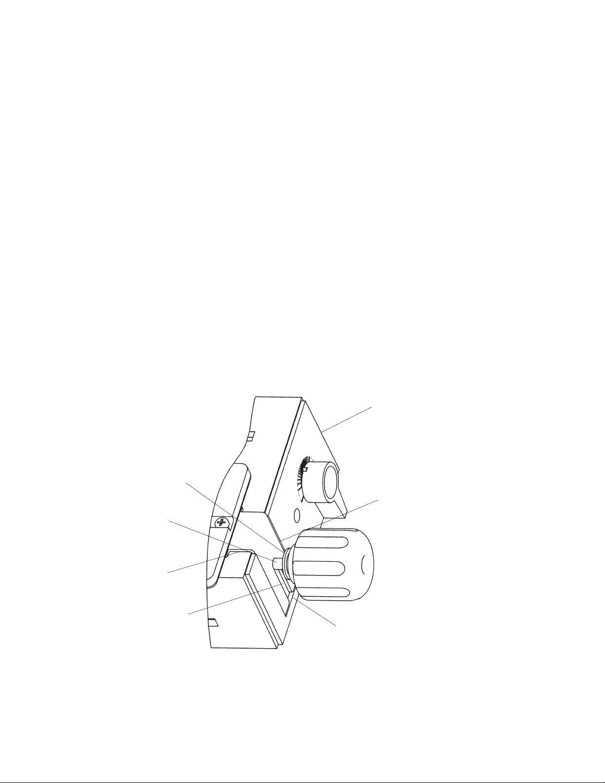
CLAMPING KNOB
DOVETAIL TEMPLATE FOR
HALF BLIND JOINTS
CLAMPING KNOB
WASHER
TEMPLATE BRACKET
MAKING DRAWERS WITH HALF BLIND RABBETED JOINTS
GENERAL PREPARATIONS
a. The length of the drawer front is 3/4" longer than the
length of the drawer back.
b. The height of the drawer front is 3/4" higher than the
height of the drawer back and drawer sides.
• IT IS EXTREMELY IMPORTANT THAT THE TEMPLATE
BE PROPERLY ALIGNED WHEN MAKING THESE
JOINTS, OR ELSE, IN ADDITION TO THE JOINT SPACING NOT BEING EQUAL, AS SHOWN IN FIGURE 60
BELOW, THE TOP SURFACES OF THE SIDES, FRONT,
AND BACK WILL NOT “LINE-UP” PROPERLY EITHER.
REFER TO THE SECTION “ALIGNMENT OF THE TEMPLATES.” (Figure 60 illustrates a Flush Dovetail Joint.)
• All other GENERAL PREPARATIONS, except as noted
below in the procedure, are the same as those used for
“MAKING DRAWERS WITH HALF BLIND FLUSH
JOINTS”.
Page 37

37
FIGURE 58 – JOINT IS TOO SHALLOW
FIGURE 59 – JOINT IS TOO DEEP
FIGURE 60 – JOINT SPACING IS NOT UNIFORM
TROUBLESHOOTING
• If the joint is too loose: INCREASE the depth of cut by
INCREASING the amount by which the router bit extends
beyond the baseplate by 1/64'’ to 1/32" and make a trial
cut. Continue adjusting until desired joint fit is attained.
• If the joint is too tight: DECREASE the depth of cut by
DECREASING the amount by which the router bit extends
beyond the baseplate by 1/64'’ to 1/32" and make a trial
cut. Continue adjusting until desired joint fit is attained.
• If the joint is too shallow: Refer to Figure 58. Loosen
the clamping knobs holding the template brackets and
move the template INWARD half the additional depth
needed by turning the cam handles. Retighten the clamping knobs.
• If the joint is too deep: Refer to Figure 59. Loosen the
clamping knobs holding the template brackets and move
the template OUTWARD by turning the cam handles half
the distance needed. Retighten the clamping knobs.
• If the joint is not uniformly spaced from top surface
of drawer: Refer to Figure 60. (See the Section "ALIGNMENT OF THE TEMPLATES".) With the template clamped
to the base, loosen the four screws securing the template
to the template brackets, and move the template slightly to
the left. Tighten the four screws and make a trial cut. If
moving the template to the left did not correct the condition, but made it worse, loosen the screws and move the
template to the right a small amount. Tighten the four
screws and make a trial cut. Continue moving the template
to the right until the condition is completely corrected.
MAKE SURE TO SECURELY TIGHTEN THE FOUR
SCREWS. If moving the template to the left improves the
condition, continue moving the template to the left until the
condition is completely corrected. Make sure the template
remains parallel to the front of the dovetail base. MAKE
SURE TO SECURELY TIGHTEN THE FOUR SCREWS.
AFTER THE TEMPLATES HAVE BEEN CORRECTLY
REALIGNED, THEY SHOULD REQUIRE NO FURTHER
ADJUSTMENTS IF THEY ARE HANDLED WITH CARE.
DRAWER
LEFT SIDE
DRAWER FRONT
SIDE
EXTENDS
OUT PAST
FRONT
SIDE
EXTENDS
OUT PAST
FRONT
DRAWER
BACK
DRAWER FRONT
DRAWER
LEFT SIDE
DRAWER
BACK
BACK
EXTENDS
OUT
PAST
SIDE
BACK
EXTENDS
OUT PAST
SIDE
SPACING GREATER
THAN DRAWER FRONT
DRAWER BACK
DRAWER LEFT SIDE
SPACING LESS THAN
DRAWER BACK
DRAWER FRONT
Page 38

38
MAKING PROJECTS WITH OPEN (THROUGH) JOINTS
• The thickness of both the front and the back (tail pieces)
must be between 3/8" and 1".
• The thickness of the sides (pin pieces) must also be
between 3/8" and 1".
• Figure 61 shows a project and the workpieces that make
it up. This figure is similar to Figure 40, except that it
shows the workpieces unassembled.
• Trial cuts are strongly recommended using scrap wood to
ensure that the final workpieces are of the desired quality.
CORNER #1 CORNER #4
CORNER #2 CORNER #3
PROJECT
RIGHT SIDE
TAILS
INSIDE OF PROJECT
SURFACE LINES UP WITH
FRONT STOP BLOCK
OUTSIDE
OF
PROJECT
PROJECT BACK
PINS
PROJECT FRONT
SURFACE LINES
UP WITH FRONT
STOP BLOCKS
OUTSIDE OF
PROJECT
PROJECT LEFT SIDE
GENERAL PREPARATIONS
a. The workpieces comprising the project, that is, front,
back, left side and right side should be cut to the proper
length, width and thickness(es).
b. Make sure that all surfaces are smooth and square with
each of the other surfaces.
c. Line up the workpieces on a flat surface, standing on
edge, as shown in Figure 62.
d. With a soft lead pencil mark the front, back and two
sides, as shown in Figure 62, also. This is to aid you
in positioning the workpieces on the Dovetail Jig, prior
to
cutting the dovetails.
e. Position both of the top stop blocks so that the "A" faces
the "middle of the base" as shown in Figure 48.
f. Position the cam handle so that the pointer points to the
center graduation as shown in Figure 48.
FIGURE 61
Page 39

39
MARK “PROJECT FRONT TOP SURFACE”
MARK “1”
MARK “4”
MARK “2”
MARK “3”
MARK “PROJECT
RIGHT SIDE TOP
SURFACE”
MARK “PROJECT
BACK OUTSIDE
SURFACE”
MARK “PROJECT
LEFT SIDE OUTSIDE
SURFACE”
MARK “PROJECT
LEFT SIDE TOP
SURFACE”
MARK “PROJECT FRONT OUTSIDE
SURFACE” (SHOWN HIDDEN)
MARK “PROJECT RIGHT SIDE OUTSIDE
SURFACE” (SHOWN HIDDEN)
MARK “PROJECT
BACK TOP SURFACE”
FIGURE 62
THE FOLLOWING DESCRIBES THE PROCEDURE TO
BE FOLLOWED FOR CUTTING THE PROJECT RIGHT
SIDE AND THE PROJECT LEFT SIDE
NOTE: THESE WORKPIECES MUST BE CUT FIRST
BECAUSE ANY JOINT FIT ADJUSTMENTS THAT MAY
BE REQUIRED CAN ONLY BE MADE WHEN CUTTING
THE PROJECT FRONT AND PROJECT BACK–THAT IS,
THE DRAWER FRONT AND THE PROJECT BACK ARE
FIT TO THE SIDES.
1. Assemble the 1/2" guide bushing to the router baseplate, as described in a previous section. This is the larger
of the two guide bushings furnished with this product
2. Install Vermont American #22501 or Magna #M91114, to
the router as described in your Router Owners Manual.
Shank engagement should be a minimum of 3/4".
MAKE SURE THAT THE ROUTER BIT
IS ALIGNED WITH OR CENTERED IN THE HOLE IN THE
GUIDE BUSHING. TO DO THIS, LOOSEN SCREWS
HOLDING BASE PLATE OR ADAPTER PLATE TO
ROUTER, CENTER GUIDE BUSHING HOLE WITH
RESPECT TO ROUTER BIT AND RETIGHTEN SCREWS
SECURELY.
CAUTION
1/2" DIA. GUIDE BUSHING
VERMONT AMERICAN #22501
OR MAGNA #M91114
STRAIGHT ROUTER BIT
WHEN SETTING THE DEPTH OF
CUT, MAKE ABSOLUTELY SURE THAT THE COLLET
NUT DOES NOT CONTACT (TOUCH) THE GUIDE BUSHING. THIS CAN CAUSE THE GUIDE BUSHING TO HEAT
UP EXCESSIVELY DURING CUTTING WHICH CAN
CAUSE DAMAGE TO THE TEMPLATE. TO CORRECT
THIS SITUATION OR PREVENT IT FROM OCCURRING,
REPOSITION THE ROUTER BIT IN THE ROUTER.
CAUTION
Page 40

40
3. Adjust the depth of cut. The depth of cut for an OPEN
DOVETAIL JOINT is equal to the thickness of the mating
part. That is:
FOR CORNER #1 OF THE PROJECT RIGHT SIDE
and FOR CORNER #4 OF THE PROJECT LEFT SIDE,
THE DEPTH OF CUT IS EQUAL TO THE THICKNESS
OF THE PROJECT FRONT.
FOR CORNER #2 OF THE PROJECT RIGHT SIDE
and FOR CORNER #3 OF THE PROJECT LEFT SIDE,
THE DEPTH OF CUT IS EQUAL TO THE THICKNESS
OF THE PROJECT BACK.
Use the depth gauge on the base of the Dovetail Jig, as
described in a previous section, as a starting point.
4. At this point it will be necessary for you to make a top
back-up board. The reasons for the top back-up board are
to minimize splintering and to provide support for the
template. The top back-up board is a scrap piece of wood
having the following dimensions:
LENGTH: 6" to 8", sufficient length so that it can
clamped by the top clamping bar and be used more
than once;
WIDTH: 2" wider than the width of the project sides;
THICKNESS: 1/8" to 1/4" thicker than the thickness of
the project sides; this to prevent "ACCIDENTALLY"
cutting into the dovetail base.
This can also be accomplished by using more than one
piece of scrap as long as the resultant length, width and
thickness are as described.
5. TO CUT CORNER #1 OF THE PROJECT RIGHT SIDE,
position the top back-up board on top of the base so that it
lines up with the front of the base and abuts to the right
top stop block as shown in Figure 63.
FIGURE 63
AUXILIARY TEMPLATE
SUPPORT (AS NEEDED)
TOP BACK-UP BOARD
TOP OF THE BASE
FRONT OF THE BASE
FRONT BACK-UP BOARD
“OUTSIDE SURFACE” SHOULD BE VISIBLE ON THIS SURFACE
BEFORE POSITIONING THE FRONT BACK-UP BOARD
PROJECT
RIGHT SIDE OR
PROJECT LEFT
SIDE
NOTE: BACK-UP BOARDS ARE USED TO MINIMIZE
SPLINTERING OF PROJECT PIECES AND TO KEEP
ROUTER BIT FROM DAMAGING THE DOVETAIL JIG.
6. Lightly clamp the back-up board in place.
7. Position the project side against the front of the base so
that the top surface abuts the right front stop block. The
use of a front back-up board at this step is also recommended. It is positioned between the project side and the
clamping bar as shown in Figure 63. The front back-up
board should have the following approximate dimensions
LENGTH: 6" to 8", sufficient length so that it can be
clamped by the front clamping bar and be used more
than once;
WIDTH: 1" to 2" wider than the width of the sides;
THICKNESS: 1/4" to 1/2".
THE OUTSIDE OF THE PROJECT SIDE FACES AWAY
FROM THE FRONT OF THE BASE
The words "OUTSIDE SURFACE" marked in (d) in the
Section, GENERAL PREPARATIONS, should have been
visible before the front back-up board was put in place
8. Line up the workpieces so that the end of the project
side and back-up boards line up as shown in Figure 63.
9. Securely clamp the project side and the front back-up
board to the front of the base.
10. Securely clamp the top back-up board to the top of the
base.
11. Make sure that the parts remain lined up.
12. Assemble the DOVETAIL TEMPLATE FOR OPEN
(THROUGH) JOINTS to the Dovetail Jig so that THE TEMPLATE BRACKETS FIT BETWEEN THE WASHERS AND
THE TEMPLATE SUPPORTS as shown Figure 64; it will
be necessary to loosen the clamping knobs at the ends of
the base to do this.
Page 41

41
FIGURE 64
FIGURE 65
CLAMPING
KNOB
DOVETAIL TEMPLATE FOR
OPEN (THROUGH) JOINTS
TEMPLATE BRACKET
CLAMPING KNOB
WASHER
TOP BACK-UP BOARD
FRONT BACK-UP BOARD
PROJECT RIGHT SIDE OR
PROJECT LEFT SIDE
DOVETAIL CUTS
THIS CAN CAUSE DAMAGE TO THE DOVETAIL JIG;
OR LOSS OF CONTROL OF THE ROUTER WHICH CAN
RESULT IN SERIOUS BODILY INJURY. A TRIAL RUN
WITH THE ROUTER TURNED OFF AND UNPLUGGED
FROM THE ELECTRICAL OUTLET IS STRONGLY
RECOMMENDED.
16. TURN THE ROUTER ON.
17. Cut the dovetail by moving the router from LEFT TO
RIGHT, with the guide bushing following the template. DO
NOT FORCE ANYTHING; MOVE THE ROUTER IN SLOW
AND SMOOTH FASHION.
18. To ensure a smooth and uniform joint, retrace the previous cut by moving the router from RIGHT TO LEFT with
the guide bushing again following the template.
13. Make sure that the template is oriented as shown in
Figure 65.
14. Make sure that the template is flush and parallel with
the workpieces clamped to base. For narrow project sides,
the use of an auxiliary support for the template is recommended. Its purpose is to aid in supporting the router while
cutting. It can be made from a piece of scrap wood; but its
thickness must be the same as the top back-up board.
(Refer to Figure 63).
15. Clamp the template in place by tightening the clamping
knobs.
BEFORE MAKING ANY CUTS MAKE
SURE THAT THE BIT WILL NOT CUT INTO THE BASE
OR ANY OTHER COMPONENT OF THE DOVETAIL JIG.
CAUTION
Page 42

42
TOP BACK-UP BOARD
TOP OF THE BASE
AUXILIARY TEMPLATE SUPPORT (AS NEEDED)
FRONT OF THE BASE
FRONT BACK-UP BOARD
“OUTSIDE SURFACE” SHOULD BE
VISIBLE ON THIS SURFACE BEFORE POSITIONING THE FRONT BACK-UP BOARD
PROJECT
RIGHT SIDE
OR PROJECT
LEFT SIDE
TOP BACK-UP BOARD
FRONT
BACK-UP
BOARD
DOVETAIL CUTS
FIGURE 66
FIGURE 67
NEVER LIFT THE ROUTER
UPWARDS WHEN THE ROUTER IS ON AND THE
ROUTER BIT ROTATING OR WHEN THE GUIDE BUSHING IS NEAR TO OR TOUCHING THE TEMPLATE. THIS
CAN CAUSE DAMAGE TO THE DOVETAIL JIG; OR
LOSS OF CONTROL OF THE ROUTER WHICH CAN
RESULT IN SERIOUS BODILY INJURY.
19. After the cut has been made, the workpieces should
look like those illustrated in Figure 67.
20. Remove the workpiece and back-up boards from the
Dovetail Jig.
21. The back-up boards can be reused if the cut portions
of boards are cut off. AFTER BEING REUSED UNTIL
THEY NO LONGER SERVE THEIR INTENDED FUNCTION, NEW BACK-UP BOARDS MUST BE MADE.
22. TO CUT CORNER #3 OF THE PROJECT LEFT SIDE,
position the top back-up board on top of the base so that it
lines with the front of the base and abuts the right top stop
block as shown in Figure 63.
23. Continue as Steps 6 through 23.
24. TO CUT CORNER #2 OF THE PROJECT RIGHT
SIDE, position the top back-up board on top of the base so
that it lines up with the front of the base and abuts the left
top stop block as shown above in Figure 66.
25. Lightly clamp the back-up board in place.
26. Position the project side against the front of the base
so that the top surface abuts the left front stop block. The
use of a front back-up board at this step is also recommended. It is positioned between the project side and the
clamping bar as shown in Figure 67. The front back-up
board is described in Step 6 on page 40.
27. Continue as in Steps 8 through 19 above.
28. After the cuts have been made, the workpieces should
look like those illustrated in Figure 61.
29. Remove the workpiece and the back-up boards from
the Dovetail Jig.
NOTE: THE BACK–UP BOARDS ARE REUSABLE.
CAUTION
30. TO CUT CORNER #4 OF THE PROJECT LEFT SIDE,
position the top back-up board on top of the base so that it
lines up with the front of the base and abuts the left top
stop block as shown is Figure 66.
31. Continue as Steps 27 through 32 above.
32. At this stage the project sides should look like those
illustrated in Figure 61.
Page 43

43
THE FOLLOWING DESCRIBES THE PROCEDURE TO
BE FOLLOWED FOR CUTTING THE PROJECT FRONT
AND BACK
NOTE: Any joint fit adjustments that may be required
can only be made when cutting the project front and
back pieces. That is, adjustments are made to project
front and back pieces ONLY, not to the side pieces.
1. Assemble the .40" guide bushing to the router baseplate,
as described in a previous section. This is the smaller of
the two guide bushings furnished with this product.
2. Install Vermont American #22437 or Magna #M91016
straight router bit, to the router as described in your Router
Owners Manual. Shank engagement should be a minimum
of 3/4".
TOP BACK-UP BOARD
TOP OF THE BASE
PROJECT
FRONT OR
PROJECT BACK
FRONT BACK-UP BOARD
“OUTSIDE SURFACE” SHOULD BE VISIBLE ON THIS SURFACE BEFORE POSITIONING THE FRONT BACK-UP BOARD
FRONT OF THE BASE
AUXILIARY TEMPLATE
SUPPORT (AS NEEDED)
MAKE SURE THAT THE ROUTER BIT
IS ALIGNED WITH OR CENTERED IN THE HOLE IN THE
GUIDE BUSHING. TO DO THIS, LOOSEN SCREWS
HOLDING BASE PLATE OR ADAPTER PLATE TO
ROUTER, CENTER GUIDE BUSHING HOLE WITH
RESPECT TO ROUTER BIT AND RETIGHTEN SCREWS
SECURELY.
WHEN SETTING THE DEPTH OF
CUT, MAKE ABSOLUTELY SURE THAT THE COLLET
NUT DOES NOT CONTACT (TOUCH) THE GUIDE BUSHING. THIS CAN CAUSE THE GUIDE BUSHING TO HEAT
UP EXCESSIVELY DURING CUTTING WHICH CAN
CAUTION
CAUTION
.40" DIA. GUIDE BUSHING
VERMONT
AMERICAN
#22437 OR
MAGNA #M91016
STRAIGHT
ROUTER BIT
CAUSE DAMAGE TO THE TEMPLATE. TO CORRECT
THIS SITUATION OR PREVENT IT FROM OCCURRING,
REPOSITION THE ROUTER BIT IN THE ROUTER
3. Adjust the depth of cut. The depth of cut for an OPEN
DOVETAIL JOINT is equal to the thickness of the mating
part. That is:
FOR CORNER #1 OF THE PROJECT FRONT, THE
DEPTH OF CUT IS EQUAL TO THE THICKNESS OF
THE PROJECT RIGHT SIDE.
FOR CORNER #4 OF THE PROJECT FRONT, THE
DEPTH OF CUT IS EQUAL TO THE THICKNESS OF
THE PROJECT LEFT SIDE.
FOR CORNER #2 OF THE PROJECT BACK, THE
DEPTH OF CUT IS EQUAL TO THE THICKNESS OF
THE PROJECT RIGHT SIDE.
FOR CORNER #3 OF THE PROJECT BACK, THE
DEPTH OF CUT IS EQUAL TO THE THICKNESS OF
THE PROJECT LEFT SIDE.
Use the depth gauge on the base of the Dovetail Jig, as
described in a previous section, as a starting point
4. At this point it will be necessary for you to make a top
back-up board. The reasons for the top back-up board are
to minimize splintering, provide support for the template
and prevent damage to the Dovetail Jig. The top back-up
board is a scrap piece of wood having the following
dimensions:
LENGTH: 6" to 8", sufficient length so that it can be
clamped by the top clamping bar and be used more
than once;
WIDTH: 2" wider than the width of the project front
(or back)
THICKNESS: 1/8" to 1/4" thicker than the thickness
of the project front (or back); THIS IS TO PREVENT
ACCIDENTALLY CUTTING INTO THE DOVETAIL JIG.
This can also be accomplished by using more than one
piece of scrap as long as the resultant length, width, and
thickness are as described.
5. TO CUT CORNER #1 OF THE PROJECT FRONT,
position the top back-up board on top of the base so that it
lines up with the front of the base and abuts the left top
stop block as shown in Figure 68.
FIGURE 68
Page 44

44
DOVETAIL TEMPLATE FOR OPEN (THROUGH) JOINTS
CLAMPING KNOB
TEMPLATE
BRACKET
CLAMPING KNOB
WASHER
6. Lightly clamp the back-up board in place.
7. Position the project front (or back) against the front of
the base so that the top surface abuts the left front stop
block. The use of a front back-up board at this step is also
recommended. It is positioned between the project front
(or back) and the clamping bar as shown in Figure 68. The
front back-up board should have the following approximate
dimensions:
LENGTH: 6" to 8", sufficient length so that it can clamped
by the front clamping bar and be used more than once;
WIDTH: 1" to 2" wider than the width of the front (or
back);
THICKNESS: 1/4" to 1/2".
THE OUTSIDE OF THE PROJECT FRONT (OR BACK)
FACES AWAY FROM THE FRONT OF THE BASE.
The words "OUTSIDE SURFACE" marked in (d) in the
Section, GENERAL PREPARATIONS, should have been
visible before the front back-up board was put in place
8. Line up the workpieces so that the end of the project
front (or back) and back-up boards line up as shown in
Figure 68 .
9. Securely clamp the project front(or back) and front backup board to the front of the base.
10. Securely clamp the top back-up board to the top of the
base.
11. Make sure that the parts remain lined up.
12. Assemble the DOVETAIL TEMPLATE FOR OPEN
(THROUGH) JOINTS to the Dovetail Jig so that THE TEMPLATE BRACKETS FIT BETWEEN THE WASHERS AND
THE TEMPLATE SUPPORTS as shown above in Figure
69; it will be necessary to loosen the clamping knobs at
the ends of the base to do this.
13. Make sure that the template is oriented as shown in
Figure 69.
14. Make sure that the template is flush and parallel with
the workpieces clamped to base. For narrow project fronts
(or backs), the use of an auxiliary support for the template
is recommended. Its purpose is to aid in supporting the
router while cutting. It can be made from a piece of scrap
wood; but its thickness must be the same as the top backup board. (Refer to Figure 68.)
15. Clamp the template in place by tightening the clamping
knobs.
FIGURE 69
FIGURE 70
BEFORE MAKING ANY CUTS MAKE
SURE THAT THE BIT WILL NOT CUT INTO THE BASE
OR ANY OTHER COMPONENT OF THE DOVETAIL JIG.
THIS CAN CAUSE DAMAGE TO THE DOVETAIL JIG.
16. TURN THE ROUTER ON.
17. Cut the dovetail by moving the router from LEFT TO
RIGHT, with the guide bushing following the template. DO
NOT FORCE ANYTHING; MOVE THE ROUTER IN SLOW
AND SMOOTH FASHION.
18. To ensure a smooth and uniform joint, retrace the previous cut by moving the router from RIGHT TO LEFT with
the guide bushing again following the template.
19. MAKE SURE THAT ALL OF THE MATERIAL IS CUT
AWAY; FREE ROUTING MAY BE REQUIRED TO
ACCOMPLISH THIS. EXTRA CARE IS REQUIRED IN
CONTROLLING THE ROUTER MOVEMENT WHILE
DOING FREE ROUTING. (Refer to Figure 70).
CAUTION
TOP BACK-UP
BOARD
DOVETAIL
CUTS
DRAWER FRONT
OR DRAWER BACK
Page 45

45
AUXILIARY TEMPLATE SUPPORT
(AS NEEDED)
TOP OF THE BASE
TOP BACK-UP BOARD
PROJECT FRONT OR
PROJECT BACK
FRONT OF THE BASE
FRONT BACK-UP BOARD
“OUTSIDE SURFACE” SHOULD BE VISIBLE ON THIS SURFACE
BEFORE POSITIONING THE FRONT BACK-UP BOARD
FIGURE 71
NEVER LIFT THE ROUTER
UPWARDS WHEN THE ROUTER IS ON AND THE
ROUTER BIT ROTATING OR WHEN THE GUIDE BUSHING IS NEAR TO OR TOUCHING THE TEMPLATE.
20. After the cut has been made, the project back and front
should look like those illustrated in Figure 61.
21. Remove the workpiece and back-up boards from the
Dovetail Jig.
22. The back-up boards can be reused if the cut portions
of boards are cut off. AFTER BEING REUSED UNTIL
THEY NO LONGER SERVE THEIR INTENDED FUNCTION, NEW BACK-UP BOARDS MUST BE MADE.
23. TO CUT CORNER #3 OF THE PROJECT BACK,
position the top back-up board on top of the base so that it
lines with the front of the base and abuts the left top stop
block as shown in Figure 68.
24. Continue as Steps 6 through 24.
25. TO CUT CORNER #4 OF THE PROJECT FRONT,
position the top back-up board on top of the base so that it
lines up with the front of the base and abuts the right top
stop block as shown in Figure 71.
26. Lightly clamp the back-up board in place.
27. Position the project front (or back) against the front of
CAUTION
the base so that the top surface abuts the right front stop
block. The use of a front back-up board at this step
is also recommended. It is positioned between the
drawer front (or back) and the clamping bar as shown in
Figure 71. The front back-up board is described in Step 7
above.
28. Continue as in Steps 8 through 20 above.
29. After the cuts have made, the workpieces should look
like those illustrated in Figure 61.
30. Remove the workpiece and the back-up boards from
the Dovetail Jig.
NOTE: THE BACK–UP BOARDS ARE REUSABLE.
31. TO CUT CORNER #2 OF THE PROJECT BACK,
position the top back-up board on top of the base so that it
lines up with the front of the base and abuts the right top
stop block as shown is Figure 71.
32. Continue as Steps 28 through 32 above.
33. The finished project front, back, and sides should look
like those illustrated in Figure 61.
34. Check how the workpieces fit together. Some adjustments may be necessary. Refer to the section,
TROUBLESHOOTING.
• Your project is now ready to be glued together.
• Remove the pencil markings by light sanding or with a
soft eraser after the parts have been glued together.
Page 46

46
TROUBLESHOOTING
• If the joint is too loose: This adjustment can only be
made when cutting either the front or the back (tail pieces).
Loosen the clamping knobs holding the template brackets
and move the template OUTWARD by turning the cam
handles. Continue adjusting until desired joint fit is
attained. Retighten the clamping knobs.
• If the joint is too tight: This adjustment too can only be
made when cutting either the front or the back (tail pieces).
Loosen the clamping knobs holding the template brackets
and move the template INWARD by turning the cam handles. Continue adjusting until desired joint fit is attained.
Retighten the clamping knobs.
• If the joint is too shallow: Refer to Figure 72.
INCREASE the depth of cut of the router bit. This adjustment can be made when cutting the front, the back, (tail
pieces) and the sides (pin pieces).
• If the joint is too deep: Refer to Figure 73.
DECREASE the depth of cut of the router bit. This adjustment too can be made when cutting the front, the back,
(tail pieces) and the sides (pin pieces).
• If the joint is not uniformly spaced from top surface
of drawer: Refer to Figure 74. (See the Section “ALIGNMENT OF THE TEMPLATES”.) With the template
clamped to the base, loosen the four screws securing the
template to the template brackets, and move the template
slightly to the left. Tighten the four screws and make a trial
cut. If moving the template to the left did not correct the
condition, but made it worse, loosen the screws and move
the template to the right a small amount. Make sure the
template remains parallel to the front of the dovetail base.
Tighten the four screws and make a trial cut. Continue
moving the template to the right until the condition is
completely corrected. PROPER ALIGNMENT OF THE
TEMPLATES TO THE TEMPLATE BRACKETS IS CRITICAL FOR JOINT UNIFORMITY. ONCE THIS IS ACCOMPLISHED CORRECTLY, IT SHOULD NOT NEED
ADJUSTMENTS AGAIN. MAKE SURE TO SECURELY
TIGHTEN THE FOUR SCREWS. AFTER THE TEMPLATES HAVE BEEN CORRECTLY REALIGNED, THEY
SHOULD REQUIRE NO FURTHER ADJUSTMENTS IF
THEY ARE HANDLED WITH CARE.
PROJECT
FRONT
FRONT EXTENDS
OUT PAST SIDE
SIDE
EXTENDS
OUT PAST
FRONT
SIDE
EXTENDS
OUT PAST
BACK
BACK EXTENDS
OUT PAST SIDE
PROJECT
BACK
PROJECT
LEFT SIDE
PROJECT
FRONT
SIDE EXTENDS
OUT PAST FRONT
FRONT
EXTENDS
OUT PAST
SIDE
BACK
EXTENDS
OUT PAST
SIDE
PROJECT
BACK
PROJECT
LEFT SIDE
FRONT
(TAIL PIECE)
SPACING
GREATER THAN
BACK
SPACING LESS
THAN FRONT
BACK
(TAIL PIECE)
SIDE
(PIN PIECE)
SIDE EXTENDS
OUT PAST BACK
FIGURE 72 – JOINT IS TOO SHALLOW
FIGURE 73 – JOINT IS TOO DEEP
FIGURE 74 – JOINT SPACING IS NOT EQUAL
Page 47

47
PARTS LIST
PARTS LIST
KEY PART NO. DESCRIPTION QTY
1 29LD-879-1 Deluxe Dovetail Base 1
2 29LD-880-1 Dovetail Template (Blind Joint) 1
3 29LD-881-1 Dovetail Template (Open Joint) 1
4 29LD-882 Template Support (Right Side) 1
5 29LD-883 Template Support (Left Side) 1
6 29LD-884-1 Cam Handle 2
7 29LD-885-1 Front Stop Block 2
8 29LD-886-1 Top Stop Block 2
9 29LD-887 Clamping Bar End Cap 4
10 29LD-888-1 Retainer 1
11 29LD-889-1 Bolt Support 4
12 29LD-890-1 Clamping Knob 6
13 29LD-891 Clamping Bar 2
14 29LD-892 Pivot Shaft 1
15 29LD-895 Template Bracket 4
16 29LD-896 Template Stiffener 2
17 29LD-899 Guide Bushing Assembly (.4" Dia.) 1
18 29LD-900 Guide Bushing Assembly (1/2" Dia.) 1
19 29LD-901 Compression Spring 4
20 45A-414 Product Label (Clamping Bar) 1
21 45A-416 Label (Template–Blind) 1
22 45A-417 Label (Template–Open) 1
23 45A-415 Warning Label (Clamping Bar) 1
KEY PART NO. DESCRIPTION QTY
24 29L-469-13 #10-32 X 5/8" lg. Panhead Machine Screw 4
25 29L-469-14 #10-32 X 3/8" lg. Panhead Machine Screw 8
26 29L-469-15 #8-36 X 3/16" lg. Panhead Machine Screw 10
27 29LD-841-2 #10-32 X 5/8" lg. Flat Head Machine Screw 2
28 29LD-841-3 #10-32 X 7/8" lg. Flat Head Machine Screw 2
29 29LD-841-4 #10-32 X 3/8" lg. Flat Head Machine Screw 3
30 29L-684-6 #10-16 X 1/2" lg. Panhead Tapping Screw 1
31 29L-684-7 #10-16 X 1" lg. Panhead Tapping Screw 3
32 29A-310-15 5/16-18 X 4-1/2" lg. RD HD SQ Neck Bolt 2
33 29A-310-16 5/16-18 X 3-1/2" lg. RD HD SQ Neck Bolt 2
34 29A-310-17 5/16-18 X 2" lg. RD HD SQ Neck Bolt 2
35 29A-242-12 #10-32 Hex Machine Screw Nut 4
36 29A-242-13 5/16-18 Hex Machine Screw Nut 2
37 29A-306-20 13/64" ID X 15/32" OD X 3/64"
Thick Washer 13
38 29A-306-40 11/32" ID X 7/8" OD X 1/16" Thick Washer 8
39 29LD-930 11/32" ID X 7/8" OD Thin Nylon Washer 4
40 29LD-969 5/16" ID X 7/8" OD Thick Nylon Washer 4
41 29LCN-1005 Spring Retainer 4
42 29A-368-1 #8 Countersunk Bushing 4
43 29A-368-2 #10 Countersunk Bushing 4
44 29GD-375 Router Adapter Plate 1
45 VA #25500 1/2" VA Dovetail Router Bit 1
-- 45LCN-72 Instruction Manual 1
PARTS LIST FOR VERMONT AMERICAN INDUSTRIAL DOVETAIL JIG MODEL NO. 23461
Key No.’s 29, 42, 43, 44, and 45 along with four of Key No. 37 are furnished loose and unassembled.
Page 48

48
12
12
4
6
7
7
8
8
1
10
14
5
6
BASE ASSEMBLY
TEMPLATE SUPPORT ASSEMBLY
Page 49

49
45
43
12
12
12
12
20
13
13
9
19
19
11
11
23
42
44
CLAMPING ASSEMBLY
ROUTER ADAPTER PLATE
9
9
19
19
11
11
9
Page 50

50
TEMPLATES
FASTENERS
18
15
15
35 36
16
15
15
17
3
2
16
22
21
37 38 39
32 33 34
41
40
27 28 29
24 25 26
30 31
Page 51

51
NOTES
Page 52

Printed in U.S.A.
08/99
Manual No. 45LCN-72
When corresponding, always give the following
information as shown in the list.
1. The PART NUMBER
2. The PART DESCRIPTION
3. The MODEL NUMBER: 23461
4. The ITEM NAME – INDUSTRIAL DOVETAIL JIG
To obtain a copy of this Manual in French, call
the following toll-free number 1-800-742-3869.
To obtain a copy of this Manual in Spanish, call
the following toll-free number 1-800-742-3869.
 Loading...