

Page 1
OWNER’S MANUAL
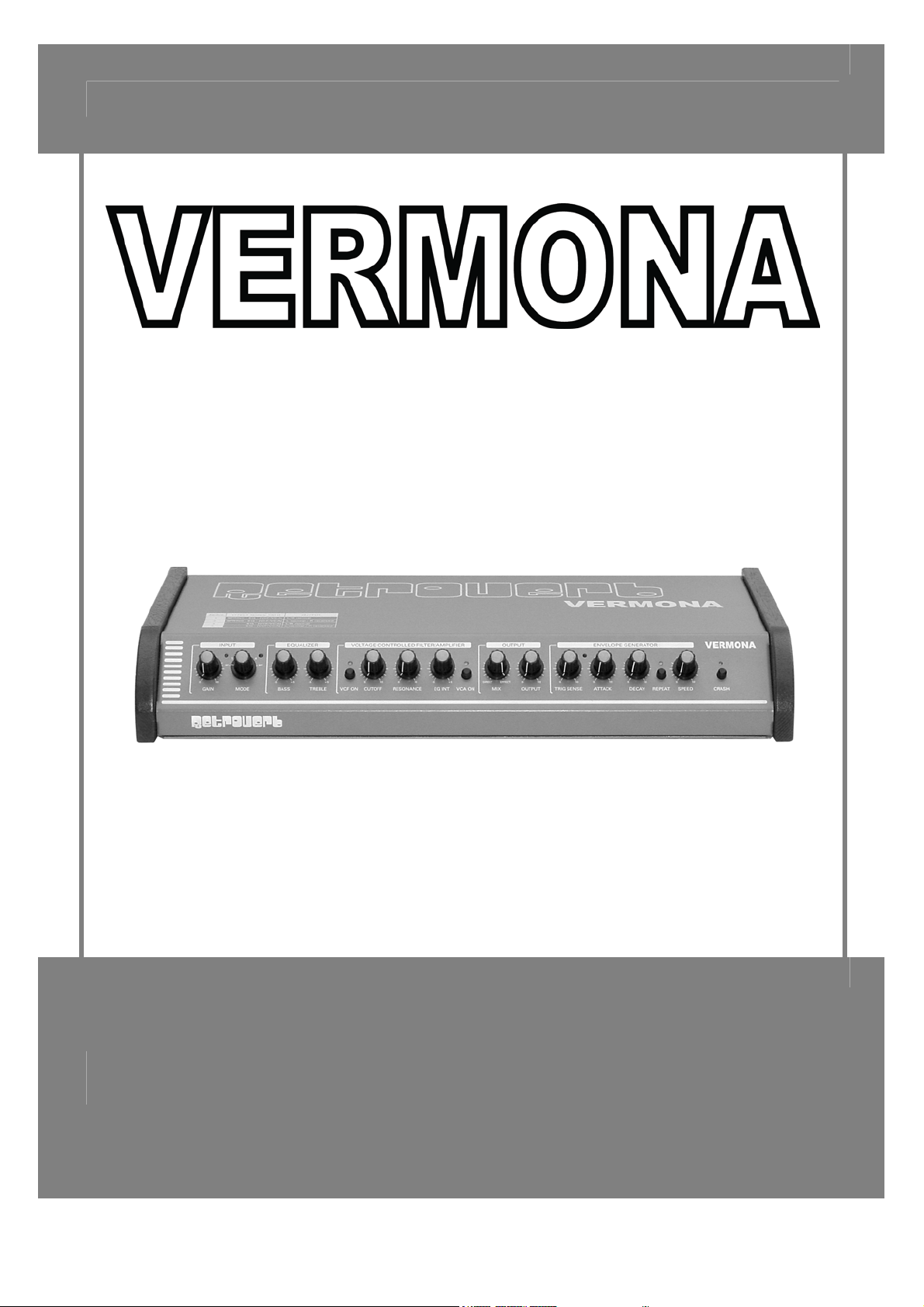
„RETROVERB“
Page 2

Foreword
Thank you for purchasing the Retroverb – spring reverb.
The Retroverb is an extremely flexible spring reverb unit, which can generate the typical reverb effects of its
classic ancestors as well as very unusual sound creations.
Although the Retroverb has a well organised and clear user interface, and the functions of the switches,
potentiometers and jacks seem easy to understand, we would like you to please take a glance through this
manual to become familiar with the functions and possibilities.
We wish you much fun with your Retroverb,
The VERMONA team.
Table of Contents
Foreword ................................................................................................................................................................. 2
Table of Contents .................................................................................................................................................... 2
General.................................................................................................................................................................... 3
Control Features...................................................................................................................................................... 5
Input section......................................................................................................................................................... 5
Voltage Controlled Filter / Amplifier...................................................................................................................... 6
Envelope Generator............................................................................................................................................. 7
Output .................................................................................................................................................................. 8
In- and Outputs .................................................................................................................................................... 8
CV / Pedal and Trigger Inputs.............................................................................................................................. 9
Footswitch Inputs ............................................................................................................................................... 10
CRASH .............................................................................................................................................................. 10
Declaration of conformity....................................................................................................................................... 11
Page 3

General
Important safety information
The following safety precautions must be observed during all phases of operation, service and repair of this equipment. Failure to comply with
these precautions or with specific warnings in this manual violates safety standards of design, manufacture and intended use of this equipment.
The manufacturer assumes no liability for the customer’s failure to comply with these requirements!
Ground and power connection
To prevent the risk of electrical shock, this equipment must be grounded. The factory setting for power is already made for each country (115V
AC, 230V AC). An individual setting is not allowed by virtue of safety reasons. This modification must be done by qualified personnel only!
Voltage peak
The units are equipped to manage voltage peaks, which are often generated at live situations. When using the units with unstable voltage, please
make sure that the device is grounded.
Use near explosive goods
The units should not be used near easily flammable or explosive goods.
Dampness
The units should not be used in damp or wet places. Make sure the unit is not in humid atmospheres, because this could cause condensation
within the unit.
WARNING: Risk of electrical shock!
Connections
Only use cables, plugs and adapters, which do not affect the normal use of the unit.
Cooling System
The unit should not be used near heating or warm or hot fans. When using the unit in a rack or wall system, make sure that the unit has enough
space to let the generated heat dissolve.
Cleaning
Please clean the unit only with a dry duster. Do not use sharp cleaning fluids or water!
Spare parts or modifications
Modification instructions and schematic information should only be used from service departments of our official authorized VERMONA dealers.
To prevent the risk of electrical shock, please do not open or modify the unit yourself. Before opening the unit always disconnect the power
lead/AC Adapter. Opening or modifying the units causes the loss of warranty claims!
Warranty
The manufacturer warrants this product to be free of defects in material and/or workmanship. The manufacturer’s warranty does not apply to
products that have been damaged due to and/or subjected to improper handling by shipping companies (forwarders), negligence, accidents,
improper use or alteration not authorized by the manufacturer.
This warranty is in lieu of an excluded all other warranties, expressed or implied. The manufacturer will not be liable for incidental or consequential
loss or damage whatsoever, whether based upon allegations or negligence, breach of warranty, or otherwise. This disclaimer of incidental or
consequential damages includes, but is not limited to, property damages, loss of profits, loss of time or other losses or inconvenient resulting from
any defect in the material or workmanship of this product or any other connection with the purchase, operation or use of this product.
Technical changes
All changes, which improve the technical features of the units, can be made without subjective notice by the manufacturer.
- Page 3 -
Page 4

Getting Started
Unpacking
All VERMONA devices are checked and tested carefully before packaging. In spite of the specially designed
cartons and the solid build quality of the devices, damages during transportation are possible. Please check the
unit after receipt for visible damage.
Please do not discard the original packing! Use it for shipping the unit again, should this be necessary.
Inventory
The VERMONA Retroverb comes complete with:
• The VERMONA Retroverb
• AC 12V / 830mA power supply
• This manual
Please ensure all the items above are included. If something is missing contact your local dealer.
Connections
• Connect the outputs of your signal source (i.e. synthesizer, guitar, etc.) with the inputs of the
RETROVERB.
• Connect the outputs of the Retroverb with the inputs of your mixing console, amplifier, etc.
• Connect the included power supply to the 12V AC jack of the Retroverb and an outlet.
• Switch on the Retroverb.
Use the Retroverb only with the included power supply 12V AC / 830 mA.
Before connecting and disconnecting the Retroverb to a power supply, turn your amps volume all the way down to
avoid damage due to on/off switching noises!
- Page 4 -
Page 5

Control Features
Input section
Here you’ll find the GAIN controller and the MODE switch with their independent
LED’s.
The GAIN controller sets the input level, the GAIN LED lights up as soon as the
signal becomes overdriven.
You should ensure you set an optimal input level, where only peaks are
indicated by the flashing LED. If the input level is set to low, triggering the
envelope generator by the audio signal will not function as it should. (see page
7).
The MODE switch sets the general manner of how the input signal will be
processed. Besides the four possible modes, the MODE switch includes the BYPASS function (on two positions:
first and last), which routes the input signal directly to the outputs of the Retroverb.
The table on the top of the Retroverb shows the effect signal flow for the different modes:
MODE EFFECT SIGNAL PATH OUTPUT
1 SPRING – EQ – [VCF / VCA] L / R normal
2 SPRING – EQ – [VCF / VCA] L normal / R reversed
3 EQ – [VCF / VCA] L / R normal
4 EQ – [VCF / VCA] L normal / R reversed
Mode 1 and 2
In these modes, the effect signal passes through the spring module, the equalizer and the VCF / VCA section.
After being mixed with the original signal (MIX controller) it is sent to both outputs (L / R).
In mode 2, the phase of the right channel is reversed, which generates richer reverb effects due to random
annulments of frequencies.
In Mode 1 both outputs drive the same signal in the same way.
Mode 3 and 4
Modes 3 and 4 are similar to modes 1 and 2 with only one difference: The ACCUTRONICS spring reverb unit is
taken out of the signal flow. So the signal will be refined by the equalizer and / or the VCF / VCA section. In this
mode you won’t get reverb effects, but some interesting filter-, wahwah- and tremolo-effects.
The phase of the right output is also reversed in mode 4.
Note: In mode 4 it could occur that you won’t hear any signal at the output by the left and the right channel
cancelling each other out. Change to mode 3 in this case!
.
- Page 5 -
Page 6

Equalizer
With the two-band equalizer you can change the color of the reverb sound. In the
signal flow it is directly after the spring reverb unit (only in mode 1 and 2).
It is equipped with BASS and TREBLE controls for changing the levels for low and
high frequencies at +/- 15 dB.
Voltage Controlled Filter / Amplifier
The VCF / VCA section includes a complete
analogue filter and a voltage controlled amplifier.
Voltage Controlled Filter
The filter of the Retroverb is a voltage controlled
12dB-lowpass filter. It is activated or deactivated with
the VCF ON switch.
CUTOFF frequency and RESONANCE can be
adjusted with the corresponding controllers. The EG
INT controller, which works in a positive and
negative direction, sets the amount for the ATTACK-DECAY envelope for modulating the CUTOFF frequency. It’s
also possible to change the CUTOFF frequency with an external control voltage (see page 9).
Low-pass filter
A low-pass filter dampens frequencies that lie above a
defined frequency. Frequencies below that so-called
CUTOFF frequency can pass through the filter
unaffected.
If the filters output is routed back to its input, the
frequencies around the CUTOFF frequency are
amplified. This is the filters so-called RESONANCE.
- Page 6 -
Page 7

Voltage Controlled Amplifier
The voltage controlled amplifier, amplifies the input signal depending on it’s control voltage. This means a high
control voltage results in a high amplification, therefore on the VCA’s output you’ll get a high volume. Contrariwise
a low control voltage means a low amplification and therefore a low output signal.
The necessary control voltage for the VCA comes from an envelope generator.
The VCA is activated or deactivated with the VCA ON switch.
Envelope Generator
The ATTACK-DECAY envelope can modulate
the voltage controlled filter or / and the voltage
controlled amplifier.
An envelope generator generates a control voltage
which changes its value in temporal progression.
The ATTACK phase is the time which is needed to
raise the voltage from 0% to 100%.
The DECAY phase is the time which is needed to
decrease back down to 0%.
ATTACK and DECAY times can be set with the
corresponding controllers.
The envelope can be triggered from different sources:
The input signal
When the input signal reaches a special level (threshold), the envelope will be started. This sensitivity (threshold)
can be set with the TRIG SENSE controller. If this controller is set to the zero position, the envelope won’t be
triggered. The more it is raised clockwise, the more sensitive its reaction to the input signal will be.
An additional audio signal (audio trigger)
An additional audio signal can be fed in the trig jack “EG” on the rear of the Retroverb. The sensitivity of this
signal can be adjusted with its corresponding trimmer.
A Gate signal
The same trig jack can also be fed with a standard Gate signal (positive flank) as it comes from modular systems
or analog synthesizers.
- Page 7 -
Page 8

An internal Clock
The REPEAT switch activates an internal clock whose speed can be set with the SPEED controller. The envelope
will then be retriggered.
The REPEAT LED shows the speed of the clock, in deactivated (light brightness) and activated mode (dark
brightness).
As soon as the REPEAT function is activated, the envelope does not react to any other trigger signal.
Note: If the speed of the Clock is faster than the envelopes ATTACK- and DECAY times, the envelope will be cut.
Output
The MIX controller sets the proportion between the direct and effected signal. If
the controller is set to DIRECT, only the unrefined original signal can be heard on
the Retroverbs outputs. If that is the case, the CRASH function has no effect.
OUTPUT sets the output level.
In- and Outputs
INPUT
The Retroverb can be fed with mono- as well as stereo signals. Stereo signals will be converted to a mono signal
internally.
The MONO/R jack works with mono signals, STEREO / L is a stereo jack.
- Page 8 -
Page 9

OUTPUT
The Outputs L / R are mono jacks. The signal on the right channel is phase reversed in modes 2 and 4,
CV / Pedal and Trigger Inputs
CV / PEDAL
You can connect an external control voltage or an
expression / volume pedal to this jack for controlling
the CUTOFF frequency of the filter. The intensity
can be adjusted with the corresponding INT
trimmer.
For connecting a CV source i.e. from a modular system or an analogue synthesizer, you need a simple mono
cable:
To connect a Volume pedal a Y-cable is necessary:
Audio Trigger / GATE
These inputs are responsible for triggering the CRASH function or the ENVELOPE GENERATOR. They work
either with a GATE signal with positive flank (i.e. from a modular system) or with an audio signal.
If you would like to trigger the corresponding function with an audio signal you should use short, percussive
signals. The sensitivity can be set with the corresponding trimmer.
Trimmer
The trimmers can be adjusted with a small screw driver.
The more you set the trimmer clockwise, the higher the intensity/sensitivity.
Check the settings of the trimmers if any of these functions do not work correctly.
- Page 9 -
Page 10

Footswitch Inputs
It’s possible to connect footswitches to these jacks.
CRASH and EG
The CRASH function and the ENVELOPE can be triggered
with a connected footswitch.
VCF and VCA
The functions VCF ON and VCA ON, which have an own switch on the front panel, can be (de)activated with a
connected footswitch. As soon as a plug is connected to these jacks, the switches on the front panel do not work
anymore.
For connecting a footswitch for the CRASH, EG, VCA ON and VCF on, you have to use stereo TRS plugs as
shown below:
BYPASS
You can connect a footswitch for doubling the BYPASS function.
CRASH
Simply try it out!
- Page 10 -
Page 11

Declaration of conformity
for VERMONA RETROVERB
We declare under our sole responsibility that this product is in conformity with the following standards or
standardization documents in attention of operation conditions and installation arrangements acc. to operating
manual:
EN61000-3-2, EN 61000-3-3, EN 55013, EN 55020, EN 60065
according to the provisions of the regulations 89/336/EWG and 73/23/EWG.
HDB electronic GmbH
Badesteig 20
D – 08265 Erlbach
Tel.: +49 (0)3 74 22 – 25 30
Fax: +49 (0)3 74 22 – 23 97
Email: info@vermona.com
http://www.vermona.com
- Page 11 -
 Loading...