

Page 1
Bedienungsanleitung
User Guide
quadroPOL
Page 2

1
EN
Foreword
Actually, quadroPOL’s operating manual could be really short. There are three connectors and a single control
which leaves little to say, even if these elements are available four times.
However, despite its simple layout, quadroPOL can effect a lot of things and full multiple purposes: Mixer,
Polarizer, Attenuator, Ring Modulator, VCA, CV-Source, Inverter.
Because of this, the application section in this manual is more comprehensive than usual. In order to achieve the
best possible results, we recommend that you take the time and read this manual completely.
Your VERMONA crew from the
Elektroakustischen Manufaktur, Erlbach
Page 3

User Guide quadroPOL
2
Unpacking
To ensure top quality, we carefully checked the quadroPOL module before packaging. Nevertheless, we cannot
fully exclude damage during transportation. Therefore, we kindly ask you to inspect quadroPOL by yourself,
once you receive the module. In case there is anything unusual about the unit or its packaging, do not hesitate to
contact your dealer or us, to solve the problem.
You should find the following items in the box:
- the quadroPOL module
- one ribbon-cable (10-pole to 16-pole)
- four M-type screws 3 x 6 mm with matching plastic washers
- this operating manual
Setup
quadroPOL was designed to be mounted and used in Eurorack modular systems. Its power supply, connectors and
dimensions match the typical specifications (VERMONA Modular Case, Doepfer A-100 and compatible systems).
Mounting equals any other Eurorack module:
1. Switch off the power supply! For safety reasons, also remove the detachable power cord from your frame
before mounting the module!
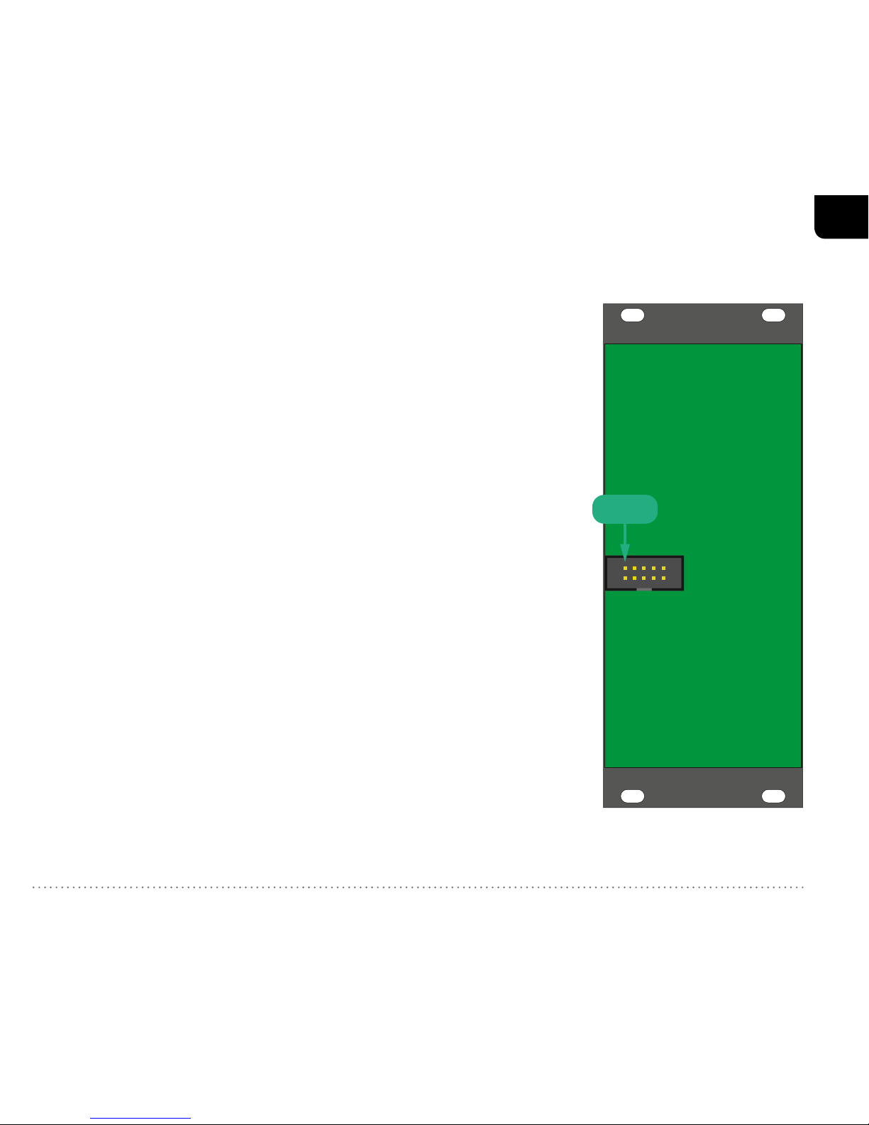
2. Connect the supplied ribbon-cable with its 10-pole connector to the corresponding multi-pin connector on
quadroPOL’s rear.
Page 4
3
EN
⚠
The corresponding plug socket is protected against reverse polarity. Therefore, the 10-pole
connector of the ribbon-cable will only fit in one direction into the module. (See "Figure 1:
quadroPOL rear") The supplied ribbon-cable is colorcoded at the -12 volts position. Note, that this may differ
from other manufacturers. Therefore, only use the
supplied ribbon-cable to connect quadroPOL to your
frame’s system bus!
3. Connect the ribbon-cable’s 16-pole connector to an empty plug-socket
of your frame’s system bus. Make sure the color-coded side of the
cable points towards -12 volts!
⚠
Connecting the ribbon-cable with reverse polarity can
lead to damage of your module or other modules when
powering the system! Double-check the connections
before continuing – safe is safe!
4. Mount quadroPOL to your modular frame using the supplied screws. To
protect the unit’s surface from scratches, use the supplied flat plastic
washers.
5. Reconnect the power cord to your frame and switch on the powersupply. quadroPOL is now ready to operate.
-12 V
Figure 1: quadroPOL rear
Page 5

User Guide quadroPOL
4
Control Elements
quadroPOL offers four identical channels, each with two inputs, one control and one output.
INPUT
A signal applied to this input can be modified by
LEVEL w and a control voltage, being applied to CV
IN r.
LEVEL
LEVEL w adjusts the level for the signal applied to
INPUT q. It works bipolar, meaning, that in its center
position, the applied input signal is suppressed and
the channel is closed. Turning this control to the right
will increase the level. The level also increases when
turning this control to the left, but in this case with
reversed polarity. This function is called polarizer.
LEVEL w has a dead-zone around its center position to
make it easier finding and hitting zero.
In most cases there will be no audible differences
between positive and negative amplitudes when using
complex audio signals. When using sub-audio signals,
i.e. LFO waveforms, the difference will be audible
immediately at its modulation destination:
Figure 2: quadroPOL front
Page 6

5
EN
Where you can hear the positive amplitude of the wave on the in-phase-signal (turning to the right), you will
hear its negative amplitude when using reversed polarity (turning to the left).
With INPUT q not being patched, LEVEL w adjusts an internal generated control voltage. Here, the control also
works bipolar. Turning this control clockwise generates a control voltage of up to +5 volts being provided at the
OUTPUT e connector. Turning the control counterclockwise provides a negative control voltage of up to -5
volts.
OUTPUT
Here, you’ll get the signal out of quadroPOL’s channel.
A jumper on the module’s circuit board selects, whether the channel’s signal will automatically be forwarded to
the following channel when OUTPUT e is not in use (see "Jumper" on page 6).
CV IN
The signal’s level can be modulated with a control voltage, applied to CV IN r. It will be added to the manually
set LEVEL w value. The signal will also be inverted, when the sum of LEVEL w setting and CV IN r voltage is
within a negative voltage range.
Page 7

User Guide quadroPOL
6
Jumper
With the three jumpers on the module’s circuit board you can select whether the output of one channel will
be forwarded and summed up with the following channel (factory setting for all channels). With this feature
activated, quadroPOL can for example be used as mixer (see "Mixer" on page 8).
Figure 3: side view of quadroPOL
Here, channel 2 is forwarded to channel 3 as the jumper is set in channel 3.
Page 8

7
EN
Applications
For a better understanding of quadroPOL’s possibilities, we have collected a few practical examples. These
are meant primarily to serve as suggestions and encourage you to start experimenting with the module. Some
applications are only slight variations or combinations of other examples, but they underline quadroPOL’s
flexibility in use. We are keen to learn how you are using quadroPOL. So don’t hesitate to let us know about your
patch. Send us an email or use the contact form on our homepage.
Attenuator
An external signal is applied to INPUT q and is output at the same channel’s OUTPUT e. By using the
channel’s LEVEL w control, the output level of the signal can be set between zero (center setting for LEVEL w)
and 100% (fully right).
quadroPOL can be used to attenuate control voltages as well as audio signals. It’s an essential function in
modular systems.
Inverter
A signal is applied to INPUT q and output at the same channel’s OUTPUT e. The LEVEL w control of this
channel can vary the signal level between zero (center setting for LEVEL w) and -100% (fully left).
By using this function, control voltages can easily be inverted and adjusted with variable level. Since not all
envelope modules and only a few LFOs offer inverted outputs, quadroPOL may help you out four times.
It also lends itself for the use with audio signals. For Example: Some filters allow to tap the resonance signal and
feed it through an external feedback path. Processing this signal with an inverter, the phase-inverted feedback
leads to sounds not being available with conventional filter modules.
Page 9

User Guide quadroPOL
8
VCA
When being used as a VCA, quadroPOL offers a dynamic range of 80 dB. The type of control is linear.
A signal is applied to the INPUT q and output at the same channel’s OUTPUT e. The corresponding LEVEL w
control remains in its center position, so that there initially is no output signal.
By applying a control voltage to the corresponding CV IN r, the signal level can now be controlled dynamically.
The most common application would be a control using an envelope generator. It is also possible to use a LFO for
tremolo-effects or a step-sequencer for rhythmical control.
Please note that the amplitude will oscillate between the positive and negative range when using a LFO. This
results in an output signal of quadroPOL that rotates between normal (in phase) and inverted (out of phase)
states. To avoid this, you may either need to use a LFO that only provides a positive amplitude output or you
need to apply a sufficient offsets to the LFO-signal. An offset, be it positive or negative, can easily be generated
by setting LEVEL w different to zero.
Mixer
The following examples only work if the jumper(s) on quadroPOL’s circuit board are set (see "Jumper" on page
6).
Beside the use of individual channels, two to four channels may also be combined. To do so, signals have to be
applied at the inputs. The summed-up signal is being tapped at the last of the outputs being used. Other outputs
must not be patched in this case. Use the LEVEL w controls of the channels to adjust the signal levels between 0
(center setting of LEVEL w) and 100% (fully right).
quadroPOL’s channels can be combined at will. The crucial factor is which channel’s OUTPUT e is used as
master output:
Page 10

9
EN
- channel 1 and 2 (OUTPUT e channel w) and/or channel 3 and 4 (OUTPUT e channel r) can be used as
two 2-in-1-mixers.
- channel 1, 2 and 3 (OUTPUT e channel e) can be used as 3-in-1-mixer while channel 4 can be used
individually.
- channel 1 to 4 (OUTPUT e channel r) can be used as 4-in-1-mixer.
Polarizing Mixer
The polarizing application resembles the mixer. The difference is the possible inversion of the signals. New
shapes can be created when mixing for example LFO- or VCO-waveform-signals in- and out-of-phase.
VC-Mixer
By including the channel’s CV INs r, the mixing proportion can be altered dynamically. Thus you can create
lively sounds using CV- or audio-source at the channels’ INPUTs q.
Ring Modulator
In case two continuous signals with consistently changing positive and negative amplitudes (waveforms) are fed
into inputs CV IN r and INPUT q, ring modulation will be applied. Ring modulation will multiply two signals
including their harmonics, creating sums and differences. This can result in pretty complex signals. While the
use of sine waves often leads to results being usable in a musical way, waveforms with stronger harmonic content
usually lead to disharmonic signals. In audio applications, ring modulation is often used to create metallic and
atonal sounds.
The signal being present at the INPUT q connector is the carrier, while the signal fed to the CV IN r input is the
modulator. To achieve mathematical correct results, set LEVEL w to its center position. By moving the control to
Page 11

User Guide quadroPOL
10
the left and right, an offset is added to the signal source which will sonically influence the ring modulation. Feel
free to experiment!
A ring modulator may as well be useful within the sub-audio range. If you feed two simple LFO-signals to the
ring modulator, the result is a more diversified waveform that depends on the frequency ratio between both
signals. This will lead to more lively sounding modulations.
CV-Source
With INPUT q of a channel not being patched, OUTPUT e will provide a static DC-signal which can be
manually adjusted in its intensity using LEVEL w. The voltage covers a range of -5 volts (left) to +5 volts (right).
The control voltage can be used for multiple purposes:
- In case the tuning of a VCO or any other CV-controllable parameter needs to be adjusted more detailed as
being possible from the module itself, quadroPOL’s control voltage can be used to accurately adjust this
function.
- In case a control voltage being generated by quadroPOL is distributed using a multiple module, several
parameters of different modules can be modulated with a single control.
- quadroPOL’s static control voltage is ideally suited to be used as an offset generator which can add fixed
values to specific functions such as transpositions of a sequencer.
- If a control voltage (i.e. a LFO) is applied to CV IN r, an positive or negative offset can be added by turning
LEVEL w to the right or to the left.
Page 12

11
EN
Technical Specications
Levels
optimum input level INPUT ±5 V
optimum input level CV IN ±5 V
generated DC -5 V ... +5 V
Power Consumption
+12 V 45 mA
-12 V 35 mA
+5 V -
Dimensions and Weight
Width / Height 10 HP (129.00 mm) / 3 U
Depth 30.00 mm
Weight 130 g
Page 13

HDB electronic GmbH
Badesteig 20
08258 Markneukirchen
GERMANY
Phone +49 (0) 37422 4027 - 0
Email info@vermona.com
Web www.vermona.com
 Loading...