

Page 1
User Guide
Page 2

Introduction
The analogue drum-synthesizer DRM1 MKIII is not just another instrument or
piece of equipment. It is also part of history - our history.
In its first version, we have reentered the market under the brand name
Vermona with a first product. A return to a market from which we temporarily had to pull back due to significant historical and political changes. This
product was introduced many years ago but the DRM1 is still being produced.
Why? There are still musicians that do not own this product. Actually, we are
surprised by the unbroken demand for the unit. Because of this, the DRM1
has been continuously refined and has reached version MKIII today – the best
drum-synthesizer we have ever created.
Now it is up to you, dear user, customer and musician, to design the best beats
you ever created!
The VERMONA-team
Erlbach/Vogtland
EN
VERMONA DRM1 MKIII - analog drum synthesizer
1
Page 3

Table of Contents
Introduction..........................................................................................................................1
Important Safety Information ...........................................................................................3
Setup ......................................................................................................................................5
Scope of delivery ...........................................................................................................5
Connection and Startup ...............................................................................................5
Setting up audio connections ..............................................................................5
Setting up MIDI connections ................................................................................6
Control elements and connections ..................................................................................7
Front Panel/User Interface .........................................................................................7
Rear Panel .......................................................................................................................8
The Sound Generation ........................................................................................................9
The DRM1 MKIII’s sound channels ......................................................................... 10
KICK ....................................................................................................................... 10
DRUM 1/DRUM 2 ................................................................................................. 12
MULTI ..................................................................................................................... 13
SNARE .................................................................................................................... 15
HI HAT 1/HI HAT 2 ............................................................................................. 17
CLAP ....................................................................................................................... 19
MIDI Functions .................................................................................................................. 20
Setting the MIDI-channel and note numbers ........................................................ 20
Setting the MIDI-channel and note number for an individual DRM-
channel ............................................................................................................ 20
Setting the MIDI-channel and note numbers for all DRM-channels ......... 21
Factory Defaults .................................................................................................. 22
Individual Outputs/Inserts............................................................................................. 23
Use as individual output ........................................................................................... 23
Use as insert ................................................................................................................ 24
Trigger-Inputs (optional) ................................................................................................ 25
Sound Examples................................................................................................................ 26
KICK .............................................................................................................................. 26
DRUM ............................................................................................................................ 26
MULTI ............................................................................................................................ 27
SNARE ........................................................................................................................... 28
HI HAT .......................................................................................................................... 28
CLAP .............................................................................................................................. 29
2
Page 4

Important Safety Information
1. Read these instructions.
2. Keep these instructions. Always include these instructions when passing
the product on to third parties.
3. Heed all warnings.
4. Follow all instructions.
5. Do not use this apparatus near water.
6. Only clean the product when it is not connected to the mains power
supply. Clean only with a dry cloth.
7. Do not block any ventilation openings. Install in accordance with the
manufacturer‘s instructions.
8. Do not install near any heat sources such as radiators, heat registers,
stoves, or other apparatus (including amplifiers) that produce heat.
9. Do not defeat the safety purpose of the polarized or grounding-type plug.
A polarized plug has two blades and a third grounding prong. The wide
blade or the third prong are provided for your safety. If the provided plug
does not fit into your outlet, consult an electrician for replacement of the
obsolete outlet.
10. Protect the power cord from being walked on or pinched, particularly at
plugs, convenience receptacles, and the point where they exit from the
apparatus.
11. Only use attachments/accessories specified by the manufacturer.
12. Use only with the cart, stand, tripod, bracket, or table specified by the
manufacturer, or sold with the apparatus. When a cart is used, use caution
when moving the cart/apparatus combination to avoid injury from tip-over.
13. Unplug this apparatus during lightning storms or when unused for long
periods of time.
14. Refer all servicing to qualified service personnel. Servicing is required when
the apparatus has been damaged in any way, such as power supply cord
or plug is damaged, liquid has been spilled or objects have fallen into the
apparatus, when the apparatus has been exposed to rain or moisture, does
not operate normally, or has been dropped.
15. To completely disconnect this apparatus from the AC mains, disconnect
the power supply cord plug from the AC receptacle.
16. WARNING: To reduce the risk of fire or electric shock, do not expose this
apparatus to rain or moisture.
17. Do not expose this equipment to dripping or splashing and ensure that no
objects filled with liquids, such as vases, are placed on the equipment.
18. The mains plug of the power supply cord shall remain readily accessible.
EN
VERMONA DRM1 MKIII - analog drum synthesizer
3
Page 5

Installation
• Ensure that the room in which you use this product is wired in accordance
with the local electrical code and checked by a qualified inspector.
• Only use this product indoors.
• Do not install the product in hot, humid, or excessively dusty locations, in
direct sunlight or in locations where it is exposed to externally generated
vibrations.
• Do not place burning objects (e.g. candles) on top of or near the product.
• If condensation has formed on the product, e.g. because it was moved from
a cold environment to a warm one, allow the product to acclimatize to
room temperature before using it.
• Do not overload wall outlets and extension cables as this may result in fire
and electric shock.
4
Page 6

Setup
Scope of delivery
To ensure top quality, we carefully inspected the DRM1 MKIII before packaging.
Nevertheless, the module could have been damaged during transportation.
Therefore, we ask you to take a serious look at the unit when unpacking. Do
not hesitate to contact us, should there be anything unusual with the unit or its
packaging.
You should find the following items in the box:
• the DRM1 MKIII
• a power chord
• this manual
• a big portion of fun
Connection and Startup
EN
The DRM1 MKIII is a pure sound module. To make use of it, it needs to be
connected to a sequencer, a computer or keyboard as well as to a mixing desk
or an amplifier. After connecting the module to a power socket using the
supplied power chord, setup the audio- and MIDI-connections as follows:
Setting up audio connections
IMPORTANT CONNECT FIRST, AND THEN SWITCH ON! To protect
your speakers, your audio-interface and, last but not
least, your ears, we urgently recommend setting up all
cable connections while the equipment is switched off.
Do not underestimate level peaks and resulting possible
damage that could occur when plugging in or removing
audio cables.
VERMONA DRM1 MKIII - analog drum synthesizer
5
Page 7
1. The jacks OUT LEFT and OUT RIGHT 9 on the module‘s rear output all
signals in stereo. Connect these jacks to two line-inputs of a mixing desk,
a computer-audio-interface or to an amplifier using two 6.3 mm cables
(TS). Alternatively or in parallel, you may connect a headphone
on the
7
module‘s front panel.
NOTE All of the DRM1 MKIII sound channels offer individual
outputs
, allowing them to be patched to the inputs
5
of a mixing console or an audio-interface. Find more
details in chapter “Individual Outputs/Inserts” on page
23. Use the stereo output as a starting point.
2. Before switching on the unit by pressing its POWER button
, complete
1
all audio connections to avoid loud impulses and cracking noises in your
audio system. These peaks can lead to distortion and could even harm converters when connected directly to an audio-interface. For safety reasons,
while connecting and powering up the unit, turn down the MASTER control
of the DRM1 MKIII as well as the input controls of the units that follow
6
in the signal chain. After powering up the DRM1 MKIII, a corresponding red
LED next to the POWER button
will light up.
1
Setting up MIDI connections
1. The unit that is supposed to control the DRM1 MKIII’s sounds needs to
be connected to the DRM1’s MIDI IN jack
hardware-sequencer, the MIDI output of a software-sequencer (using the
computer’s audio- or MIDI-interface) or a keyboard.
2. MIDI THRU forwards the MIDI data from the DRM1 MKIII’s MIDI input and
allows connecting more MIDI devices.
. This can be a groove box, a
10
6
Page 8
Control elements and connections
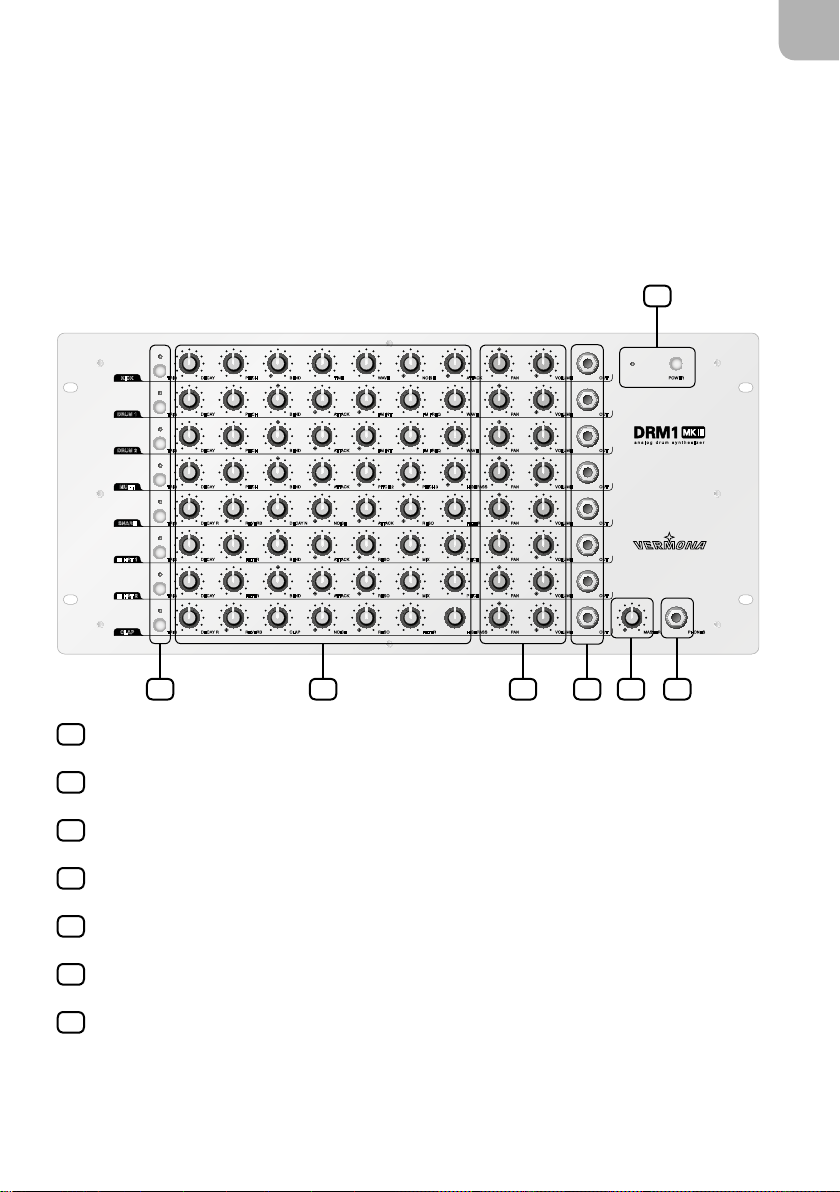
Front Panel/User Interface
EN
1
KICK
DRUM 1
DRUM 2
MULTI
SNARE
HI HAT 1
HI HAT 2
CLAP
DECAY
TRIG
TRIG
DECAY
DECAY
TRIG
TRIG
DECAY
DECAY R
TRIG
DECAY
TRIG
DECAY
TRIG
DECAY R
TRIG
BEND
PITCH
PITCH
BEND
BEND
PITCH
PITCH
BEND
DECAY N
REVERB
FILTER
BEND
FILTER
BEND
REVERB
CLAP FILTER HIGHPASS
WAVE
TIME
FM INT
ATTACK
FM INT
ATTACK
ATTACK
PITCH 2
NOISE
ATTACK
ATTACK
RESO
ATTACK
RESO
NOISE
RESO
NOISE
FM FREQ
FM FREQ
PITCH 3
RESO
MIX
MIX
2 3 4 5 6 7
POWER - power switch with LED
1
TRIG button/LED - triggers sound in channel
2
sound shaping parameters
3
PAN/VOLUME - channel volume and panning
4
OUT - individual outputs/inserts
5
ATTACK
WAVE
WAVE
HIGHPASS
FILTER
PITCH
PITCH
VOLUME
PAN
PAN
VOLUME
VOLUME
PAN
PAN
VOLUME
PAN
VOLUME
PAN
VOLUME
PAN VOLUME
PAN VOLUME
OUT
OUT
OUT
OUT
OUT
OUT
OUT
OUT
POWER
analog drum synthesizer
PHONES
MASTER
MASTER - overall volume
6
PHONES - headphones output
7
VERMONA DRM1 MKIII - analog drum synthesizer
7
Page 9
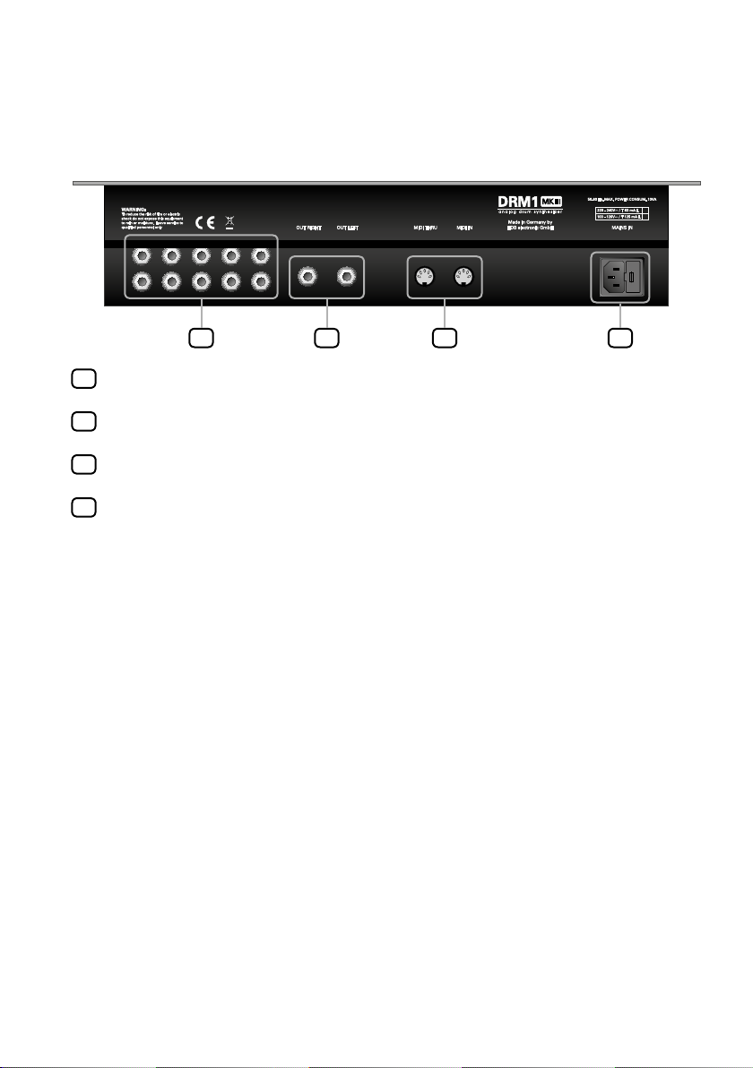
Rear Panel
Use only with a 250V fuse
Employer uniquiment avec
un fusible de 250V
8 9 10 11
Trigger-inputs (optional)
8
Main outputs (OUT RIGHT/OUT LEFT)
9
MIDI-IN/MIDI THRU jacks
10
Power connector and fuse holder
11
8
Page 10

The Sound Generation
Now that you have carefully unpacked and setup the DRM1 MKIII, let’s take
a closer look. Sorry for bothering you with mainly theoretical and security
aspects. To get the most out of this unit in a creative and musical sense, this
was necessary. Now, let’s find out what the DRM1 MKIII really is!
The DRM1 MKIII is a sound module, specialized to create synthetic drum
sounds that are produced by pure analogue circuits. It allows the creation of
eight independent drum- and percussion sounds. Although these sounds carry
the component names of a traditional drum kit, these are “only” imitations of
the real thing. However, this is fully intended. Synthetic or analogue drums
provide an individual character and aesthetic. These sounds have significantly
influenced different musical genres if not made them possible at all. Neither old
school Hip-Hop, Electro, House nor Techno would have been possible without
the aid of the famous analogue drum machines invented by our friends from
Japan.
The DRM1 MKIII has a lot to offer. It covers many aspects of those classic units
but also a lot more. But one thing can certainly be said. The DRM1 MKIII is all
original and not a clone, trying to reproduce 8 or 9 classic sounds.
EN
Let’s take a closer look at the individual drums, consecutively referred to as
channels. At the same time, we will also name possible applications for their
use.
All eight channels in the DRM1 MKIII share three elements:
TRIG This button manually triggers the channel’s sound. Here, the
volume is constant and equals the level at 75% MIDI velocity. Note,
for channels HI HAT 1 and HI HAT 2, these offer an additional
choice of sounds (see “HI HAT 1/HI HAT 2” on page 17).
PAN this control adjusts the channels’ position in the stereo panorama
when using the main- and headphone outputs
audible effect, the channels on the receiving mixing desk need to
be panned to the left and right. Note that PAN is effectless when
using the channels’ individual outputs
VERMONA DRM1 MKIII - analog drum synthesizer
.
5
. To make an
7
9
Page 11

VOLUME this control adjusts the channel’s volume for the main- 9, head-
phone-
and individual outputs 5.
7
The DRM1 MKIII’s sound channels
The eight sound channels are tailored to generate specific drum sounds.
However, thanks to their flexibility, you are explicitly asked to experiment
and get creative. You will find out that each channel offers plenty of different
sounds.
KICK
KICK
DECAY
TRIG
PITCH
BEND
TIME
WAVE
NOISE
ATTACK
PAN
VOLUME
The first channel is optimized to produce bass drum sounds.
DECAY sets the length of the sound until fade out. The first half of the
control allows creating tight kick drums for dance music. From the
noon-setting of the control, the kicks are significantly increasing
in length. These sounds are often found in genres such as Hip-Hop
or R’n’B. With DECAY set to maximum, long sounding bass drums
can be achieved. Use these for Jeep Beats, D’n’B and Dubstep
– BOOOOOOOM
PITCH sets the overall sound frequency. Of course, the lower range of
this knob is relevant when creating bass drums. Start from a 9 o’
clock position. With PITCH adjusted to a higher value, you may as
well create tom- and percussion sounds with this channel. PITCH
interacts with the following parameters BEND and TIME.
BEND adjusts the intensity of a pitch modulation by the TIME envelope.
Higher values will increase the amount of modulation but also
increase the perceived pitch of the sound, especially with DECAY
set to shorter values. Regard PITCH, BEND and TIME as being
interactive.
OUT
10
Page 12

With pitch modulation being completely absent, bass drums may
sound flat and not distinctive; therefore we recommend at least a
little dose of BEND. To create dance-kicks use higher BEND settings
and lower TIME settings. For long booming kicks keep the control
in the lower half.
With PITCH being set to its maximum, BEND can no longer fully
modulate the pitch.
TIME adjusts the release time of the pitch envelope. In general, short
settings are useful for bass drums while longer values will make
the sound lose its kick specific character. A long decay might still
be useful to create percussions and effect sounds.
WAVE is a mix control that seamlessly blends a sinusoid wave form into
a rectangular shape. Here, the sound changes from soft to harder.
Within the first half of the control’s range, the sound receives
additional rawness and depth. At higher values, the sound will
start to overdrive and distort, making an additional pedal possibly
superfluous when wanting to create harder sounding bass drums.
NOISE adds a short fixed noise impulse to the sound’s start. This imitates
the noise of the beater hitting an acoustic bass drum. Always
adjust NOISE in correlation to the complete mix. What might
appear too intrusive when being soloed might already sound too
gentle within a full mix.
EN
ATTACK adds a short fixed needle impulse to the sound’s start. This will
support the bass drum’s assertiveness. Like NOISE, set ATTACK in
correlation to the complete mix. What might appear too intrusive
when being soloed might already sound too gentle within a full
mix. We recommend adding a little ATTACK even to soft bass
drums.
VERMONA DRM1 MKIII - analog drum synthesizer
11
Page 13

DRUM 1/DRUM 2
DRUM 1
TRIG
PITCH
BEND PAN
ATTACK
FM INT
FM FREQ
WAVE
VOLUMEDECAY
OUT
The two DRUM channels are built identically. These are meant to create toms,
percussions and metallic sounds but can also produce bass drums differing in
character to the KICK channel. Thanks to two available channels you may either
create two completely different sounds or create sound pairs such as low and hi
toms or congas.
DECAY sets the release time or the sound’s length. Its range is a little
broader compared to the KICK channel allowing to create very
short clicks.
PITCH sets the channel’s pitch/frequency.
BEND adjusts the amount of a possible pitch modulation by the DECAY
envelope. This control is centered. In its central position, no
modulation is present. Turn clockwise from the center position to
modulate the pitch, descending it. Turn counterclockwise from the
center position will invert the modulation, resulting in ascending
pitch. This modulation interacts with the DECAY setting.
With PITCH being set to its minimum or maximum, BEND can no
longer fully modulate the pitch.
ATTACK adds a short fixed needle impulse to the sound’s start to support
its assertiveness. Always adjust ATTACK in correlation to the
complete mix. What might appear too intrusive when being soloed
might already sound too gentle within a full mix. We recommend
adding a little ATTACK even to soft drum sounds.
FM INT defines the intensity of the frequency modulation, being specified
using FM FREQ. Set fully counterclockwise to switched off FM.
12
Page 14

FM FREQ sets the modulation frequency. Here, the sound is modulated in
pitch using a sine wave. With values starting from the knob’s 9 o’
clock position, the modulation enters the audible range, resulting
in a broad frequency spectrum. This allows creating atonal and
metallic timbres. At lower values, FM will result in modulations
comparable to a typical LFO.
WAVE is a mix control that seamlessly blends a sinusoid wave form into
a rectangular shape. Here, the sound changes from soft to harder.
Within the first half of the control’s range, the sound receives
additional rawness and depth. At higher values, the sound will
start to overdrive and distort. The interaction between WAVE and
the FM parameter will provide a broad sound palette for different
percussion sounds.
MULTI
EN
MULTI
DECAY
PITCH BEND PA N VOLUME
ATTACK
PITCH 2
PITCH 3
HIGHPASS OUTTRIG
The MULTI channel contains three oscillators with broad tuning ranges. Because
of this, the resulting sounds are very flexible, ranging from bass drums and
toms to cowbells and other metallic percussions to sound effects.
DECAY sets the sound’s length.
PITCH defines the pitch of the first oscillator as well as the base pitch for
the other two oscillators.
BEND adjusts the amount of the DECAY envelope on the frequency.
This control is centered. In its central position, no modulation
is present. Turn clockwise from the center position to modulate
the pitch, descending it. Turn counterclockwise from the center
position will invert the modulation, resulting in ascending pitches.
This modulation interacts with the DECAY setting.
With PITCH being set to its minimum or maximum, BEND can no
longer fully modulate the pitches.
VERMONA DRM1 MKIII - analog drum synthesizer
13
Page 15

ATTACK adds a short fixed needle impulse to the sound’s start to support
its assertiveness. Always adjust ATTACK in correlation to the
complete mix. What might appear too intrusive when being soloed
might already sound too gentle within a full mix. We recommend
adding a little ATTACK even to soft drum sounds.
PITCH 2 sets the pitch/frequency of the second oscillator. However, its
base pitch is tied to PITCH. Changing PITCH will always change the
frequency of PITCH 2, too. PITCH 2 can be freely adjusted, so that
it sounds higher or lower than the first oscillator. With PITCH 2 set
fully counterclockwise, the second oscillator is turned off.
PITCH 3 sets the pitch/frequency of the third oscillator. However, its base
pitch is tied to PITCH. Changing PITCH will always change the
frequency of PITCH 3, too. PITCH 3 can be freely adjusted, so that
it sounds higher or lower than the first oscillator. With PITCH 3 set
fully counterclockwise, the third oscillator is turned off.
HIGH PASS adjusts the cutoff frequency of an additional high pass filter. It
allows attenuating bass frequencies of the sound if needed. The
filter’s effect depends upon the sound’s pitch. With PITCH/2/3
being adjusted above the 9 o’ clock position, the high pass filter’s
effect will be almost insignificant.
14
Page 16

SNARE
EN
SNARE
DECAY R
TRIG
REVERB
DECAY N
NOISE ATTACK
RESO
FILTER
PAN VOLUME
OUT
The duty of the SNARE channel is apparent. However, due to its various parameters, the DRM1 MKIII’s snare drum is a lot more changeable than you might
guess from previous analogue drum machines. The sound is build up from
different components: Noise, a needle impulse, a resonance filter and a pseudo
reverb. This allows a wide spectrum of sounds ranging from short “clacks”,
resembling old beat boxes, to compact snare sounds with noise components
and additional reverb.
DECAY REV sets the length of the reverb effect. This parameter’s effect is only
audible with REVERB being enabled. However, even with REVERB
being disabled, this control effects the length of the tonal sound
component with RESO set to the maximum intensity.
REVERB adjusts the intensity of the reverb effect. Note that this is not a
typical reverb but an electronic imitation of the effect. It supports
the vintage sound of the DRM1 MKIII nicely and we prefer it to a
modern more natural sounding reverb. With this control set fully
counterclockwise, the reverb is disabled.
DECAY N sets the release time or length of the sound’s noise component.
This parameter’s effect is only audible with NOISE being enabled.
NOISE sets the volume of the sound’s noise component. By this, the snare
will receive more body and therefore sounds more authentic. With
this control set fully counterclockwise, NOISE is disabled.
ATTACK adds a short fixed needle impulse to the sound’s start to support
its assertiveness on the one hand, but is also used to initiate
oscillation of the resonance filter component. The audibility of
the needle impulse also depends upon the intensity of the filter’s
resonance. Always adjust ATTACK in correlation to the complete
mix. What might appear too intrusive when being soloed might
already sound too gentle within a full mix.
VERMONA DRM1 MKIII - analog drum synthesizer
15
Page 17

RESO specifies the intensity of the filter’s resonance and, as a result,
colors the tonal component of the snare sound. Only at higher
values, the filter will start to self-oscillate. This parameter
interacts with ATTACK, whose needle impulse initiates the filter’s
oscillation.
FILTER sets the cutoff frequency of the low pass filter. Presuming the
filter has been excited to oscillate, this control adjusts the pitch of
the snare’s tonal sound component.
NOTE Different kind of percussion sounds are possible, only
by using the snare drum’s filter section but leaving out
the NOISE component. With FILTER and RESO being
fully opened, the result will sound clave-like. By attenuating RESO, this sound turns into a snare resembling a
preset-beat-box from ‘78. Lowering FILTER and combine
it with different RESO settings, leads to creditable
8-toms, congas and bongos. (see “Sound Examples /
Klangbeispiele” on page 52)
16
Page 18

HI HAT 1/HI HAT 2
DECAY FILTER MIX
HI HAT 1
TRIG
These two channels are meant to create hi-hats but also cymbal sounds. Achieve
a broad spectrum of cymbals, percussions and sound effects on a basis of
filtered noise and a metallic oscillator mixture.
DECAY sets the release time or the sound’s length.
FILTER sets the cutoff frequency of the low pass filter, coloring the overall
sound of the channel.
BEND adjusts the amount of a possible cutoff modulation by the DECAY
envelope. This control is centered. In its central position, no
modulation is present. Turn clockwise from the center position
to modulate the filter’s cutoff frequency, descending it. Turn
counterclockwise from the center position will invert the modulation, resulting in an ascending cutoff frequency. This modulation
interacts with the DECAY setting. The intensity of the BEND effect
is less pronounced as in channels DRUM and MULTI.
BEND PAN VOLUMEATTACK
RESO
PITCH
OUT
EN
ATTACK adds a short fixed needle impulse to the sound’s start to support
the hi-hat and cymbals’ assertiveness. Always adjust ATTACK in
correlation to the complete mix. What might appear too intrusive
when being soloed might already sound too gentle within a full
mix. The pitch of the impulse can be adjusted in parallel with the
oscillator mixture using PITCH.
RESO specifies the intensity of the filter’s resonance which, as a result,
shapes the sound coloration of the hi-hat- and cymbal.
MIX controls the mixture between the noise part and the multiple,
detuned oscillators. Turned fully counterclockwise, only the noise
component will be audible, just as it was used for hi-hats and
cymbals in many old beat boxes. Turned fully clockwise, only the
oscillator mixture will be audible, allowing for more “authentic”
sounds, due to the metallic sound.
VERMONA DRM1 MKIII - analog drum synthesizer
17
Page 19

PITCH defines the pitch/frequency of the oscillator mix as well as for the
ATTACK impulse.
NOTE Both HI HAT channels can be triggered in two versions,
using the TRIG button - either as cymbal/open hi-hat
or as closed hi-hat. The closed hi-hat has a fixed, short
decay time, independent of the DECAY control. After
switching on, the DRM1 MKIII’s TRIG button defaults to
trigger the cymbal/open hi-hat, with the sound’s length
being defined by DECAY. To toggle the trigger-modes,
press and hold TRIG for approx. two seconds. The
TRIG-LED will light up shortly to confirm the operation. By using MIDI, both sounds of these channels,
cymbal/open hi-hat and closed hi-hat, can be played by
different MIDI notes. Here, the dependency between the
two sounds on one channel is automatically reflected
(see “MIDI Functions” on page 20).
18
Page 20

CLAP
EN
CLAP
TRIG
CLAP FILTER HIGHPASS
NOISE
RESO
PAN VOLUMEDECAY R REVERB
OUT
The CLAP channel serves a defined task. It simulates the clapping of several
hands. Like the SNARE channel, CLAP also offers an electronic pseudo-reverb
which, here, is an integral part of the sound and supports its authenticity. The
CLAP channel also incorporates a resonance filter component.
DECAY REV sets the length of the reverb effect. This parameter’s effect is only
audible with REVERB being enabled.
REVERB adjusts the intensity of the reverb effect. Note that this is not a
typical reverb but an electronic imitation of the effect. It supports
the vintage sound of the DRM1 MKIII nicely and we prefer it to a
modern more natural sounding reverb. With this control set fully
counterclockwise, the reverb is disabled.
CLAP sets the speed sequence of the individual claps.
NOISE adjusts the amount of noise that sounds conjointly with the claps.
Without adding any NOISE the results sound unnatural.
RESO specifies the intensity of the filter’s resonance and, as a result,
colors the tonal component of the clap sound in interaction with
the FILTER setting.
FILTER sets the cutoff frequency of the low pass filter. In interaction with
RESO, this control adjusts the coloring of the sound.
HIGH PASS adjusts the cutoff frequency of an additional high pass filter. It
allows attenuating bass frequencies of the sound if needed. The
filter’s effect is quite unobtrusive and more targeted to embed the
clap sound into the DRM1 MKIII’s overall drum kit sound.
VERMONA DRM1 MKIII - analog drum synthesizer
19
Page 21

MIDI Functions
The DRM1 MKIII receives MIDI notes including corresponding velocity data. This
way, the sound can be played dynamically. Other MIDI data such as controller
data are not processed.
Setting the MIDI-channel and note numbers
A small notice to avoid misunderstanding the term “channel”. So far, the
different sounds of the DRM1 MKIII have been simply referred to as “channels”
(calling them instruments or sounds might have been misleading in some
cases). However, in this chapter we refer to “MIDI-channels” that address and
control the “DRM-channels”.
Setting the MIDI-channel and note number for an individual DRM-channel
1. Press the TRIG button of the corresponding DRM-channel while switching
the unit on. Press and hold the button until the sound is triggered.
2. The unit has now entered learn mode.
3. Now, send a MIDI note number to the unit, e.g. by pressing a note on a
connected keyboard. The note number and the MIDI-channel used will be
learned by this DRM-channel.
4. The note number and MIDI-channel are now stored.
Repeat these steps for each DRM-channel if needed. This way you may play the
DRM1 MKIII’s sound on different MIDI-channels.
20
Page 22

Setting the MIDI-channel and note numbers for all DRM-channels
1. Press any two TRIG buttons while switching the unit on. Press and hold the
buttons until both sounds are triggered.
2. The unit has now entered learn mode.
3. Now, send a sequence of eight note numbers to the unit, e.g. by pressing
notes on a connected keyboard. All note numbers and the MIDI-channel
used for transmission will be learned.
The first transmitted note number refers to the first DRM-channel
KICK. The TRIG LED of this channel will shortly light up and the sound
will be triggered. This confirms the saving of the note number for the
KICK-channel. The DRM1 now automatically advances to the second
DRM-channel (DRUM 1), then to DRUM 2 and so on until reaching the
CLAP-channel.
NOTE Both methods allow assigning multiple DRM-channels
to the same MIDI note number. In this scenario the
sounds will be commonly triggered.
EN
NOTE Since both HI HAT channels allow the triggering of two
sounds (open and closed hi-hat), the HI HAT channels
will automatically be assigned to two note numbers.
The note number being sent to the DRM1 MKIII’s HI
HAT channel assigns the open hi-hat/cymbal sound.
The closed hi-hat is automatically assigned to a note
number two semitones (equals two MIDI notes) below
the open hi-hat. Therefore, pay attention to keep that
position unoccupied when assigning note numbers to
other sounds of the unit.
VERMONA DRM1 MKIII - analog drum synthesizer
21
Page 23

4. After all DRM-channels have been assigned to note numbers, the unit
automatically switches to play-mode. The note assignment is permanently
stored until the next assignment is performed.
NOTE While in learn-mode, the DRM1 MKIII restores its
factory defaults when no note numbers are received
before switching the unit off.
Factory Defaults
Channel MIDI note number
KICK 36 (C)
DRUM 1 48 (c)
DRUM 2 41 (F)
MULTI 58 (b)
SNARE 40 (E)
HI HAT 1 closed 49 (cis)
HI HAT 1 open/CYMBAL 51 (dis)
HI HAT 2 closed 42 (FIS)
HI HAT 2 open/CYMBAL 44 (GIS)
CLAP 39 (DIS)
22
Page 24

Individual Outputs/Inserts
Each DRM-channel offers a dedicated individual output/insert with a choice of
possible applications. Crucial to the outputs’ function is the cable being used,
or to be more exact, the pin-assignment of the connector being placed in the
output jack.
Use as individual output
The OUT jack can be used as an individual out in two ways.
1. By using a standard TS-cable, the signal will be automatically excluded
from the main outputs:
EN
2. By using a special cable with a TRS connector on one side and a TS connector on the other, the signal will additionally remain present on the main
output:
Tip and ring of the TRS connector will need to be connected here.
VERMONA DRM1 MKIII - analog drum synthesizer
23
Page 25

Use as insert
The OUT jack can also be used to insert external effect processors into that
channel, such as filters or delays. To do so, use a so-called Y-cable/insert-cable:
• Connect the TRS connector to the channel’s OUT.
• Connect the send connector to the input of the effect processor.
• Connect the return connector (often color-coded in red) to the output of
the effect processor.
24
Page 26

Trigger-Inputs (optional)
You can purchase the DRM1 MKIII either with or without trigger-inputs.
The eight trigger-inputs allow triggering the DRM1 MKIII’s sound from an
analogue sequencer. The unit will accept gate signals between 2 and 12 volts.
Alternatively, the mode of operation can be switched by internal jumpers to the
use of switch-trigger. Note that this requires the unit to be opened which shall
only be performed by a Vermona authorized service technician or expert.
The analogue trigger-inputs do not respond to dynamic trigger signals. In this
scenario, all sounds of the DRM1 MKIII can only sound at a fixed volume.
EN
VERMONA DRM1 MKIII - analog drum synthesizer
25
Page 27

Sound Examples
KICK
KICK
DRUM 1
PITCH
BEND PAN
VOLUMEDECAY
ATTACK
FM INT
FM FREQ
WAVE
OUT
TRIG
DRUM 1
The following illustrations are meant as initial points for different sounds.
Explore the DRM1 MKIII’s sonic possibilities starting from here. These
parameter settings are rough guidelines since analogue circuits always
possess a life of their own. Especially when tuning the MUTLI oscillators or
using frequency modulation, some millimeters may already make significant
difference in sound.
KICK
Hard Dance Kick
DECAY
TRIG
Long Kick
DECAY
TRIG
DRUM
Moving Percussion
TRIG
Space Tom
PITCH
PITCH
PITCH
BEND
BEND
BEND PAN
TIME
TIME
ATTACK
WAVE
WAVE
FM INT
NOISE
NOISE
FM FREQ
ATTACK
ATTACK
WAVE
PAN
PAN
VOLUME
VOLUME
VOLUMEDECAY
OUT
OUT
OUT
26
Page 28

Game Drum
DRUM 1
MULTI
MULTI
MULTI
MULTI
A
TRIG
MULTI
Cowbell
TRIG
DECAY
Lazer Zap
TRIG
DECAY
Metallic Tic
TRIG
DECAY
HP MiniChords
PITCH
PITCH BEND PA N VOLUME
PITCH BEND PA N VOLUME
PITCH BEND PA N VOLUME
BEND PAN
ATTACK
ATTACK
ATTACK
ATTACK
FM INT
PITCH 2
PITCH 2
PITCH 2
FM FREQ
PITCH 3
PITCH 3
PITCH 3
WAVE
HIGHPASS OUT
HIGHPASS OUT
HIGHPASS OUT
VOLUMEDECAY
OUT
TRIG
DECAY
DRM1 MKIII - analog drum synthesizer
PITCH BEND PA N VOLUME
ATTACK
PITCH 2
PITCH 3
HIGHPASS OUT
27
Page 29

SNARE
PAN VOLUME
DECAY R
REVERB
DECAY N
NOISE ATTACK
RESO
FILTER
OUT
TRIG
SNARE
SNARE
SNARE
SNARE
HI HAT 1
HI HAT 1
Compact Snare
Old Scool Snare
DECAY R
TRIG
Tunable Drum
DECAY R
TRIG
Clave
DECAY R
TRIG
HI HAT
Cymbal
DECAY FILTER MIX
TRIG
Shine Hat
REVERB
REVERB
REVERB
DECAY N
DECAY N
DECAY N
BEND PAN VOLUMEATTACK
NOISE ATTACK
NOISE ATTACK
NOISE ATTACK
RESO
RESO
RESO
RESO
FILTER
FILTER
FILTER
PITCH
PAN VOLUME
PAN VOLUME
PAN VOLUME
OUT
OUT
OUT
OUT
28
DECAY FILTER MIX
TRIG
BEND PAN VOLUMEATTACK
RESO
PITCH
OUT
Page 30

CLAP
PAN VOLUMEDECAY R REVERB
NOISE
RESO
CLAP FILTER HIGHPASS
OUT
TRIG
CLAP
CLAP
Full Claps
Hollow Clap
A
TRIG
Short Guiro
CLAP
TRIG
CLAP FILTER HIGHPASS
CLAP FILTER HIGHPASS
NOISE
NOISE
RESO
RESO
PAN VOLUMEDECAY R REVERB
PAN VOLUMEDECAY R REVERB
OUT
OUT
DRM1 MKIII - analog drum synthesizer
29
Page 31

HDB electronic GmbH
Badesteig 20
08265 Erlbach
GERMANY
Fon: +49 (0)37422 4027 0
Email: info@vermona.com
Internet: www.vermona.com
 Loading...