

Page 1
OWNER’S MANUAL
„DRM1 MKII“
analog drum synthesizer
Page 2

Foreword
Thank you for purchasing the DRM1 MKII – analog drum synthesizer.
With the DRM1 MKII you have acquired a very flexible eight-channel drum synthesizer, which gives you the
possibility to create your own sounds and a lot of the classic analog drum sounds, too. Every sound parameter of
the DRM1 MKII has it’s own controller, so it’s easy to use and you’ll always have the best overview over the
settings.
We would like to please you to read this manual carefully for becoming familiar with the
DRM1 MKII, with it’s various possibilities and to avoid wrong handling.
We wish you success and much fun with your DRM1 MKII
The VERMONA team
Table of Contents
Foreword ................................................................................................................................................................ 2
Table of Contents .................................................................................................................................................. 2
General ................................................................................................................................................................... 3
Control Features and Connections...................................................................................................................... 4
Front Panel .......................................................................................................................................................... 4
Rear Panel ........................................................................................................................................................... 4
Getting started ....................................................................................................................................................... 5
Unpacking............................................................................................................................................................ 5
Inventory .............................................................................................................................................................. 5
Connections ......................................................................................................................................................... 5
The Channels of the DRM1 MKII........................................................................................................................... 6
The channels DRUM1, DRUM2, DRUM3 ............................................................................................................ 6
The Channel MULTI............................................................................................................................................. 7
The channel SNARE............................................................................................................................................ 7
The channels CYMBAL1, CYMBAL2 ................................................................................................................... 8
The channel CLAP............................................................................................................................................... 8
Midi Application..................................................................................................................................................... 9
Adjusting the MIDI- notes and channel ................................................................................................................ 9
Individual Outs/Inserts........................................................................................................................................ 10
Use as Individual Output:................................................................................................................................... 10
Use as Insert...................................................................................................................................................... 10
Declaration of conformity ................................................................................................................................... 11
Page 3

General
Important safety information
The following safety precautions must be observed during all phases of operation, service and repair of this equipment. Failure to comply with
these precautions or with specific warnings in this manual violates safety standards of design, manufacture and intended use of this equipment.
The manufacturer assumes no liability for the customer’s failure to comply with these requirements!
Ground and power connection
To prevent the risk of electrical shock, this equipment must be grounded. The factory setting for power is already made for each country (115V
AC, 230V AC). An individual setting is not allowed by virtue of safety reasons. This modification must be done by qualified personal only!
Voltage peak
The units are equipped to manage voltage peaks, which are often generated at live situations. When using the units with unstable voltage, please
make sure that the device is grounded.
Use near explosive goods
The units should not be used near easy flammable or explosive goods.
Dampness
The units should not be used in damp or wet places. Make sure the unit is not in humid atmospheres, because this could cause condensations
within the unit.
WARNING: Risk of electrical shock!
Connections
Do only use cables, plugs and adapters, which do not affect the normal use of the unit.
Cooling System
The unit should not be used near heating or warm or hot fans. When using the unit in a rack or wall system, make sure that the unit has enough
space to let the generated heat dissolve.
Cleaning
Please clean the unit only with a dry duster. Do not use sharp cleaning fluids or water!
Spare parts or modifications
Modification instructions and schematic information should only be used from service departments of our official authorized VERMONA dealers.
To prevent the risk of electrical shock, please do not open or modify the unit yourself. Before opening the unit always disconnect the power
lead/AC Adapter. Opening or modifying the units causes the loss of warranty claims!
Warranty
The manufacturer warrants this product to be free of defects in material and/or workmanship. The manufacturer’s warranty does not apply to
products that have been damaged due to and/or subjected to improper handling by shipping companies (forwarders), negligence, accidents,
improper use or alteration not authorized by the manufacturer.
This warranty is in lieu of an excluded all other warranties, expressed or implied. The manufacturer will not be liable for incidental or consequential
loss or damage whatsoever, whether based upon allegations or negligence, breach of warranty, or otherwise. This disclaimer of incidental or
consequential damages includes, but is not limited to, property damages, loss of profits, loss of time or other losses or inconvenient resulting from
any defect in the material or workmanship of this product or any other connection with the purchase, operation or use of this product.
Technical changes
All changes, which improve the technical features of the units, can be made without subjective noticed by the manufacturer.
- Page 3 -
Page 4
Control Features and Connections
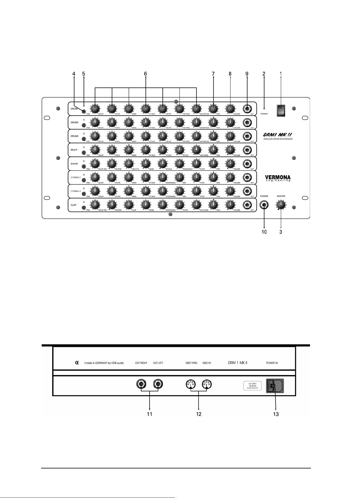
Front Panel
1 POWER switch
2 POWER LED
3 MASTER: Sets the main output level of the DRM1 MKII.
4 TRIG: Button for triggering the sound.
5 TRIG LED: Flashes when the sound will be triggered.
6 Sound programming parameter controls
7 PAN: Places the sound in the stereo field.
8 VOLUME: Individual volume control for each channel.
9 OUT: Individual output/insert jack.
10 PHONES: Jack for connecting a headphone.
Rear Panel
11 OUT RIGHT/OUT LEFT: Master output right and left.
12 MIDI THRU/MIDI IN: MIDI jacks for connecting a MIDI source and for putting the Midi signal through the
DRM1 MKII.
13 POWER IN: Power jack with integrated fuse.
- Page 4 -
Page 5

Getting started
Unpacking
All VERMONA devices are checked and tested carefully before packaging. In spite of special made cartons and
the solid buildup of the devices, damages during the transport are possible. Therefore we would like to please you
to check the unit after receipt for seeable damages.
Please do not discard the original packing! Use it for shipping the unit again, if this is necessary.
Inventory
The VERMONA DRM1 MKII comes complete with:
• The VERMONA DRM1 MK II
• Power cord
• This manual
Please ensure all items above are included. If something is missing contact your local dealer.
Connections
Setting up the necessary audio connections
• Connect the DRM1 MKII with the included power cord to the power socket.
• Connect the outputs of the DRM1 MKII (11) with the line inputs of your mixing console, amplifier, …
(Alternatively, you can use a headphone with the Phones jack (10).)
• Press the POWER switch to turn the device on – the POWER LED (2) flashes.
Note: Before connecting and disconnecting the DRM1 MKII to a power supply source, turn your amp’s volume
control all the way down to avoid damage due to on/off switching noise!
- Page 5 -
Page 6

Setting up the MIDI connections
• Connect the MIDI IN jack (12) with the MIDI OUT jack of your Midi source (i.e. keyboards, sequencer,
computer, …)
• With the MIDI THRU jack you can put the MIDI signal through the DRM1 MKII for controlling other
devices.
The Channels of the DRM1 MKII
In this chapter each channel of the DRM1 MKII will be described shortly, for a better understanding of the
programming parameters.
The parameters PAN and VOLUME as soon as the TRIG button, occurs in every channel. So they were
overlooked in the channel descriptions.
PAN: For placing the sound in the stereo field.
VOLUME: For setting the individual volume for each channel.
TRIG: For triggering the sound with a constant velocity value of 3/4 .
The channels DRUM1, DRUM2, DRUM3
Structure
Each DRUM channel generates a sine, which can be varied in its frequency (PITCH) and decay time
(DECAY).The envelope amount (decay) to the pitch will be set with BEND. The frequency of the sine can also be
modulated by an LFO with a triangle waveform (frequency modulation Æ FM). The highest frequency of the LFO
is around 500Hz. The LFO has an controller for frequency (FM FREQ) and for the modulation intensity (FM
INT.)With the ATTACK control it is possible to add a needle pulse (pulse with very small pulse width). The signal
also can be distorted with the DISTORTION knob.
Control Features
DECAY: Decay time
PITCH: Tone pitch
BEND: Envelope amount to the pitch – middle position = 0
ATTACK: Level of the needle pulse FM INT.: Intensity of the frequency modulation
FM FREQ.: Modulation frequency
DISTORTION: Distortion amount of the signal
- Page 6 -
Page 7

The Channel MULTI
Structure
The MULTI channel has three VCOs, which generate triangle waveforms. The frequencies of the oscillators will
be set with the three pitch controllers. PITCH1 sets the base frequency; PITCH2 and PITCH3 detune the other
two oscillators relatively to PITCH1. If a pitch controller is set to minimum position, the corresponding oscillator is
inactive. DECAY sets the decay time of all oscillators, BEND adjusts the envelope amount to the pitch and
ATTACK adds a needle pulse to the signal. All signals pass a high-pass filter, whose cut-off frequency will be set
with the HIGH PASS controller.
Control Features
DECAY: Decay time of all VCOs
PITCH: Tone pitch for oscillator 1
BEND: Envelope amount to the pitch – middle position = 0
ATTACK: Level of the needle pulse
PITCH2: Tone pitch for oscillator 2; 0 = no second tone
PITCH3: Tone pitch for oscillator 3; 0 = no third tone
HIGH PASS: Cut-off frequency of the high-pass filter
The channel SNARE
Structure
The TRIG button triggers a needle pulse, whose level will be set with ATTACK. According to the setting of the
filter’s cut-off frequency (FILTER) and resonance level (RESONANCE), a damped oscillation will be generated.
With the NOISE controller a noise will be added to the signal. The decay time of the noise will be adjusted with
the DECAY N. controller. (The noise is added after the filter!)A reverb effect will be generated by sending a noise
signal, which can be adjusted with DECAY REV. and REVERB to the filter.
Control Features
DECAY REV.: Decay time – Reverb
REVERB: Reverb amount
DECAY N.: Decay time – Noise
NOISE: Amount Noise
ATTACK: Attack of the needle pulse
RESONANCE: resonance of the low-pass filter
FILTER: Cut-off frequency of the low-pass filter
- Page 7 -
Page 8

The channels CYMBAL1, CYMBAL2
Structure
Each CYMBAL/HI HAT channel has four oscillators with square waveform and a noise generator. The proportion
between noise and the VCOs will be set with the MIX controller. The VCO signals will be filtered independent from
the settings of the controllers and they are tuned in a fixed proportion, the master tune can be set with the PITCH
parameter. The decay time of the oscillators and of the noise will be adjusted via the DECAY controller. There is
also an ATTACK parameter, which adds an impulse. This impulse is taken from one of the four oscillators and
passes an envelope with short decay. The level of the ATTACK impulse is independent of the MIX- and the
DECAY- position.All signals (noise, attack, oscillators) passes the low-pass filter with resonance, whose cut-off
frequency and resonance level will be set with the FILTER and RESONANCE parameter. BEND sets the amount
of the envelope (decay) to the cut-off frequency.
Control Features
DECAY: Decay time
FILTER: cutoff frequency of the low-pass filter
BEND: envelope amount to the pitch – 0 = off
ATTACK: Attack of the needle pulse
RESONANCE: resonance of the low-pass filter
MIX: proportion between noise and oscillators
TRIG Button
The sounds of the CYMBAL channels can be triggered in two different ways – as cymbal/open hat and as closed
hat. The closed hat has a fixed decay time, which is short and independent of the DECAY controller (in this mode
it has no function).Whenever the DRM1 MKII will be switched on, the TRIG button triggers the cymbal/open hat –
sound. For triggering the closed hat, the TRIG button must be pressed for about 2 seconds, the TRIG LED
flashes shortly and the sound will be heard. Now you can trigger the closed hat sound. For triggering the open
hat/cymbal sound, this procedure must be repeated. When controlling the DRM1 MKII via MIDI, every cymbal
channel has two separate note numbers, one for cymbal/open hat and one for closed hat.
The channel CLAP
Structure
The CLAP channel generates five irregular, consecutive needle pulses and noise. With CLAP, the speed of the
impulse sequence will be set. The NOISE parameter adds a noise to the signal. It’s also possible to add an reverb
effect, which is generated in the same way as in the snare channel, but independent of the snare channel. The
DECAY REV. controller is responsible for the decay time of the reverb; the REVERB controller sets the reverb
amount. All signals pass the filter. The FILTER controller sets the cut-off frequency of the low-pass filter and the
RESONANCE controller sets its resonance level. The HIGH PASS controller adjusts the cut-off frequency of the
high-pass filter.
- Page 8 -
Page 9

Control Features
DECAY REV.: Decay time – Reverb
REVERB: Reverb time
CLAP: Speed of the CLAP sequence
NOISE: Amount Noise
RESONANCE: Resonance level of the low-pass filter
FILTER: Cut-off frequency of the low-pass filter
HIGH PASS: Cut-off frequency of the high-pass filter
Midi Application
The DRM1 MKII receives MIDI note and velocity messages (for playing the sounds dynamically).
Adjusting the MIDI- notes and channel
Adjusting a single channel
• Hold down the TRIG button of the channel you like to assign a note number and midi channel, while
switching on the DRM1 MKII. Release the TRIG button, after the specific channel has been triggered.
(TRIG LED flashes)
• The DRM1 MKII is in learn mode now.
• Send the note number and the midi channel to the DRM1 MKII
• The note number and midi channel is stored now.
Adjusting all channels
• Hold down two arbitrary TRIG buttons (4) while switching on the DRM1 MKII. Release the buttons after
these two channels has been triggered.
The DRM1 MKII is in the learn mode, now.
• Send eight note-on messages from your midi source to the DRM1 MKII. (i.e. by pressing eight keys on a
keyboard/synthesizer)
The first note value that will be received from the DRM1 MKII, is valid for the first drum channel (DRUM1).
When the device receives the midi message, the TRIG LED (5) of the corresponding channel flashes and its
sound can be heard.
The note-on value for the first channel is set now and the DRM1 MKII jumps to the next channel (DRUM2).
• This procedure has to be repeated eight times (from DRUM1- up to the CLAP channel).
NOTE: Each cymbal/hi hat channel (CYMBAL1 and CYMBAL2) needs two note numbers, one for cymbal/hi hat
and one for closed hat.
When setting the note-on number for this channels you always assign the value for the cymbal/open hat.
The note-on value for the closed hat will be assigned automatically. It lays two semitones below the open
hat/cymbal, so you have to let a minimum of two semitones space on the keyboard after the previous channel.
(I.e. if you send a B to the Cymbal1 channel, the closed hat is set automatically to an A)
• The midi channel will be sent with the last (8th) midi-note information.
When having sent eight midi-on messages to the DRM1 MKII, it will jump to the normal play mode – the
assignments are stored (also after switching the device off).
- Page 9 -
Page 10

NOTE: If the DRM1 MKII is in the learn mode and doesn’t receive any midi message, the factory settings will be
restored.
It is possible to set more channels of the DRM1 MKII to the same note-on value.
This can be used for special sounds, but it can also be a possible problem source.
Factory Settings:
Channel Midi Note value
DRUM1 36 (C)
DRUM2 48 (c)
DRUM3 41 (F)
MULTI 58 (b)
SNARE 40 (E)
CYMBAL/HI HAT1 closed 49 (cis)
CYMBAL/HI HAT1 open 51 (dis)
CYMBAL/HI HAT2 closed 42 (FIS)
CYMBAL/HI HAT2 open 44 (GIS)
CLAP 39 (DIS)
Individual Outs/Inserts
Each channel of the DRM1 MKII is equipped with a separate output/insert (9), which can be used in different
ways. Deciding for the function of the jack (9) is the used cable type, or rather the plug assignment of the cable.
Use as Individual Output:
The jack (9) can be used as individual out in two different ways:
(1) The signal of the channel that is taken from the individual out will be taken from the main outputs (11).
Therefore you need a simple mono cable:
(2) The signal of the channel that is taken from the individual but is additionally on the main outputs (11).
Therefore you need a special stereo-mono cable:
Tip and Ring of the stereo plug have to be bridged.
Use as Insert
The plug (9) can also be used as channel insert for integrate an external effect unit (i.e. DAF-1, PH-16).
Therefore you need a so-called Y- or Insert-cable:
- Page 10 -
Page 11

Declaration of conformity
for VERMONA DRM1 MKII – analog drum synthesizer
We declare under our sole responsibility that this product is in conformity with the following standards or
standardization documents in attention of operation conditions and installation arrangements acc. to operating
manual:
EN61000-3-2, EN 61000-3-3, EN 55013, EN 55020, EN 60065
according to the provisions of the regulations 89/336/EWG and 73/23/EWG.
HDB electronic GmbH
Badesteig 20
D – 08265 Erlbach
Tel.: +49 (0)3 74 22 – 25 30
Fax: +49 (0)3 74 22 – 23 97
Email: info@vermona.com
http://www.vermona.com
- Page 11 -
 Loading...