

Page 1

Vorwort
Planeten, Galaxien, Mythologien, Philosophien - was musste nicht schon alles zur Namensgebung
von Synthesizern herhalten? Und dann kommt ein Gerät daher, das schlicht und einfach
’14Analogsynthesizer heißt. Was hat es mit dieser, zugegeben, etwas eigenwilligen Namensgebung
auf sich?
Geplant war die Veröffentlichung des ’14Analogsynthesizers bereits für das Jahr 2015. Wir wollten
unser 25-jähriges Firmenbestehen und damit einhergehend 14 Jahre Wiedereinführung der Marke
VERMONA feiern. Als Krönung des Ganzen hatten wir die Idee für ein ganz besonderes Instrument:
Ein einzig nach musikalischen Gesichtspunkten konzipierter Analogsynthesizer, gefertigt nach
höchsten Qualitätsansprüchen. Eben so, wie wir es als Teil des Musikwinkels Deutschlands mit
seiner langen Historie im traditionellen Musikinstrumenten-Handwerk gewöhnt sind. Mit Eifer und
Herzblut machten wir uns an die Verwirklichung des schlicht ’14getauften Projekts.
Bernd Haller, Firmenmitbegründer und Entwickler zahlreicher VERMONA Produkte, verstarb
unerwartet im Februar 2015. Schweren Herzens entschlossen wir, das Synthesizer-Projekt, an
dessen Umsetzung er entscheidend beteiligt war, für unbestimmte Zeit beiseite zu legen.
Mit Verspätung aber nicht ohne Stolz vollendeten wir die Entwicklung des ’14Analogsynthesizers
und stellen das Instrument in unserer kleinen Manufaktur in liebevoller Handarbeit her. Was als
ambitionierter Gedanke begann, verwandelte sich für uns zu einem sehr emotionalen Teil der
neueren VERMONA Geschichte.
DE
Danke, dass Du dich für dieses Instrument entschieden hast. Wir sind uns sicher, dass Du mit ihm
viele kreative und schöne Stunden erleben wirst.
Deine VERMONA Mannschaft aus der
Elektroakustischen Manufaktur, Erlbach
1Bedienungsanleitung ’14 Analogsynthesizer
Page 2

Inhaltsverzeichnis
Vorwort ............................................................................................................................................1
Sicherheitshinweise ..........................................................................................................................4
Einführung .......................................................................................................................................6
Lieferumfang und Auspacken ....................................................................................................6
Inbetriebnahme ..........................................................................................................................7
Aufstellung ..........................................................................................................................7
Herstellen der Audioverbindung ..........................................................................................7
Einschalten ..........................................................................................................................8
Bedienelemente und Anschlüsse ...............................................................................................9
Tonerzeugung ................................................................................................................................ 11
Die Oszillatoren .......................................................................................................................11
Einstellen der Tonhöhe......................................................................................................11
Wellenform und Pulsweite .................................................................................................12
Modulation der Tonhöhe ...................................................................................................13
Oszillator-Synchronisation ................................................................................................14
Glide ..................................................................................................................................14
Der Mixer .................................................................................................................................15
Das Filter .................................................................................................................................. 16
Cutoff, Resonance und Tracking ........................................................................................ 16
Modulation der Cutoff-Frequenz .......................................................................................17
Der Verstärker ..........................................................................................................................18
Modulation und Spielhilfen .....................................................................................................19
Die Hüllkurvengeneratoren ...............................................................................................19
Der LFO .............................................................................................................................. 21
LFO Reset ....................................................................................................................21
LFO Synchronisation ...................................................................................................22
Modulationsrad und Aftertouch ........................................................................................23
Vibrato.........................................................................................................................23
Filter Modulation VCF MOD ........................................................................................ 24
Pitch Bender ......................................................................................................................24
Anschlagdynamik (VELOCITY) .......................................................................................... 25
Lautstärkepedal .................................................................................................................25
Haltepedal (Sustain) ..........................................................................................................25
Arpeggiator und Sequenzer ............................................................................................................26
ARP Modus ............................................................................................................................... 27
Pattern ...............................................................................................................................27
UP ................................................................................................................................28
DOWN .........................................................................................................................28
UP & DOWN ................................................................................................................28
2
Page 3

RANDOM ..................................................................................................................... 28
ALTERNATE ................................................................................................................29
ORDER ......................................................................................................................... 29
Arpeggio Geschwindigkeit .................................................................................................30
Notenlänge ........................................................................................................................30
Sequenzen ................................................................................................................................ 31
Speichern von Arpeggios als Sequenzen ............................................................................ 31
Abspielen von Sequenzen ..................................................................................................31
Arpeggiator über MIDI senden ................................................................................................. 32
Interner Taktgeber und MIDI-Clock ...............................................................................................33
MIDI-Clock aktivieren .............................................................................................................. 33
Den internen Taktgeber als MIDI-CLOCK ausgeben ................................................................34
MIDI Einstellungen ........................................................................................................................35
Einstellen des MIDI-Ein- und Ausgangskanals ........................................................................35
Local Off ................................................................................................................................... 36
Mono Lancet MIDI Parameter mit dem ’14Analogsynthesizer steuern ................................... 37
Analoge CV- und GATE-Ausgänge .................................................................................................38
DE
3Bedienungsanleitung ’14 Analogsynthesizer
Page 4

Sicherheitshinweise
Die folgenden Sicherheitshinweise müssen während des gesamten Betriebs, Services
oder der Reparatur des ’14 Analogsynthesizers beachtet werden. Die Nichtbeachtung der
Sicherheitsvorschriften stellt eine Verletzung des Sicherheitsstandards der Bauweise, Herstellung
und der vorgesehenen Verwendung unserer Geräte dar.
Wir lehnen im Falle einer Verletzung dieser Vorschrift jegliche Haftung ab!
Schutz vor Spannungsspitzen
Der ’14 Analogsynthesizer ist serienmäßig darauf ausgelegt, Spannungsspitzen, wie sie
im alltäglichen Betrieb vorkommen, zu verkraften. Im Falle des Einsatzes des Gerätes bei
ungleichmäßiger Versorgung mit Wechselspannung ist unbedingt auf eine ordnungsgemäße
Erdung zu achten.
Reinigung
Verwende zum Reinigen des ’14 Analogsynthesizers ausschließlich ein weiches, trockenes Tuch
(wie es dem Gerät beiliegt). Verwende keine scharfen Reinigungsmittel oder Wasser!
Betrieb in der Nähe explosionsfähiger Stoffe
Der ’14 Analogsynthesizer darf, wie alle elektrischen Apparate, nicht in der Nähe leicht
entflammbarer oder explosiver Stoffe betrieben werden.
Schutz vor Feuchtigkeit
Der ’14 Analogsynthesizer darf nicht in nasser oder feuchter Umgebung betrieben werden, also
nicht in Räumen mit nassen oder feuchten Böden, Wänden oder Decken. Zu hohe Luftfeuchtigkeit
ist absolut zu vermeiden, da es sonst im Geräteinneren zur Kondensatbildung kommen kann.
ACHTUNG! ELEKTRISCHE SCHLAGGEFAHR!
Zubehör
Verwende keine Kabel, Stecker oder sonstiges, in den normalen Betrieb eingreifendes Zubehör, das
nicht ausdrücklich also solches gekennzeichnet ist.
Lüftung
Der ’14Analogsynthesizer darf nicht in der Nähe oder bei einer Wärmequelle (z. B. Öfen, Heizlüfter,
etc.) verwendet werden. Bei festen Installationen ist für eine entsprechende Lüftung zur Ableitung
entstehender Abwärme zu sorgen.
4
Page 5

Ersatzteile und/oder Modikationen
Wartungsvorschriften und schaltungstechnische Informationen dienen ausschließlich dem
Servicepersonal der hierfür autorisierten Fachhändler. Um die Gefahr eines elektrischen Schlags
zu vermeiden, dürfen keine Service- oder Wartungsarbeiten durchgeführt werden, die nicht
ausdrücklich als solche gekennzeichnet sind.
VOR DEM ÖFFNEN DES GERÄTS IST UNBEDINGT DAS NETZKABEL VOM GERÄT ZU
TRENNEN!
Ersetze keine Bauteile, solange das Netzkabel verbunden ist!
WEGEN VERLETZUNGSGEFAHR IST DER EINBAU ZUSÄTZLICHER TEILE UND JEGLICHE
MODIFIKATION BESTEHENDER SCHALTUNGEN AUSDRÜCKLICH UNTERSAGT!
WIR ERKENNEN IN SOLCHEN FÄLLEN KEINERLEI HAFTUNGSANSPRÜCHE AN!
DE
5Bedienungsanleitung ’14 Analogsynthesizer
Page 6

Einführung
Lieferumfang und Auspacken
Wir haben den ’14 Analogsynthesizer vor dem Versand sorgfältig überprüft und gewissenhaft
verpackt. Leider können wir Beschädigungen während des Transports nicht ausschließen, deshalb
bitten wir dich, das Gerät und die Verpackung nach Erhalt selbst noch einmal gründlich in
Augenschein zu nehmen. Im Falle eines Schadens hilft eine schnelle Mitteilung an uns, das Problem
zu beheben.
Zum Lieferumfang gehören:
- der ’14Analogsynthesizer
- ein stabiles Haltepedal
- ein Netzkabel
- eine passende Staubschutzhülle
- ein Mikrofasertuch
- diese Bedienungsanleitung mit Mappe und Zertifikat
6
Page 7

Inbetriebnahme
Bitte beachte die folgenden Hinweise zur Inbetriebnahme Deines ’14Analogsynthesizers.
Aufstellung
Um Kratzer an Möbelstücken und am ’14Analogsynthesizer zu vermeiden sollte er auf einer ebenen
Oberfläche mit ausreichender Breite und Tiefe aufgestellt werden. Achte darauf, dass alle vier
Gerätefüße und nicht die Schrauben an der Unterseite die Standfläche berühren.
Selbstverständlich kannst Du den ’14Analogsynthesizer auch auf einem geeigneten Keyboardständer
verwenden.
Herstellen der Audioverbindung
Der ’14Analogsynthesizer bietet mehrere Abhörmöglichkeiten:
- Kopfhörer: An der Vorderseite, gleich unterhalb der Handräder befinden sich zwei
Kopfhörerausgänge mit 6,3-mm- bzw. 3,5-mm-Klinkenbuchsen s (siehe "Bedienelemente
und Anschlüsse" auf Seite 9). Sie sind mit dem Symbol H beschriftet und können
gleichzeitig benutzt werden. Die Lautstärke der beiden Kopfhörerausgänge wird gemeinsam
aber unabhängig von den Line-Ausgängen mit dem PHONES Regler in der VCA Sektion r
eingestellt.
DE
- Unsymmetrischer Klinkenausgang: Über die rückseitige, mit UNBALANCED beschriftete
Klinkenbuchse d kannst Du den ’14Analogsynthesizer an einem unsymmetrischen Eingang,
z. B. eines Mischpultes oder der Audioschnittstelle eines Computers etc. anschließen.
- Symmetrischer XLR-Ausgang: An der mit BALANCED beschrifteten, männlichen
XLR-Buchse d kannst Du den ’14 Analogsynthesizer an einem symmetrischen Eingang
anschließen. Dieser Ausgang arbeitet mit einem speziell gefertigten Übertrager, entkoppelt
das Audiosignal galvanisch und ist daher für den Bühneneinsatz prädestiniert. Ganz
nebenbei ist im ’14 Analogsynthesizer also gleich eine hochwertige DI-Box integriert.
Die Lautstärke für die UNBALANCED und BALANCED Ausgänge wird gemeinsam mit dem
VOLUME Regler in der VCA Sektion r eingestellt.
7Bedienungsanleitung ’14 Analogsynthesizer
Page 8

Einschalten
Verbinde das mitgelieferte Netzkabel mit der MAINS IN l Buchse an der Rückseite des
’14 Analogsynthesizers. Das interne Netzteil kann mit Wechselspannungen zwischen 90 und
240 Volt, 50/60 Hz betrieben werden. Eine manuelle Anpassung der Spannung am Gerät ist nicht
notwendig und die Anschaffung von Step-Up- oder Step-Down-Konvertern überflüssig.
Schalte den ’14Analogsynthesizer mit dem POWER Schalter ; an der Geräterückseite ein.
8
Page 9
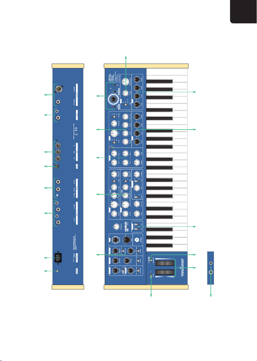
Bedienelemente und Anschlüsse
r
DE
dfghjkl;
tttu i
qy w e a
Abbildung 1:
o
Bedienelemente und Anschlüsse des ’14Analogsynthesizers
s
9Bedienungsanleitung ’14 Analogsynthesizer
Page 10

VCOSektion (siehe "Die Oszillatoren" auf Seite 11)
q
Mixer (siehe "Der Mixer" auf Seite 15)
w
VCF Sektion (siehe "Das Filter" auf Seite 16)
e
VCA Sektion (siehe "Der Verstärker" auf Seite 18)
r
Hüllkurven (siehe "Die Hüllkurvengeneratoren" auf Seite 19)
t
Modulations-Sektion und u Handräder (siehe "Modulationsrad und Aftertouch" auf Seite 23
y
und siehe "Pitch Bender" auf Seite 24)
ARPEGGIATOR Schalter (siehe "Arpeggiator und Sequenzer" auf Seite 26)
i
Oktav-Schalter
o
Programmer
a
Kopfhörerausgänge und d Hauptausgänge (siehe "Inbetriebnahme" auf Seite 7)
s
Audio-Eingänge (siehe "Der Mixer" auf Seite 15)
f
MIDI Buchsen (siehe "MIDI Einstellungen" auf Seite 35)
g
USB-Buchse für Firmwareupdates
h
Haltepedal- und Fußschweller-Eingang (siehe "Haltepedal (Sustain)" auf Seite 25 bzw. siehe
j
"Lautstärkepedal" auf Seite 25)
CV- und Gate Ausgänge (siehe "Analoge CV- und GATE-Ausgänge" auf Seite 38)
k
Netzbuchse und ; Netzschalter (siehe "Inbetriebnahme" auf Seite 7)
l
10
Page 11

Tonerzeugung
In diesem Abschnitt erklären wir die Funktionen und Bedienelemente der Tonerzeugung. Wir
setzen voraus, dass Du mit den Grundlagen der Spannungssteuerung und subtraktiven Synthese
vertraut bist.
Der ’14Analogsynthesizer folgt der klassischen VCO-VCF-VCA-Struktur: Die spannungsgesteuerten
Oszillatoren (VCOs) erzeugen den Ton, ein spannungsgesteuertes Filter (VCF) formt dessen Klang
und der spannungsgesteuerte Verstärker (VCA) steuert den Lautstärkeverlauf. Hinzu kommen
zahlreiche Modulatoren und Spielhilfen.
Die Oszillatoren
Die beiden Oszillatoren VCO 1 und VCO 2 erzeugen Wellenformen mit unterschiedlicher
Obertonstruktur. Sie liefern das Rohmaterial und geben die grundsätzliche Färbung des Klangs vor.
VCO1 und VCO2 sind gleichwertig und verfügen, bis auf einige zusätzliche Merkmale von VCO2,
über den gleichen Funktionsumfang. Wir beschreiben identische Bedienelemente und Funktionen
deshalb für VCO1 und VCO2 gemeinsam.
DE
Einstellen der Tonhöhe
Mit den drei Bedienelementen OCTAVE, COARSE und FINE kann der große Tonumfang der
Oszillatoren präzise kontrolliert werden.
Der OCTAVE Schalter bestimmt die Oktavlage. Zur Auswahl stehen 16’, 8’, 4’ und FIX.
In den Positionen 16’, 8’ und 4’ regelt COARSE die Tonhöhe stufenlos in einem Bereich von plus/
minus einer Oktave. Statt einer Mittenrastung hat der Regler um die 12-Uhr-Position einen „toten
Bereich“. Das Auffinden der Nullstellung gelingt damit zuverlässig, auch ohne Hinsehen, während
sich minimale Verstimmungen präzise einstellen lassen.
Feinste Schwebungen und Korrekturen können mit dem FINE Regler mit einem Regelbereich von
plus/minus einem Halbtonschritt eingestellt werden.
In der Position FIX des OCTAVE Schalters wird der Oszillator von der Tastatur entkoppelt. COARSE
regelt nun den gesamten Tonumfang.
11Bedienungsanleitung ’14 Analogsynthesizer
Page 12

Die Gesamtstimmung des ’14Analogsynthesizers wird mit dem MASTER TUNE Regler in einem
Bereich von insgesamt einem Halbtonschritt eingestellt. Der darunter liegende Taster erzeugt einen
Referenzton von 440 Hz (Kammerton A).
Zu jedem Oszillator gehört ein Suboszillator, der eine Oktave unterhalb der eingestellten Tonhöhe
schwingt.
Wellenform und Pulsweite
Der WAVE Schalter bestimmt die Wellenform des Oszillators. Zur Auswahl stehen Sinus (5),
Sägezahn (1) und Rechteck (3).
PULSEWIDTH regelt die Pulsweite der Rechteck-Wellenform. Bei Linksanschlag beträgt sie 50
Prozent. In dieser Position erzeugt der Oszillator ein symmetrisches Rechteck. Bei Rechtsanschlag
des Reglers beträgt die Pulsweite 95 Prozent.
Die Pulsweite kann zusätzlich vom LFO moduliert werden. Die Intensität der Modulation wird für
VCO1 und VCO2 gemeinsam mit dem LFO PWM INT Regler eingestellt.
H Durch die Pulsweitenmodulation kann die maximale Pulsweite über die manuell
einstellbaren 95% hinaus moduliert werden. Ab einer Pulsweite von 100% ist
der Oszillator nicht mehr hörbar. Durch dieses Verhalten können interessante
rhythmische Effekte erzeugt werden, wenn die LFO Wellenform etwa auf Rechteck
oder Zufall steht.
Die Wellenformen der beiden Suboszillatoren sind vorgegeben. Der Suboszillator von VCO1 erzeugt
einen Sinus, der von VCO2 ein Rechteck. PULSEWIDTH und LFO PWM INT haben keinen Einfluss
auf die Suboszillatoren.
12
Page 13

Modulation der Tonhöhe
Zur Modulation der Tonhöhe stehen der Hüllkurvengenerator EG 1 und für VCO2 zusätzlich der
LFO und die Sinus-Wellenform von VCO1 zur Verfügung.
H Weitere Möglichkeiten zur Tonhöhenmodulation durch den Vibrato Generator
und Pitch Bender erläutern wir in den Abschnitten "Vibrato" auf Seite 23 und
"Pitch Bender" auf Seite 24.
EG 1 INT regelt die Intensität der Tonhöhenmodulation durch den Hüllkurvengenerator EG1. Der
Regler rastet in der 12-Uhr-Position ein - hier findet keine Modulation statt. Durch Drehen nach
Links wird die Tonhöhe negativ, also nach unten moduliert; durch Drehen nach rechts wird sie
positiv, also nach oben moduliert.
Die Tonhöhe von VCO2 kann zusätzlich vom LFO moduliert werden. Die Intensität wird mit dem
LFO INT Regler eingestellt.
Als weitere Modulationsquelle für VCO2 dient die Sinus-Wellenform von VCO1. VCO 1 i INT
bestimmt die Intensität dieser sogenannten Cross-Modulation.
H Cross-Modulation eignet sich bei niedriger Intensität zum leichten Verzerren des
Klangs. Bei starken Intensitäten entstehen harte Klänge, die sich allerdings nicht
mehr über den vollen Tonumfang der Oszillatoren spielen lassen. In Verbindung
mit der Oszillator-Synchronisation lassen sich jedoch gut spielbare, metallisch
harte Lead- und Bass-Sounds realisieren.
DE
DieTonhöhedesmodulierendenOszillators(VCO1)beeinflusstdasErgebnisder
Cross-Modulation genauso wie deren Intensität mittels VCO 1 i INT selbst.
13Bedienungsanleitung ’14 Analogsynthesizer
Page 14
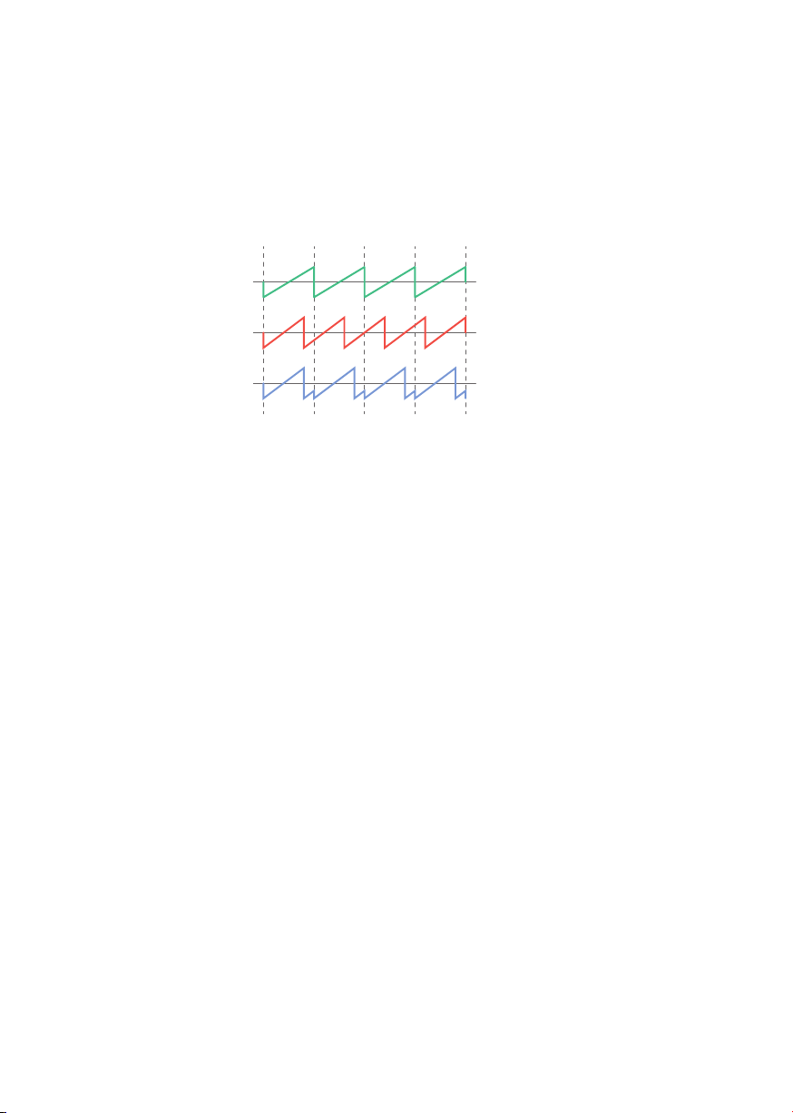
Oszillator-Synchronisation
Die Sync-Funktion der Oszillatoren bietet sich für harte Klänge an. Bei der Synchronisation wird die
Wellenform des Slave-Oszillators nach jedem vollen Wellenform-Durchlauf des Master-Oszillators
neu gestartet. Dem Slave wird also die Tonhöhe des Masters aufgezwungen und damit dessen
Wellenform verändert.
VCO 1 (Master)
VCO 2 (Slave)
VCO 2 SYNC ON
Abbildung 2:
Veränderung der Wellenform von VCO2 bei aktiviertem Sync
Beim ’14Analogsynthesizer ist VCO1 der Master und VCO2 der Slave. Der SYNC 1->2 Schalter
aktiviert die Oszillator-Synchronisation.
H Bei "klassischen" Sync-Sounds sollte die Tonhöhe des Slave-Oszillators, beim
’14 Analogsynthesizer also die von VCO 2, höher als die des Masters und
als Wellenform Rechteck ausgewählt sein. Durch die Modulation des Slave-
Oszillators (VCO 2) durch EG 1und/oderdem LFO wird der Obertongehalt der
Wellenform dynamisch verändert.
Glide
GLIDE regelt die Zeit, die für den Tonwechsel zwischen zwei gespielten Noten benötigt wird. Bei
Linksanschlag erfolgt der Tonwechsel abrupt. Je weiter der Regler aufgedreht wird, desto länger die
Zeit, die bis zum Erreichen der neuen Tonhöhe vergeht - der Ton gleitet zum nächsten.
Bei aktivem LEGATO Schalter wirkt der Effekt nur bei gebunden gespielten Noten.
14
Page 15
Der Mixer
Mit den Lautstärke-Reglern des Mixers wird das Mischungsverhältnis der einzelnen Signalquellen
zueinander eingestellt. Die Funktionsweise der Regler ist selbsterklärend: Je weiter ein Regler
aufgedreht wird, desto lauter ist das entsprechende Signal; bei Linksanschlag wird es komplett
ausgeblendet.
VCO 1, VCO 2, SUB 5 und SUB 3 regeln die Pegel der Oszillatoren und ihrer Suboszillatoren.
NOISE regelt die Lautstärke des Rauschgenerators (weißes Rauschen).
EXTERNAL regelt die Lautstärke eines, über die beiden rückseitigen INPUT Buchsen f zugeführten,
externen Signals.
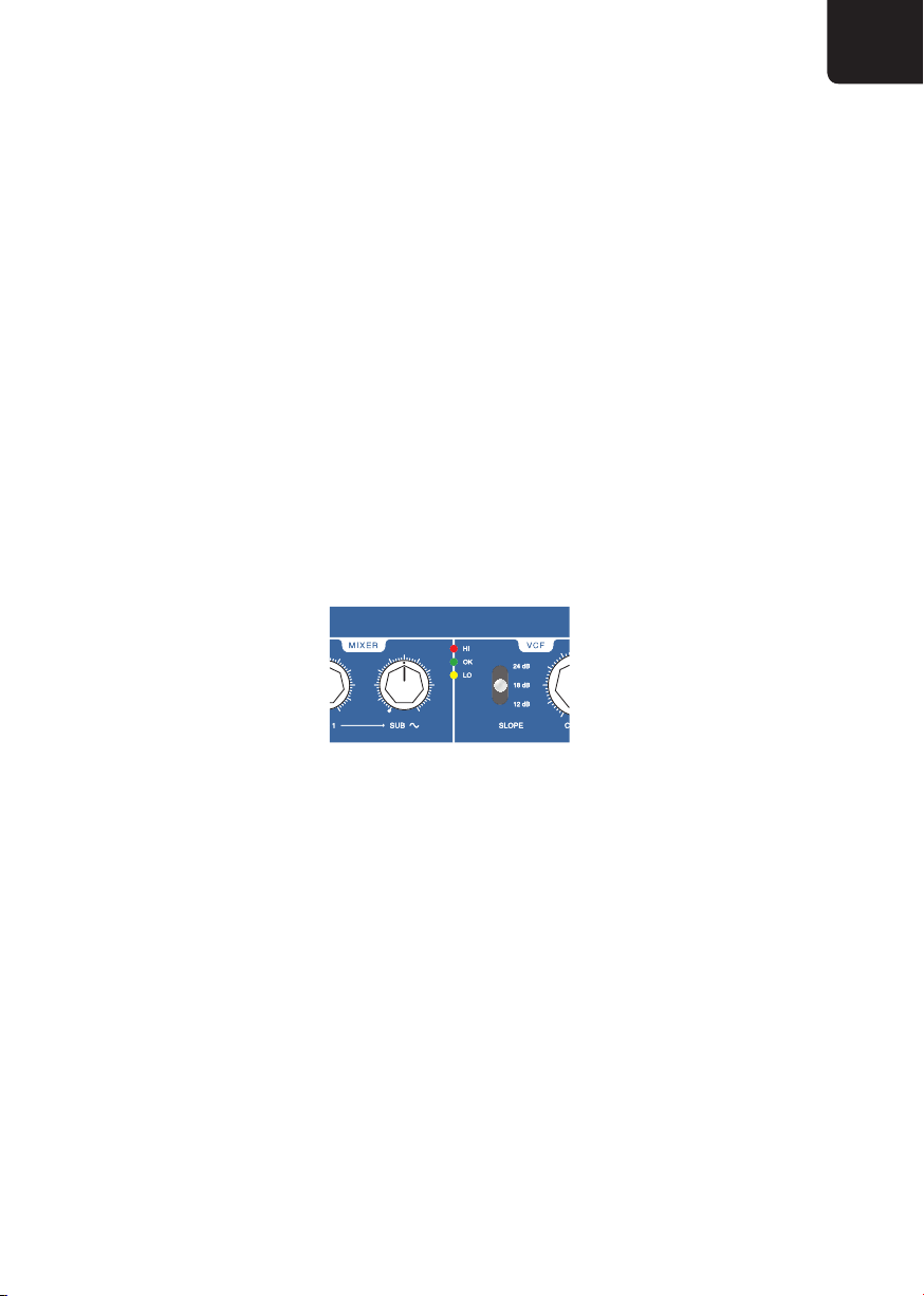
Der Ausgangspegel des Mixers hat einen enormen Einfluss auf den Klangcharakter des Filters. Aus
diesem Grund haben wir dem ’14Analogsynthesizer eine Pegelanzeige, bestehend aus drei LEDs mit
den Farben gelb, grün und rot spendiert. Sie zeigen, von unten nach oben, die folgenden Zustände
an:
DE
Abbildung 3: Die Pegelanzeige des Mixers
- LO (gelb) - Der Ausgangspegel des Mixers ist zu niedrig. Damit verschlechtert sich das
Rauschverhalten des gesamten Instruments. Leuchtet die gelbe LED, sollten die gewünschten
Lautstärkeregler weiter aufgedreht werden.
- OK (grün) - Der Ausgangspegel des Mixers ist technisch betrachtet optimal und das Filter hat
genügend Reserven für starke Rückkopplungen. D.h. der RESONANCE Regler arbeitet sehr
feinfühlig und großzügig. Das Filter hat einen sauberen Klang.
- HI (rot) - Der Ausgangspegel des Mixers übersteuert den Filtereingang. Die Rückkopplung
kann sich nicht mehr so stark entfalten. Das Filter klingt rau und aggressiv.
15Bedienungsanleitung ’14 Analogsynthesizer
Page 16

Das Filter
Neben den Oszillatoren hat das Filter den größten Einfluss auf den Klang eines Synthesizers.
Entsprechend große Aufmerksamkeit haben wir auf seine Ausstattung und Musikalität gelegt.
Im ’14 Analogsynthesizer verrichtet ein resonanzfähiges Tiefpassfilter mit wählbarer
Flankensteilheit seinen Dienst. Es kann über einen weiten Bereich gestimmt gespielt und damit als
zusätzliche Klangquelle eingesetzt werden.
Cutoff, Resonance und Tracking
Der wichtigste Parameter des Filters ist CUTOFF. Beim Tiefpassfilter bestimmt es jene Frequenz
ab der das Signal nach oben hin im Frequenzspektrum beschnitten wird. Je niedriger der CUTOFF
Regler und damit die Cutoff-Frequenz eingestellt ist, desto dumpfer der Klang.
Der SLOPE Schalter bestimmt die Steilheit des Filters, also wie stark die Dämpfung ab der CutoffFrequenz wirkt. Zur Auswahl stehen 12 dB, 18 dB und 24 dB pro Oktave. Bei geringeren Werten
arbeitet das Filter weniger intensiv und weicher im Vergleich zu hohen Werten, bei denen das Filter
straff und kräftig zupackt.
RESONANCE regelt die Stärke der Rückkopplung des Filterausgangs in den Eingang. Je nach Stärke
dieser Rückkopplung entsteht eine mehr oder weniger markante Betonung des Bereichs um die
Cutoff-Frequenz.
Bei hohen RESONANCE Einstellungen beginnt das Filter zu schwingen und erzeugt selbst einen
Ton (Eigenresonanz), dessen Tonhöhe mit CUTOFF bestimmt wird.
H Die Wirkung von RESONANCE ist stark vom Ausgangspegel des Mixers abhängig
siehe "Der Mixer" auf Seite 15.
Der TRACKING Schalter bestimmt die Einflussnahme der Klaviatur auf die Cutoff-Frequenz. In
der OFF-Position bleibt die mittels CUTOFF eingestellte Frequenz unbeeinflusst. Bei FULL folgt
die Cutoff-Frequenz der, auf der Klaviatur gespielten Tonhöhe. In dieser Position kann die, durch
Eigenresonanz erzeugte Schwingung des Filters, in einem Bereich von ca. dreieinhalb Oktaven
gestimmt gespielt werden. In der HALF-Position ist die Einflussnahme der Tonhöhe nur noch bei
50%.
H TRACKING erlaubt es tief gefilterte, dumpfe Klänge über den vollen Tonumfang
des ’14 Analogsynthesizers zu spielen, ohne dass der Ton in höheren Lagen
ausdünnt oder gar unhörbar wird.
16
Page 17

Modulation der Cutoff-Frequenz
Zur Modulation der Cutoff-Frequenz stehen der Hüllkurvengenerator EG1, der LFO und die SinusWellenform von VCO1 zur Verfügung.
H Weitere Möglichkeiten zur Modulation der Cutoff-Frequenz mittels
Modulationsrad und Aftertouch erläutern wir im Abschnitt "Filter Modulation
VCF MOD" auf Seite 24.
EG 1 INT regelt die Intensität der Cutoff-Modulation durch den Hüllkurvengenerator EG1. Der
Regler rastet in der 12-Uhr-Position ein - hier findet keine Modulation statt. Durch Drehen nach
links wird die Cutoff-Frequenz negativ, also nach unten moduliert; durch Drehen nach rechts wird
sie positiv, also nach oben moduliert.
LFO INT regelt die Intensität der Modulation durch den LFO.
Sehr drastische Effekte entstehen durch die Modulation der Cutoff-Frequenz durch die SinusWellenform von VCO 1. Die Intensität dieser Frequenzmodulation (kurz FM) kann manuell
eingestellt und durch den Hüllkurvengenerator EG1 dynamisch verändert werden.
VCO 1 i INT regelt die Intensität der FM manuell. Der dazugehörige EG 1 INT Regler bestimmt
die Intensität der FM durch den Hüllkurvengenerator EG1. Der Regler rastet in der 12-Uhr-Position
ein - hier hat EG1 keinen Einfluss auf die FM-Intensität. Durch Drehen nach Links wird die, mittels
VCO 1 i INT manuell eingestellte FM verringert, durch Drehen nach Rechts erhöht.
DE
H Steht VCO 1 i INT auf Linksanschlag (Null) hat eine Verringerung der FM-
IntensitätdurchEG1(EG1 INTaufLinksanschlag)keineWirkung.
Neben der Tonhöhe von VCO1 und der Cutoff-Frequenz haben RESONANCE- und TRACKING-
Einstellungen großen Einfluss auf das Ergebnis der FM.
17Bedienungsanleitung ’14 Analogsynthesizer
Page 18

Der Verstärker
Das letzte Glied in der Kette der Klangerzeugung ist der spannungsgesteuerte Verstärker (VCA).
Hier wird die Lautstärke manuell festgelegt und durch den Hüllkurvengenerator EG2 dynamisch
gestaltet.
Der MODE Schalter bestimmt die generelle Betriebsart des VCAs. In der Position ON ist er
permanent eingeschaltet.
In den Positionen EG2 und EG2+LFO wird die dynamische Steuerung durch den Hüllkurvengenerator
EG2 bzw. dessen zusätzliche Beeinflussung durch den LFO während dessen Sustain-Phase aktiviert
(siehe "Die Hüllkurvengeneratoren" auf Seite 19).
MASTER VOLUME regelt die Lautstärke für die beiden Hauptausgänge d auf der Rückseite des
’14Analogsynthesizers.
PHONES regelt die Lautstärke für die beiden Kopfhörerausgänge s unterhalb der Handräder.
18
Page 19

Modulation und Spielhilfen
Wie in den Abschnitten zuvor beschrieben, gibt es im ’14Analogsynthesizer mehrere Möglichkeiten,
um die Tonhöhe der Oszillatoren oder die Cutoff-Frequenz des Filters automatisiert zu modulieren.
Allen voran die beiden Hüllkurvengeneratoren EG1 und EG2, der LFO und Vibrato-Generator.
Die Handräder, sowie Anschlagdynamik und Aftertouch der Klaviatur sind weitere
Modulationsquellen, mit denen Du den Klang individuell formen und Deinem Spiel eine eigene
Note verleihen kannst.
Die Parameter der Modulatoren sind direkt über die Regler und Schalter auf der linken Seite des
’14Analogsynthesizers y erreichbar. Einige wenige Funktionen werden über die EDIT Parameter
eingestellt.
Die Hüllkurvengeneratoren
Der ’14 Analogsynthesizer hat zwei Hüllkurvengeneratoren (engl. envelope generator - EG),
EG1 und EG2. Während EG2 fest dem VCA zugeordnet ist, kann EG1 mehrere Ziele gleichzeitig
modulieren:
- unabhängig voneinander die Tonhöhen von VCO1 und VCO2
- die Cutoff-Frequenz des Filters
- die Modulationsintensität der Cutoff-Frequenz durch die Sinus-Wellenform von VCO1
DE
Beide Hüllkurvengeneratoren verfügen bis auf eine Ausnahme über den gleichen Funktionsumfang.
Wir beschreiben identische Bedienelemente und Funktionen deshalb für EG1 und EG2 gemeinsam.
EG1 und EG2 erzeugen Spannungsverläufe, deren Dauer und Form mit den Parametern ATTACK,
DECAY, SUSTAIN und RELEASE eingestellt werden.
Die Hüllkurvengeneratoren werden durch Betätigen einer Taste der Klaviatur gestartet.
ATTACK regelt die Anstiegszeit bis zum maximalen Pegel der Hüllkurve.
DECAY regelt die Abfallzeit vom maximalen Pegel auf den mit SUSTAIN eingestellten Haltepegel.
Solange die Taste der Klaviatur gehalten wird, bleibt auch der Haltepegel stehen.
RELEASE bestimmt die Abklingzeit nach Freigabe der Klaviatur.
19Bedienungsanleitung ’14 Analogsynthesizer
Page 20
Pegel
SUSTAIN
Zeit
Abbildung 4:
ATTAC K DECAY
Taste gedrückt
RELEASE
Spannungsverlauf der ADSR-Hüllkurvengeneratoren
H Steht der SUSTAIN Regler auf Maximum hat DECAY keine Wirkung. RELEASE
hat wiederum keine Wirkung, wenn der SUSTAIN Regler auf Linksanschlag steht
und die Hüllkurve während der DECAY Phase bereits auf Null gefallen ist.
Alle zeitrelevanten Regler, also ATTACK, DECAY und RELEASE, haben bei
Linksanschlag eine Zeit von einer Millisekunde. Damit ändern sich die Pegel
schlagartig ohne hörbare Verzögerung.
EG1 und EG2 verfügen über eigene Legato-Schalter (unterhalb des MASTER TUNE Reglers). In
ihrer OFF-Position wird die jeweilige Hüllkurve ausnahmslos mit jedem Anschlag einer Keyboard-
Taste neu gestartet. Mit eingeschalteter Legato-Funktion wird die Hüllkurve nur dann neu gestartet,
wenn die Taste der Klaviatur zuvor wieder freigegeben wurde. Bei gebunden gespielten Noten wird
der Verlauf der Hüllkurve hingegen nicht durch deren Neustart unterbrochen.
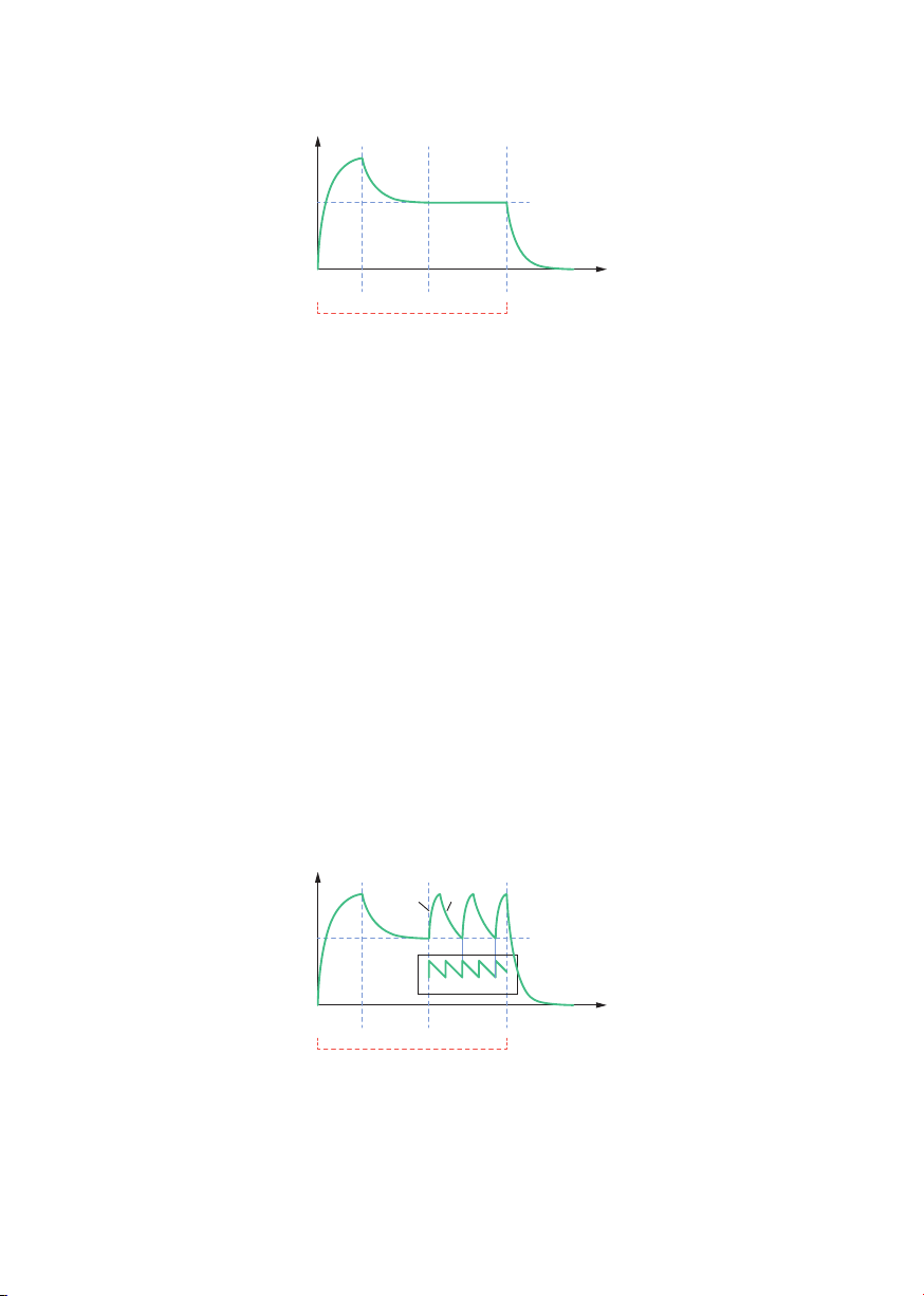
Steht der MODE Schalter des VCAs in der Stellung EG2+LFO, wird die Hüllkurve während ihrer
Haltephase vom LFO getriggert. D. h. Solange eine Taste der Klaviatur gehalten wird, werden Attack
und Decay, nach Ablauf, neu gestartet.
Pegel
20
Abbildung 5:
A D
SUSTAIN
ATTAC K DECAY
Taste gedrückt
LFO
RELEASE
Zeit
Spannungsverlauf von EG2 mit LFO-Retrigger während der Sustain-Phase
Page 21

Der LFO
Der LFO erzeugt niederfrequente Schwingungen. Er kann auf die folgenden Ziele wirken:
- Pulsweite von VCO1 und VCO2 (siehe "Wellenform und Pulsweite" auf Seite 12)
- Tonhöhe von VCO2 (siehe "Modulation der Tonhöhe" auf Seite 13)
- Cutoff-Frequenz des Filters (siehe "Modulation der Cutoff-Frequenz" auf Seite 17).
- VCA in Kombination mit EG 2 (siehe "Der Verstärker" auf Seite 18 bzw. siehe "Die
Hüllkurvengeneratoren" auf Seite 19).
FREQUENCY regelt die Geschwindigkeit (Frequenz) des LFOs in einem Bereich von 0,05 Hz (= 20
Sekunden) bis 100 Hz.
Der WAVE Schalter bestimmt die Wellenform. Zur Verfügung stehen steigender und fallender
Sägezahn (1 / 2), Rechteck (3), Dreieck (4), Sinus (5) und Zufall (RND).
LFO-Reset und -Synchronisation können über die EDIT Parameter eingestellt werden.
LFO Reset
Bei aktiviertem EDIT Parameter [8] LFO RESET wird die Wellenform mit jedem Tastenanschlag der
Klaviatur auf Null gesetzt und der LFO neu gestartet. Führe dazu die folgenden Schritte aus:
1. Stelle sicher, dass sich der ’14Analogsynthesizer im normalen Spielbetrieb befindet
(ARPEGGIATOR Schalter i in Position OFF).
DE
2. Betätige den [EDIT] Taster - die dazugehörige LED leuchtet.
3. Wähle mit dem Auswahlrad EDIT Parameter [8] LFO RESET aus.
4. Durch Betätigen des VALUE Tasters wird der LFO Reset aktiviert (die VALUE LED leuchtet)
oder deaktiviert (die VALUE LED leuchtet nicht).
5. Verlasse den EDIT Modus durch erneutes Betätigen des [EDIT] Tasters.
21Bedienungsanleitung ’14 Analogsynthesizer
Page 22

LFO Synchronisation
Bei aktiviertem EDIT Parameter [9] LFO CLOCK SYNC wird die Geschwindigkeit des LFOs zum
internen Taktgeber oder einer externen MIDI Clock synchronisiert. Der FREQUENCY Regler
bestimmt in diesem Fall ein Teil- oder Multiplikations-Verhältnis. Es gilt die äußere Markierung
um den Regler. Die acht Aufteilungen entsprechen den folgenden Werten:
Abbildung 6:
Vierteltriole
Viertelnote
halbe Note
ganze Note
Teil- und Multiplikations-Verhältnisse bei aktivierter LFO-Synchronisation
Achtelnote
Achteltriole
1/16 Note
1/32 Note
Führe folgende Schritte aus, um die LFO Synchronisation zu aktivieren/deaktivieren:
1. Stelle sicher, dass sich der ’14Analogsynthesizer im normalen Spielbetrieb befindet
(ARPEGGIATOR Schalter i in Position OFF).
2. Betätige den [EDIT] Taster - die dazugehörige LED leuchtet.
3. Wähle mit dem Auswahlrad EDIT Parameter [9] LFO CLOCK SYNC aus.
4. Durch Betätigen des VALUE Tasters wird die LFO Synchronisation aktiviert (die VALUE LED
leuchtet) oder deaktiviert (die VALUE LED leuchtet nicht).
5. Verlasse den EDIT Modus durch erneutes Betätigen des [EDIT] Tasters.
H Mit Einschalten der Synchronisation wird EDIT Parameter [8] LFO RESET
automatisch deaktiviert und auch nach Abschalten der Synchronisation nicht
wieder aktiviert.
A Ist eine externe MIDI-Clock als Synchronisationsquelle ausgewählt und der
’14AnalogsynthesizerempfängtkeinMIDI-Clock-SignalbleibtderLFOstehen.
22
Page 23

Modulationsrad und Aftertouch
Das Modulationsrad und der Aftertouch der Klaviatur können die Intensitäten mehrerer
Modulationen gleichzeitig verändern.
Aftertouch bezeichnet die Druckempfindlichkeit der Klaviatur und wird durch zusätzlichen Druck
auf eine bereits gehaltene Taste gesteuert.
Modulationsziele für das Modulationsrad und Aftertouch werden in den Sektionen VIBRATO und
VCF MOD zugewiesen.
Vibrato
Neben dem LFO verfügt der ’14 Analogsynthesizer über einen weiteren Modulationsgenerator
speziell für Vibrato-Effekte. Durch ihn werden die Tonhöhen von VCO1 und VCO2 einzeln oder
gemeinsam moduliert.
Der SOURCE Schalter bestimmt die Quelle für die Intensitätssteuerung des Vibratos. Zur
Auswahl stehen WHEEL (Modulationsrad), TOUCH (Aftertouch) und BOTH (Modulationsrad und
Aftertouch).
H In der Position BOTH addieren sich die mit dem Modulationsrad und Aftertouch
erzeugten Werte. Die maximale Intensität kann damit doppelt so stark sein als
mitnureinerSteuerquelle(WHEELoderTOUCH).
DE
INT regelt die Intensität des Vibratos bei maximaler Aussteuerung der Quelle (WHEEL, TOUCH).
Bei Linksanschlag findet auch bei voll aufgedrehtem Modulationsrad oder Aftertouch kein Vibrato
statt.
Der DESTINATION Schalter bestimmt den oder die Oszillatoren auf die das Vibrato wirken soll.
Zur Auswahl stehen VCO1, VCO2 oder BOTH. In der Position BOTH werden VCO1 und VCO2
gleichzeitig moduliert.
FREQUENCY regelt die Geschwindigkeit des Vibratos in einem Bereich von 0,05 Hz (= 20 Sekunden)
bis 100 Hz.
Der Vibrato-Generator schwingt standardmäßig mit einer Sinus-Wellenform. Mit EDIT Parameter
[7] VIBRATO WAVE: TRIANGLE kann die Wellenform auf Dreieck umgeschaltet werden. Führe
dazu die folgenden Schritte aus:
23Bedienungsanleitung ’14 Analogsynthesizer
Page 24

1. Stelle sicher, dass sich der ’14Analogsynthesizer im normalen Spielbetrieb befindet
(ARPEGGIATOR Schalter i in Position OFF).
2. Betätige den [EDIT] Taster - die dazugehörige LED leuchtet.
3. Wähle mit dem Auswahlrad EDIT Parameter [7] VIBRATO WAVE: TRIANGLE aus.
4. Durch Betätigen des VALUE Tasters wird das Dreieck aktiviert (die VALUE LED leuchtet) oder
deaktiviert (die VALUE LED leuchtet nicht - der Vibrato-Generator schwingt mit einer SinusWellenform).
5. Verlasse den EDIT Modus durch erneutes Betätigen des [EDIT] Tasters.
Filter Modulation VCF MOD
In der VCF MOD Sektion können die Wirkung des Modulationsrads und Aftertouch auf die CutoffFrequenz und die Filter-FM eingestellt werden.
Der SOURCE Schalter bestimmt die Quelle für die Intensitätssteuerung. Zur Auswahl stehen
WHEEL (Modulationsrad), TOUCH (Aftertouch) und BOTH (Modulationsrad und Aftertouch).
VCF FM INT regelt die FM Intensität bei maximaler Aussteuerung der Quelle (WHEEL, TOUCH).
Die hier eingestellte FM Intensität wird zur, in der Filter-Sektion eingestellten FM addiert. (siehe
"Modulation der Cutoff-Frequenz" auf Seite 17).
CUTOFF INT regelt die Intensität bei maximaler Aussteuerung der Quelle (WHEEL, TOUCH) auf
die Cutoff-Frequenz.
Pitch Bender
Der Pitch Bender beeinflusst die Tonhöhe der Oszillatoren stufenlos nach oben und unten.
Der DESTINATION Schalter bestimmt das Ziel der Modulation. Zur Auswahl stehen VCO1, VCO2
und BOTH. In der Position BOTH werden beide Oszillatoren gleichermaßen vom Pitch Bender
beeinflusst.
INT bestimmt die Intensität des Pitch Benders. Bei Linksanschlag beträgt sie plus/minus einen
Halbtonschritt, bei Rechtsanschlag plus/minus eine Oktave.
24
Page 25

Anschlagdynamik (VELOCITY)
Über die Anschlagdynamik der Tastatur kann die Cutoff-Frequenz des Filters sowie die Wirkung von
EG2 auf den VCA und damit die Lautstärke beeinflusst werden.
Der VCA Schalter aktiviert bzw. deaktiviert die Wirkung der Anschlagdynamik auf den VCA.
H Da sich die Anschlagdynamik nicht direkt auf den VCA, sondern auf dessen
Hüllkurvenmodulation auswirkt, hat sie keine Wirkung, wenn der MODE Schalter
in der VCA Sektion auf ON steht.
CUTOFF INT regelt die Intensität der Anschlagdynamik auf die Cutoff-Frequenz. Bei Linksanschlag
findet keine Modulation statt. Je weiter der Regler aufgedreht wird, desto stärker ist die Wirkung der
Anschlagdynamik auf die Filterfrequenz.
Lautstärkepedal
An die VOLUME Klinkenbuchse j auf der Rückseite des ’14 Analogsynthesizers kann ein
Fußschweller zum Regeln der Ausgangslautstärke angeschlossen werden.
Der MIN. VOL. Trimmer neben der Buchse regelt die Lautstärke in der Minimalposition des
Schwellers, sodass die Lautstärke mit dem angeschlossenen Pedal nicht bis auf Null geregelt wird.
Je weiter der MIN. VOL. Regler nach links gedreht wird, desto niedriger ist der minimale Pegel.
DE
Haltepedal (Sustain)
An die SUSTAIN Buchse j auf der Rückseite des ’14 Analogsynthesizers kann ein Fußtaster
angeschlossen werden. Im normalen Spielmodus hält es, wie bei einem Klavier, die zuletzt gespielte
Note, auch wenn die Taste losgelassen wurde.
Im Arpeggiator- und Sequenzer-Modus hält es die Notenfolge bzw. Sequenz.
25Bedienungsanleitung ’14 Analogsynthesizer
Page 26

Arpeggiator und Sequenzer
Der Arpeggiator spielt die Töne eines gegriffenen Akkords nacheinander und nach einem
vorgegebenen Muster (Pattern). Beim ’14 Analogsynthesizer besteht ein Arpeggio aus bis zu 60
Einzelnoten. Es werden nicht nur die die Notenwerte selbst, sondern auch deren Anschlagstärke
(Velocity) verarbeitet.
16 Arpeggios können als Sequenzen gespeichert und mit den Tasten der Klaviatur abgespielt und
transponiert werden.
Im Arpeggiator- und Sequenzer-Modus werden die wichtigsten Einstellungen mit dem Auswahlrad
und den dazugehörigen Tastern vorgenommen. Es gilt jeweils die weiß hinterlegte Beschriftung
TEMPO SRC und GATE LENGTH für die Taster bzw. die äußeren beiden Kränze um das
Programmierrad.
Abbildung 7: Die Bedienelemente des Arpeggiators
Mit dem ARPEGGIATOR Schalter i oberhalb des Modulationsrads wird der Arpeggiator in den
Betriebsarten ARP oder SEQ aktiviert:
26
normaler
Spielmodus SEQ Mode
Abbildung 8:
ARP Mode
Der ARPEGGIATOR Schalter
Page 27

ARP Modus
Im ARP Modus können Arpeggios live gespielt und verändert werden. Er wird aktiviert indem der
ARPEGGIATOR Schalter i oberhalb der Handräder in die Position ARP geschaltet wird.
Das Haltepedal erfüllt im ARP Modus eine wichtige Funktion: Solange es gehalten wird, können
beliebige Töne zum Arpeggio hinzugefügt werden, wobei dieselbe Note auch mehrmals verwendet
werden kann und mittels REST an beliebigen Stellen Pausen eingefügt werden können. Im Extremfall
kann ein Arpeggio aus 60 mal der gleichen Note mit jeweils unterschiedlichen Anschlagstärken
bestehen.
H Es können mehrere Pausen nacheinander eingefügt aber niemals am Beginn
eines Arpeggios platziert werden.
Pattern
Das Pattern bestimmt in welcher Reihenfolge und mit welchem Tonumfang die auf der Klaviatur
und mittels Haltepedal gehaltenen Noten abgespielt werden. Es wird mit dem Auswahlrad im
Programmer ausgewählt.
DE
UP & DOWN RANDOM
DOWN
UP
Abbildung 9:
Die äußeren Pfeile und Linien symbolisieren das Pattern, die negativ gedruckten Zahlen und
Buchstaben den Tonumfang.
Im Folgenden beschreiben wir die einzelnen Pattern näher.
Auswahl der Arpeggiator-Pattern
ALTERNATE UP
ALTERNATE DOWN
ORDER FORWARD
ORDER BACKWARD
27Bedienungsanleitung ’14 Analogsynthesizer
Page 28

UP
Die auf der Klaviatur und mittels Haltepedal gehaltenen Töne werden von der tiefsten zur höchsten
Note abgespielt. Das Arpeggio kann zusätzlich eine bzw. eine und zwei Oktaven nach oben versetzt
wiederholt werden. Die drei UP-Pattern werden in den Positionen 1, 2 und 3 des Auswahlrads
ausgewählt:
1. UP
2. UP + 1 Oktave
3. UP + 2 Oktaven
DOWN
Die auf der Klaviatur und mittels Haltepedal gehaltenen Töne werden von der höchsten zur tiefsten
Note abgespielt. Das Arpeggio kann eine bzw. zwei Oktaven nach oben versetzt starten und
entsprechend nach unten wiederholt werden. Die drei DOWN-Pattern werden in den Position 4, 5
und 6 des Auswahlrads ausgewählt:
4. DOWN
5. DOWN + 1 Oktave
6. DOWN + 2 Oktaven
UP & DOWN
Die auf der Klaviatur und mittels Haltepedal gehaltenen Töne werden auf- und abwärts gespielt,
wobei die erste und letzte Note jeweils nur einmal erklingen. Das Arpeggio kann um eine bzw. zwei
Oktaven nach oben erweitert werden. Die drei UP & DOWN-Pattern werden in den Positionen 7, 8
und 9 des Auswahlrads ausgewählt:
7. UP & DOWN
8. UP & DOWN + 1 Oktave
9. UP & DOWN + 2 Oktaven
RANDOM
Die auf der Klaviatur und mittels Haltepedal gehaltenen Töne werden in zufälliger Reihenfolge
abgespielt. Zusätzlich können sie eine bzw. eine und zwei Oktaven nach oben versetzt mit ins
Arpeggio einbezogen werden. Die drei RANDOM-Pattern werden in den Positionen 10, 11 und 12
des Auswahlrads ausgewählt:
10. RANDOM
11. RANDOM + 1 Oktave
12. RANDOM + 2 Oktaven
28
Page 29

ALTERNATE
Bei ALTERNATE werden abwechselnd ungerade und gerade Notenpaare abgespielt. Gerade und
ungerade beziehen sich dabei auf ihre Position in der Reihenfolge. Das Pattern kann aufwärts,
beginnend mit dem tiefsten Ton, oder abwärts, beginnend mit dem höchsten Ton, abgespielt
werden. Damit die ALTERNATE-Pattern funktionieren, müssen sie aus mindestens vier Tönen
bestehen. Die beiden ALTERNATE-Pattern werden in den Positionen 13 und 14 des Auswahlrads
ausgewählt:
13. ALTERNATE UP
14. ALTERNATE DOWN
Klingt kompliziert? Hier ein Beispiel: Wenn die Tasten C-E-G-H gehalten werden, werden sie
folgendermaßen abgespielt:
- ALTERNATE UP: C-G-E-H (1. Position - 3. Position - 2. Position - 4. Position)
- ALTERNATE DOWN: H-E-G-C (4. Position - 2. Position - 3. Position - 1. Position)
Probier es einfach aus!
ORDER
ORDER bedeutet, dass die Noten in der Reihenfolge wiedergegeben werden, in der sie auf der
Klaviatur eingespielt wurden. Die Reihenfolge kann auch umgekehrt werden. Die beiden ORDERPattern werden in den Positionen 15 und 16 des Auswahlrads ausgewählt:
DE
15. ORDER FORWARD (vorwärts)
16. ORDER BACKWARD (rückwärts)
29Bedienungsanleitung ’14 Analogsynthesizer
Page 30

Arpeggio Geschwindigkeit
Der TEMPO SRC Taster bestimmt die Quelle für die Geschwindigkeit des Arpeggiators. Zur Auswahl
stehen der LFO, der interne Taktgeber oder eine externe MIDI Clock. Die ausgewählte Quelle wird
mit der TEMPO SRC LED angezeigt.
Leuchtet die LED permanent, ist die Arpeggio-Geschwindigkeit abhängig von der Geschwindigkeit
des LFOs und wird mit dessen FREQUENCY Regler eingestellt.
Blinkt die LED, ist je nach Einstellung von EDIT Parameter [3] INTERNAL CLOCK der interne
Taktgeber oder eine externe MIDI-Clock ausgewählt (siehe "Interner Taktgeber und MIDI-Clock" auf
Seite 33). Durch mehrmaliges Betätigen des TEMPO SRC Tasters können drei Teilverhältnisse
durchgeschaltet werden:
1. 1/4 Noten
2. 1/8 Noten
3. 1/16 Noten
H IsteineexterneMIDI-Clockausgewähltundder’14Analogsynthesizerempfängt
kein MIDI-Clock-Signal, bleibt der Arpeggiator stehen. Zur Anzeige des gewählten
Teilverhältnisses blinkt die LED in diesem Fall wiederkehrend ein-, zwei- oder
dreimal ohne Bezug zur Clock (siehe "MIDI-Clock aktivieren" auf Seite 33).
Notenlänge
Die Notenlänge der vom Arpeggio wiedergegebenen Töne wird mit dem GATE LENGTH Taster
rechts neben dem Auswahlrad bestimmt. Durch mehrmaliges Betätigen werden verschiedene
Möglichkeiten durchgeschaltet. Die dazugehörige gelbe LED zeigt die Notenlänge durch ihre
Leuchtdauer an.
1. 20 Prozent (Standard nach dem Einschalten des ’14Analogsynthesizers)
2. 50 Prozent
3. 80 Prozent
4. 100 Prozent (legato)
5. pro Note ein zufälliger Wert zwischen 20 Prozent und 80 Prozent
- pro Note ein zufälliger Wert zwischen 20 Prozent und 100 Prozent (legato)
H Eine Notenlänge von 100 Prozent (4. und 6.) wirkt sich auf die Hüllkurven
EG1 und EG 2 sowie Glide aus,wennderenLEGATO Schalter aktiviert wurde.
Hierdurch entstehen je nach Einstellung der Hüllkurven und Glide interessante
Variationen im Klang.
30
Page 31

Sequenzen
Arpeggios können als transponierbare Sequenzen auf bis zu 16 Speicherplätzen gespeichert werden.
Speichern von Arpeggios als Sequenzen
Führe die folgenden Schritte aus, um Arpeggios als Sequenzen zu speichern:
1. Schalte den ARPEGGIATOR Schalter bei laufendem Arpeggio von der Position ARP in
die Position SEQ. Das Arpeggio läuft nun weiter, auch wenn die Tasten der Klaviatur und
das Haltepedal freigegeben werden. Die gelbe LED über dem VALUE Taster blinkt nun
unabhängig von der eingestellten Notenlänge.
2. Wähle mit dem Auswahlrad den gewünschten Speicherplatz 1..16 aus.
3. Speichere die Sequenz durch Betätigen des VALUE Tasters. Um den Vorgang abzubrechen
muss der ARPEGGIATOR Schalter wieder zurück in die Position ARP oder OFF geschaltet
werden.
H Die Geschwindigkeits-Quelle (TEMPO SRC) und Notenlänge (GATE LENGTH)
werden nicht mit der Sequenz gespeichert und können beim Abspielen beliebig
verändert werden.
DE
Abspielen von Sequenzen
Die gespeicherten Sequenzen werden einfach über die Tasten der Klaviatur abgespielt. Schalte dazu
den ARPEGGIATOR Schalter in die Position SEQ. Sequenzen können während des Abspielens
umgeschaltet werden.
31Bedienungsanleitung ’14 Analogsynthesizer
Page 32

Arpeggiator über MIDI senden
Die Arpeggios und Sequenzen können als MIDI Noten über die MIDI OUT Buchse ausgegeben
werden. Dazu muss EDIT Parameter [5]SENDARP/SEQ aktiviert werden. Führe dazu die folgenden
Schritte aus:
1. Stelle sicher, dass sich der ’14Analogsynthesizer im normalen Spielbetrieb befindet
(ARPEGGIATOR Schalter i in Position OFF).
2. Betätige den [EDIT] Taster - die dazugehörige LED leuchtet.
3. Wähle mit dem Auswahlrad EDIT Parameter [5]SENDARP/SEQ aus.
4. Durch Betätigen des VALUE Tasters wird das Senden der Arpeggios und Sequenzen per MIDI
aktiviert (die VALUE LED leuchtet) oder deaktiviert (die VALUE LED leuchtet nicht).
5. Verlasse den EDIT Modus durch erneutes Betätigen des [EDIT] Tasters.
32
Page 33

Interner Taktgeber und MIDI-Clock
Der ’14 Analogsynthesizer verfügt über einen internen Taktgeber als Synchronisations- und
Geschwindigkeitsquelle für den LFO bzw. den Arpeggiator.
Die Geschwindigkeit des internen Taktgebers wird durch dreimaliges, gleichmäßiges Betätigen des
TAP Tasters eingegeben. Die darüberliegende gelbe LED zeigt die Geschwindigkeit an.
MIDI-Clock aktivieren
Anstelle des internen Taktgebers kann eine externe MIDI-Clock ausgewählt werden. Dazu muss
EDIT Parameter [3] INTERNAL CLOCK deaktiviert werden. Führe dazu die folgenden Schritte aus:
1. Stelle sicher, dass sich der ’14Analogsynthesizer im normalen Spielbetrieb befindet
(ARPEGGIATOR Schalter i in Position OFF).
2. Betätige den [EDIT] Taster - die dazugehörige LED leuchtet.
3. Wähle mit dem Auswahlrad EDIT Parameter [3] INTERNAL CLOCK aus.
4. Durch Betätigen des VALUE Tasters wird die externe MIDI-Clock aktiviert (die VALUE LED
leuchtet) oder deaktiviert (die VALUE LED leuchtet nicht). Sobald die externe MIDI-Clock
aktiviert wurde ist der interne Taktgeber für die interne Verwendung abgeschaltet.
DE
5. Verlasse den EDIT Modus durch erneutes Betätigen des [EDIT] Tasters.
33Bedienungsanleitung ’14 Analogsynthesizer
Page 34

Den internen Taktgeber als MIDI-CLOCK ausgeben
Der interne Taktgeber kann als MIDI-Clock über die MIDI OUT Buchse ausgegeben werden. Dazu
muss EDIT Parameter [4] SEND CLOCK aktiviert werden. Führe dazu die folgenden Schritte aus:
1. Stelle sicher, dass sich der ’14Analogsynthesizer im normalen Spielbetrieb befindet
(ARPEGGIATOR Schalter i in Position OFF).
2. Betätige den [EDIT] Taster - die dazugehörige LED leuchtet.
3. Wähle mit dem Auswahlrad EDIT Parameter [4] SEND CLOCK aus.
4. Durch Betätigen des VALUE Tasters wird das Senden des internen Taktgebers als MIDI-Clock
aktiviert (die VALUE LED leuchtet) oder deaktiviert (die VALUE LED leuchtet nicht).
5. Verlasse den EDIT Modus durch erneutes Betätigen des [EDIT] Tasters.
34
Page 35

MIDI Einstellungen
Einstellen des MIDI-Ein- und Ausgangskanals
Die Prozedur zum Einstellen von MIDI-Ein- und Ausgangskanal ist weitestgehend identisch. Führe
dazu die folgenden Schritte aus:
1. Stelle sicher, dass sich der ’14Analogsynthesizer im normalen Spielbetrieb befindet
(ARPEGGIATOR Schalter i in Position OFF).
2. Betätige den [EDIT] Taster - die dazugehörige LED leuchtet.
3. Wähle mit dem Auswahlrad den gewünschten Parameter aus - die gelbe LED über dem VALUE
Taster beginnt zu blinken:
1. EDIT PARAMETER [1] MIDI IN CHANNEL zum Einstellen des MIDI Eingangskanals
2. EDIT PARAMETER [2] MIDI OUT CHANNEL zum Einstellen des MIDI Ausgangskanals
4. Aktiviere mit dem VALUE Taster den ausgewählten Parameter.
DE
5. Stelle mit dem Auswahlrad 1..16 den gewünschten MIDI Kanal ein. Bei Erreichen des aktuell
eingestellten MIDI Kanals leuchtet die gelbe LED über dem VALUE Taster.
6. Bestätige den gewünschten MIDI Kanal mit dem VALUE Taster - die gelbe LED leuchtet.
7. Verlasse den EDIT Modus durch Betätigen des [EDIT] Tasters.
35Bedienungsanleitung ’14 Analogsynthesizer
Page 36

Local Off
Die Klaviatur des ’14 Analogsynthesizers kann von der internen Klangerzeugung getrennt
werden. Die interne Klangerzeugung kann so z. B. MIDI Noten von einem Sequenzer empfangen,
während die Klaviatur als MIDI-Tastatur für andere Klangerzeuger verwendet wird. Um sie von der
Klangerzeugung abzukoppeln, muss EDIT PARAMETER [6] LOCAL OFF MODE aktiviert werden.
Führe dazu die folgenden Schritte aus:
1. Stelle sicher, dass sich der ’14Analogsynthesizer im normalen Spielbetrieb befindet
(ARPEGGIATOR Schalter i in Position OFF).
2. Betätige den [EDIT] Taster - die dazugehörige LED leuchtet.
3. Wähle mit dem Auswahlrad EDIT Parameter [6] LOCAL OFF MODE aus.
4. Durch Betätigen des VALUE Tasters wird der Local-Off-Modus aktiviert (die VALUE LED
leuchtet) oder deaktiviert (die VALUE LED leuchtet nicht).
5. Verlasse den EDIT Modus durch erneutes Betätigen des [EDIT] Tasters.
H Obwohl der ’14 Analogsynthesizer ein monophoner Synthesizer ist, sendet
die Klaviatur polyphone MIDI Noten. Der ’14 Analogsynthesizer kann als
Einspieltastatur für polyphone Klangerzeuger benutzt werden.
Velocity und Aftertouch sowie die beiden Handräder und das Sustain-Pedal werden ebenfalls als
MIDI-Informationen ausgegeben.
36
Page 37

DE
Mono Lancet MIDI Parameter mit dem
’14 Analogsynthesizer steuern
Mono Lancet ist ein monophoner Analogsynthesizer-Expander von VERMONA. Einige Parameter
dieses Synthesizers bzw. seines aktuellen Nachfolgers Mono Lancet ’15 können über MIDI-ControlChange-Befehle eingestellt werden. Der ’14Analogsynthesizer kann diese Befehle senden. Damit
eignet sich ein Mono Lancet perfekt als Erweiterung für den ’14Analogsynthesizer und umgekehrt.
Die Funktionen des Mono Lancets werden hier nicht näher beschrieben. Lies dazu bitte in dessen
Bedienungsanleitung nach.
Führe die folgenden Schritte aus um die Control-Change-Befehle zu senden:
1. Stelle sicher, dass sich der ’14Analogsynthesizer im normalen Spielbetrieb befindet
(ARPEGGIATOR Schalter i in Position OFF).
2. Betätige den [EDIT] Taster - die dazugehörige LED leuchtet.
3. Wähle mit dem Auswahlrad EDIT Parameter [10] MONO LANCET CC# aus - die gelbe LED
über dem VALUE Taster beginnt zu blinken.
4. Aktiviere den Parameter mit dem VALUE Taster.
5. Wähle den gewünschten Control-Change-Befehl aus:
1. Pitchbender ein/aus
2. Modulationsrad ein/aus
3. Aftertouch ein/aus
4. Velocity ein/aus
5. Filter-Velocity ein/aus
6. Auto-Glide ein/aus
7. Legato ein/aus
8. Aktiviere bzw. Deaktiviere den Control-Change-Befehl mit dem VALUE Taster. Leuchtet die
dazugehörige LED, ist der entsprechende Befehl eingeschaltet.
9. Verlasse den EDIT Modus durch erneutes Betätigen des [EDIT] Tasters.
H Die Schritte 5. und 6. können beliebig oft wiederholt und verändert werden, ohne
den EDIT Modus zu verlassen. Änderungen werden sofort gesendet.
37Bedienungsanleitung ’14 Analogsynthesizer
Page 38

Analoge CV- und GATE-Ausgänge
Der ’14 Analogsynthesizer kann Informationen der Klaviatur (Tonhöhe und Tastenstatus) sowie
die Handräder als analoge Spannungen ausgeben. Damit können ältere Synthesizers aus den guten
alten Tagen der Analog-Ära aber auch moderne Eurorack-Modularsysteme direkt angesteuert
werden. Die Buchsen sind parallel als 6,3-mm- und 3,5-mm-Klinkenbuchsen verfügbar.
GATE OUT gibt den Tastenstatus als GATE-Signal mit einer Spannung von +10 V aus (Spitze) bzw.
eine Steuerspannung für das Modulationsrad (Ring 0..5 V). Die Buchsen sind wie folgt belegt:
ring
tip
Abbildung 10:
Belegung der GATE Buchse
Modulationsrad
GATE
CV OUT gibt eine Steuerspannung entsprechend der Tonhöhe der gespielten Taste in einem
Bereich von 1..5 V mit der verbreiteten 1 V/Oktave-Charakteristik aus (Spitze). Das wird eine
Steuerspannung für das Pitchrad in einem Bereich von plus/minus 2,5 V ausgegeben (Ring). Die
Buchsen sind wie folgt belegt:
ring
tip
Abbildung 11:
Belegung der CV Buchse
Pitch Bender
1V/Oktave
38
Page 39

Foreword
Planets, galaxies, mythology or philosophy – a lot of topics have served as eponyms for synthesizers!
And now there is an instrument simply being named ’14Analogsynthesizer. Now what is the reason
for this, allowedly, idiosyncratic name?
Originally, the ’14Analogsynthesizer should have been released in 2015. We wanted to celebrate our
company’s 25th anniversary and, along with it, the 14th anniversary of the reintroduced VERMONA
brand. As crowning glory we had the idea for a very special instrument: An analog synthesizer
being designed solely to musical aspects and being manufactured to the highest standards, in the
same manner as it has been done in our local region which is famous for its historical background
of building traditional musical instruments. With great commitment and enthusiasm we started
realizing this project simply called ’14.
Unfortunately, Bernd Haller, founder of HDB electronic GmbH (the company behind todays
VERMONA) and developer of numerous products, unexpectedly deceased in February 2015. With
heavy hearts, we decided to put this synthesizer-project, in which Bernd Haller was heavily involved,
aside for an undefined time.
Now, with significant delay, we can proudly announce the completion of our ’14Analogsynthesizer
which is now being carefully build by hand in our little manufacture. What started out as an
ambitious thought, has turned into a very emotional part of VERMONA’s newer history.
EN
We want to thank you for your decision to purchase this instrument. And we are absolutely sure, you
will enjoy many creative hours with it.
Your VERMONA crew from the
Elektroakustischen Manufaktur, Erlbach
39User Guide ’14 Analogsynthesizer
Page 40

Table of Contents
Foreword ........................................................................................................................................ 39
Safety information ..........................................................................................................................42
Introduction ...................................................................................................................................44
Scope of delivery, Unpacking ...................................................................................................44
Startup .....................................................................................................................................45
Positioning ........................................................................................................................ 45
Audio connections .............................................................................................................45
Switching on ......................................................................................................................46
Controls and connections ............................................................................................................... 47
Sound engine .................................................................................................................................. 49
Oscillators ................................................................................................................................49
Adjusting pitch ..................................................................................................................49
Waveforms and pulse width ............................................................................................... 50
Pitch modulation ...............................................................................................................51
Oscillator-synchronization ................................................................................................ 52
Glide ..................................................................................................................................52
Mixer ........................................................................................................................................53
Filter .........................................................................................................................................54
Cutoff, resonance and tracking .......................................................................................... 54
Cutoff modulation .............................................................................................................55
Amplifier ..................................................................................................................................56
Modulation- and expression-controls ...................................................................................... 57
Envelope generators ..........................................................................................................57
LFO ....................................................................................................................................59
LFO-reset.....................................................................................................................59
LFO-synchronization .................................................................................................. 60
Modulation wheel and aftertouch ...................................................................................... 61
Vibrato.........................................................................................................................61
Filter modulation VCF MOD ........................................................................................ 62
Pitchbender ....................................................................................................................... 62
Velocity .............................................................................................................................. 63
Volume-pedal ....................................................................................................................63
Sustain-pedal ..................................................................................................................... 63
Arpeggiator and sequencer ............................................................................................................. 64
ARP mode .................................................................................................................................65
Pattern ...............................................................................................................................65
UP ................................................................................................................................66
DOWN .........................................................................................................................66
UP & DOWN ................................................................................................................66
40
Page 41

RANDOM ..................................................................................................................... 66
ALTERNATE ................................................................................................................67
ORDER ......................................................................................................................... 67
Arpeggio speed ..................................................................................................................68
Note length ........................................................................................................................68
Sequences ................................................................................................................................ 69
Saving arpeggios as sequences .......................................................................................... 69
Playback of sequences .......................................................................................................69
Sending arpeggios via MIDI .....................................................................................................70
Internal clock and MIDI-clock ........................................................................................................71
Activating MIDI-clock .............................................................................................................. 71
Sending the internal clock as MIDI-clock ................................................................................72
MIDI settings .................................................................................................................................. 73
Setting the MIDI input and output channel .............................................................................73
Local off ...................................................................................................................................74
Controlling Mono Lancet MIDI-parameters using the ’14Analogsynthesizer ......................... 75
Analog CV- and GATE-outputs ......................................................................................................76
EN
41User Guide ’14 Analogsynthesizer
Page 42

Safety information
The following safety precautions must be observed during all phases of operation, service and repair
of the ’14Analogsynthesizer. Failure to comply with these precautions or with specific warnings in
this manual violates safety standards of design, manufacture and intended use of this equipment.
The manufacturer assumes no liability for the customer’s failure to comply with these
requirements!
Protection from voltage peaks
The ’14Analogsynthesizer is designed to cope with voltage peaks, which occur in daily use. When
using the unit with unstable voltage, please make sure that the device is grounded.
Cleaning
Please only clean the ’14 Analogsynthesizer with a dry cloth (included with the unit). Do not use
sharp cleaning fluids or water!
Use near explosive goods
The ’14Analogsynthesizer shall not be used near easy flammable or explosive goods, like any
electric unit.
Dampness
The ’14 Analogsynthesizer shall not be used in damp or wet places. This includes humid
environments with wet walls, floors, ceilings etc. Avoid high humidity because this could cause
condensation within the unit.
ATTENTION! RISK OF ELECTRIC SHOCK!
Connections
Do not use cables, plugs or any accessories which are not explicitly labeled to be used for normal
operation.
Ventilation
The ’14Analogsynthesizer shall not be used near heating systems, warm or hot fans etc. When using
the unit in fixed installations, make sure there is enough space to let generated heat dissolve.
Spare parts or modications
Modification instructions and schematic information should only be used from service departments
of officially authorized dealers. To prevent the risk of electrical shock, you must not perform any
service-tasks or modifications which are not specially marked as such.
42
Page 43

ALWAYS DISCONNECT THE POWER CORD BEFORE OPENING THE UNIT!
Do not replace components with the power cord being connected.
DUE TO THE RISK OF INJURY, IT IS PROHIBITED TO INSTALL ADDITIONAL COMPONENTS OR
MODIFY EXISTING CIRCUITS.
WE WILL NOT BE LIABLE IN THESE CASES!
EN
43User Guide ’14 Analogsynthesizer
Page 44

Introduction
Scope of delivery, Unpacking
We carefully inspected and packed the ’14Analogsynthesizer prior to shipping. Unfortunately, we
cannot fully rule out damaging during transportation. Therefore, we ask you to take a careful look at
the unit when unpacking. Do not hesitate to contact us for help, should there be anything unusual
with the unit or its packaging.
You will find the following items in the box:
- the ’14Analogsynthesizer
- a solid sustain-pedal
- a power cord
- a matching protective dust cover
- a microfiber cloth
- this manual including a folder an certificate
44
Page 45

Startup
Please respect the following details while setting up your ’14Analogsynthesizer.
Positioning
To avoid scratches on furniture and the ’14Analogsynthesizer, the unit should be placed on a plain
surface with sufficient width and depth. Take care that the four foots underneath of the unit (not
the screws) touch the base.
Naturally, you may use the ’14Analogsynthesizer with a suitable keyboard stand.
Audio connections
The ’14Analogsynthesizer offers several monitoring possibilities:
- Headphones: Located just below the pitch- and modulation wheels there are two headphone
outputs with 6.3-mm- respectively 3.5-mm-jacks 1!. These are labeled with the symbol H
and can be used simultaneously. The level of both headphone outputs is commonly set using
the PHONES control in the VCA section r. However, its level is independent from the level
control for the line outputs.
EN
- Unbalanced jack output: Connect the ’14Analogsynthesizer to an unbalanced input, e.g. to a
mixing console or your computer’s audio-interface, by using its jack-output on the unit’s rear
labeled UNBALANCED d.
- Balanced XLR-output: Connect the ’14 Analogsynthesizer to a balanced input by using
its male XLR-output labeled BALANCED d. This output uses a specially designed
transformer for DC isolation of the audio signal. It is therefore predestined for use on
stage. So, along the way, the ’14Analogsynthesizer features a build-in high-quality DI-box.
The levels for UNBALANCED and BALANCED outputs are commonly controlled by the
VOLUME control in the VCA section r.
45User Guide ’14 Analogsynthesizer
Page 46

Switching on
Connect the supplied power cord to MAINS IN l located at the rear of the ’14Analogsynthesizer.
The internal power supply can work with alternating currents between 90 and 240 volts and 50/60Hz.
Manual adaption of the current for the unit is not necessary. Therefore, there is no need purchasing
step-up or step-down-converters.
Switch on the ’14Analogsynthesizer on the unit’s rear ;.
46
Page 47

Controls and connections
r
EN
dfghjkl;
tttu i
qy w e a
Figure 1:
o
Controls and Connections of the ’14Analogsynthesizer
s
47User Guide ’14 Analogsynthesizer
Page 48

VCOsection (see "Oscillators" on page 49)
q
Mixer (see "Mixer" on page 53)
w
VCF section (see "Filter" on page 54)
e
VCA section (see "Amplifier" on page 56)
r
Envelope Generators (see "Envelope generators" on page 57)
t
Modulation Section and u Expression controls (see "Modulation wheel and aftertouch" on page
y
61 resp. see "Pitchbender" on page 62)
ARPEGGIATOR selector switch (see "Arpeggiator and sequencer" on page 64)
i
OCTAVE switch
o
Programmer
a
Headphone outputs and d Main outputs (see "Startup" on page 45)
s
External Inputs (see "Mixer" on page 53)
f
MIDI connectors (see "MIDI settings" on page 73)
g
USB connector for firmware updates
h
Sustain-pedal- and Volume-pedal-input (see "Sustain-pedal" on page 63 respectively see
j
"Volume-pedal" on page 63)
CV- and gate-outputs (see "Analog CV- and GATE-outputs" on page 76)
k
MAINS IN connector and ; POWER switch (see "Startup" on page 45)
l
48
Page 49

Sound engine
This section will explain the sound engine’s control elements in function. We presume you are
generally aware of subtractive synthesis and voltage control.
The ’14Analogsynthesizer follows the classic structure of VCO-VCF-VCA: The voltage controlled
oscillators (VCOs) generate sound, a voltage controlled filter (VCF) shapes the timbre and a voltage
controlled amplifier (VCA) controls the volume. Added are several modulators and expression
controls.
Oscillators
Both available oscillators, VCO1 and VCO2, generate waveforms with individual harmonic content.
They deliver the raw sound and its basic coloration.
VCO 1 and VCO 2 are equal and offer the same functional range with the exception of a few
additional features of VCO2. Therefore, we will describe identical control elements and functions
for VCO1 and VCO2 commonly.
Adjusting pitch
EN
By using the three control elements OCTAVE, COARSE and FINE you can precisely adjust and
control the large pitch range of the oscillators.
The OCTAVE switch sets the base octave of the oscillator. Available settings are 16’, 8’, 4’ and FIX.
When set to 16’, 8’ or 4’, COARSE continuously controls the pitch within a range of plus/minus
one octave. Instead of a center dent, this control offers a dead spot at its noon position. Finding
the neutral position is therefore easy, even without looking at the control. At the same time, small
detuning can also be set precisely.
Subtle beating detuning or corrections can be set by using the FINE control offering a control range
of plus/minus one semitone.
By setting the OCTAVE switch to FIX, the oscillator will be decoupled from the keyboard. Here,
COARSE adjusts the full pitch range.
49User Guide ’14 Analogsynthesizer
Page 50

The overall tuning of the ’14Analogsynthesizer is adjusted by the MASTER TUNE control within
a range of one semitone. The button located below this control generates a reference sound at 440
Hz (standard pitch A).
Each oscillator comes with a sub oscillator which sounds an octave below the pitch being set.
Waveforms and pulse width
The WAVE switch sets the oscillator’s waveform. Available are sine (5), saw tooth (1) and square
(3).
PULSEWIDTH adjusts the pulse width of the square waveform. Set fully to the left, the pulse width
is at 50 percent. Here, the oscillator generates a symmetrical square. Set fully to the right, the pulse
width is at 95 percent.
In addition, the pulse width can be modulated by the LFO. The modulation intensity is commonly
adjusted for VCO1 and VCO2 using the LFO PWM INT control.
H By using pulse width modulation, the pulse width can extend the maximal manual
setting of 95 percent. With a pulse width of 100 percent or higher, the oscillator
will no longer be audible. By creatively using this behavior, it is possible to
create interesting rhythmical effects with the LFOs being set to square or random
waveforms.
The waveforms of both sub oscillators are predefined. VCO1’s sub oscillator generates a sine wave
while VCO2’s sub oscillator generates a square wave. PULSEWIDTH and LFO PWM INT do not
influence the sub oscillators.
50
Page 51

Pitch modulation
Available sources to modulate the pitch are envelope generator EG1 and, for VCO2, the LFO as well
as the sine waveform of VCO1.
H Additional options for pitch modulation are available from the vibrato generator
and the pitchbender. Please see "Vibrato" on page 61 and see "Pitchbender" on
page 62.
EG 1 INT sets the intensity of the pitch modulation carried out by envelope generator EG1. The
control has a center dent where no modulation is carried out. Turning the control left from center
introduces a negative (downwards) pitch modulation; turning right introduces a positive (upwards)
pitch modulation.
In addition, the pitch of VCO2 can also be modulated by the LFO. Adjust the intensity using the
LFO INT control.
Another modulation source for VCO2 is VCO1’s sine waveform. VCO 1 i INT sets the intensity of
the so called cross-modulation.
H Cross-modulation, at low intensities, is suited to create a slight distortion of the
sound. Using higher intensities results in harder sounds. However, these can no
longer be played across the full pitch range of the oscillators. Combined with
oscillator-synchronization it is possible to create metallic hard lead- and basssounds with great playability.
EN
The pitch of the modulating oscillator (VCO 1) and the modulation intensity
VCO 1 i INT influence the results of the cross-modulation.
51User Guide ’14 Analogsynthesizer
Page 52

Oscillator-synchronization
The sync function of the oscillators is suitable to create harder sounds. With synchronization being
active, the slaved oscillator will be restarted once a full wave cycle has been completed by the master
oscillator. Therefore, the pitch of the master oscillator is forced upon the synchronized oscillator
whereby its waveform will be modified.
VCO 1 (Master)
VCO 2 (Slave)
VCO 2 SYNC ON
Figure 2:
Resulting waveform on VCO2 with actiavated sync
In the ’14 Analogsynthesizer VCO 1 acts as master oscillator that synchronizes VCO 2. The
SYNC 1->2 switch activates the oscillator synchronization.
H ForclassicsyncsoundssetVCO2’spitch(thesynchronizedoscillator)higherthan
VCO1andselectsquareaswaveform.BymodulatingVCO2’spitchbyEG1and/or
the LFO, the harmonic structure of the waveform will be altered dynamically.
Glide
GLIDE adjusts the transitional pitch glide time between notes being played successively. With the
control set fully left, the pitch change is carried out abruptly. The more this control is turned up, the
longer the time to reach the new pitch – the sound glides to the new pitch.
With the LEGATO switch enabled, the effect is only carried out with notes played legato, meaning
still holding the first note while already hitting the next key.
52
Page 53

Mixer
The different volume controls of the mixer adjust the level relationship of the individual sound
sources. The functions of these controls are self-explanatory: The more you turn up a control, the
louder the corresponding signal. With the control turned fully to the left, the corresponding signal
will be inaudible.
VCO 1, VCO 2, SUB 5 and SUB 3 set the levels of the oscillators and sub-oscillators.
NOISE sets the level of the noise generator (white noise).
EXTERNAL sets the level of an external audio signal being fed into the INPUT f jack on the unit’s
rear.
The output level of the mixer will significantly influence the sonic character of the filter. For this
reason, we have equipped the ’14Analogsynthesizer with a level display consisting of three LEDs in
yellow, green and red. These display the following states (top to bottom):
EN
Figure 3: The Mixer's level display
- LO (yellow) - The output level of the mixer is too low. This decreases the signal-to-noise-ratio
of the whole instrument. With the yellow LED being lit, the specific volume controls should be
turned up higher.
- OK (green) - The output level of the mixer is ideal in technical terms. The filter offers enough
headroom for intense feedbacks. I.e. the RESONANCE control works sensitive and over a wide
range. The filter offers a clean sound.
- HI (red) - The output level of the mixer will saturate/distort the filter input. The resonance can
not unfold in full strength. The filter sounds more raw and aggressive.
53User Guide ’14 Analogsynthesizer
Page 54

Filter
Besides the oscillators, the filter has the biggest impact on a synthesizer’s sound. Respectively, we
paid great attention to its feature-set and musicality.
The ’14Analogsynthesizer uses a resonance-capable lowpass-filter with adjustable slope. It can be
tuned over a wide range and due to self/resonance be used as an additional sound source.
Cutoff, resonance and tracking
The most important parameter of the filter is CUTOFF. In a lowpass filter, it sets the frequency,
from where the filter will attenuate all frequencies above the cutoff-position. In plain language: The
lower the CUTOFF control, the more muffled the signal.
The SLOPE switch adjusts the steepness of the filter and accordingly the decline of frequencies
above the cutoff frequency. Available settings are 12 dB, 18 dB and 24 dB per octave. At lower
settings, the filter will work less intense and more soft when compared to higher values, where the
filter works tight and more powerful.
RESONANCE adjusts the amount of feedback of the filter output back into its input. Depending
on the setting, the resonance parameter may slightly color or heavily accent the sound around the
cutoff frequency.
At higher RESONANCE settings, the filter starts to self-oscillate generating a sine wave itself with
a pitch defined by the CUTOFF parameter.
H The impact of the RESONANCE parameter is highly dependent on the Mixer’s
output level (see "Mixer" on page 53).
The TRACKING switch sets the influence of the keyboard towards the cutoff frequency. If set to
the OFF position, the frequency set with CUTOFF is unaffected by the keyboard. If set to the FULL
position, the cutoff frequency follows the pitches being played on the keyboard. In this position, the
filter can be played chromatically over a range of approx. 3 1/2 octaves if self-oscillating. If set to the
HALF position, the influence of the keyboard’s pitch is at 50%.
H With TRACKING being active, a deeply filtered sound can still be played effectively
overabiggerkeyrangeofthe’14Analogsynthesizerwithoutgettingtoolowin
volume or thin at higher ranges.
54
Page 55

Cutoff modulation
Available sources to modulate the cutoff frequency are envelope generator EG1, the LFO and
VCO1’s sine waveform.
H Additional possibilities to modulate the cutoff frequency using the modulation
wheel and the aftertouch are described in chapter "Filter modulation VCF MOD"
on page 62.
EG 1 INT sets the filter’s cutoff modulation by envelope generator EG1. The control has a center dent
where no modulation is carried out. By turning the control left from center, the cutoff frequency is
modulated downwards (negative modulation), turning right results in upwards modulation (positive
modulation).
LFO INT adjusts the modulation intensity by the LFO.
Drastic effects can be created by modulating the cutoff frequency by the sine waveform of VCO1.
The intensity of the frequency modulation (short: FM) can be manually set and dynamically altered
by envelope generator EG1.
VCO 1 i INT manually sets the FM-intensity. The corresponding EG 1 INT control sets the amount
of FM-intensity controlled by envelope generator EG1. This control latches in the center position.
Here, EG1 does not modulate the FM-intensity. By turning this control left from center, the FM
being manually set by VCO 1 i INT is decreased. Turning it to the right increases FM.
EN
H With VCO 1 i INTbeingsettozero(fullytotheleft),decreasingtheFM-intensity
throughEG1willhavenoeffect.
Besides the pitch of VCO1 and the cutoff frequency, the settings for RESONANCE and TRACKING
have a big impact on the FM result.
55User Guide ’14 Analogsynthesizer
Page 56

Amplier
The final element in the signal chain is the voltage controlled amplifier (VCA). Here, the output
volume is being adjusted and dynamically shaped by envelope generator EG2.
The MODE switch sets the general operation mode of the VCA. When set to ON, the VCA is
permanently active.
When set to positions EG2 and EG2+LFO, the VCA is dynamically controlled by envelope generator
EG2 resp. by an additional modulation by the LFO during the sustain phase. Find additional details
in chapter "Envelope generators" on page 57
MASTER VOLUME adjusts the volume for both main outputs d on the rear panel of the
’14Analogsynthesizer.
PHONES sets the volume for both headphone outputs s below the modulation wheels.
56
Page 57

Modulation- and expression-controls
As described in the previous chapters, the ’14Analogsynthesizer offers several possibilities to
automatically modulate the oscillators’ pitches or the filter’s cutoff frequency. First and foremost,
both envelope generators EG1 and EG2, the LFO and the vibrato-generator.
The wheels, velocity and aftertouch of the keyboard are additional modulation sources to individually
shape the sound, allowing you to shape each note expressively.
The modulation parameters are directly accessible via controls and switches on the
’14 Analogsynthesizer’s left side y. A few functions are adjusted using the EDIT parameters
accessible through the programmer a.
Envelope generators
The ’14Analogsynthesizer offers two envelope generators EG1 and EG2. While EG2 always controls
the VCA, EG1 is capable of modulating several targets simultaneously:
- the pitches of VCO1 and VCO2 independently
- the filter’s cutoff frequency
- the modulation amount of VCO1’s sine wave towards the filter’s cutoff frequency
EN
Both envelope generators offer an identical functional range with one exception. Therefore, we will
describe identical control elements and functions of EG1 and EG2 commonly.
EG1 and EG2 generate voltage progressions which can be adjusted in duration and shape using the
parameters ATTACK, DECAY, SUSTAIN and RELEASE.
The envelope generators are started by pressing a key on the keyboard.
ATTACK sets the envelope's rise time from zero to maximum level.
DECAY sets the envelope's decay time from its maximum level to the hold-level being set with the
SUSTAIN control. For the duration of the key being pressed, the sustain level is being held.
RELEASE sets the envelope's release time towards zero level once the keyboard has been released.
57User Guide ’14 Analogsynthesizer
Page 58

Level
SUSTAIN
Time
Figure 4:
ATTAC K DECAY
key pressed
RELEASE
control voltage generated by the ADSR envelope generator
H With the SUSTAIN control set to the maximum, DECAY will have no effect.
RELEASE again will have no effect with the SUSTAIN control is being set fully to
the left and the envelope has already reached zero level after completion of the
DECAY phase.
All time relevant controls (ATTACK, DECAY and RELEASE)have acontroltime
of 1 ms when set fully to the left. Here, all levels change abruptly without audible
delay.
EG1 and EG2 offer individual legato switches (below the MASTER TUNE control). When set to
their OFF-position, the corresponding envelope generator is always restarted whenever a new note
is being played. With legato being enabled, the envelope generator is only restarted if the last played
key has been released prior to the key being played currently. Here, the envelope progress is not
being interrupted with notes being played legato.
If the VCA’s r MODE switch is set to EG2+LFO, the envelope generator will be retriggered during
the sustain phase by the LFO. That means as long as a key of the keyboard is held down, attack and
decay will be started again after being completed.
Level
58
Figure 5:
A D
SUSTAIN
ATTAC K DECAY
key pressed
LFO
RELEASE
Time
EG2 control voltage retriggered by the LFO during the sustain phase
Page 59

LFO
The LFO generates oscillations at lower frequencies. It can modulate the following targets:
- Pulse width of VCO1 and VCO2 (see "Waveforms and pulse width" on page 50)
- VCO2’s pitch (see "Pitch modulation" on page 51)
- The filter’s cutoff frequency (see "Cutoff modulation" on page 55).
- The VCA, in combination with EG2 (see "Amplifier" on page 56 respectively see "Envelope
generators" on page 57).
FREQUENCY sets the LFO’s speed within a range of 0.05 Hz (= 20 seconds) and 100 Hz.
The WAVE switch sets the waveform. Available waveforms are rising and falling sawtooth (1, 2),
square (3), triangle (4), sine (5) and random (RND).
LFO-reset and LFO-synchronization can be adjusted using the EDIT parameters.
LFO-reset
With EDIT parameter [8] LFO RESET being enabled, the LFO’s waveform will be set to zero and
restarted with each new note played on the keyboard. Carry out the following steps to do so:
1. Make sure, the ’14Analogsynthesizer is in standard play-mode (ARPEGGIATOR switch i
set to OFF).
EN
2. Enter the edit mode by pressing the [EDIT] button – the corresponding LED will be lit.
3. Use the select dial to select the EDIT parameter [8] LFO RESET.
4. Pressing the VALUE button enables or disables the LFO Reset (VALUE LED lit/unlit).
5. Exit EDIT mode by pressing the [EDIT] button again.
59User Guide ’14 Analogsynthesizer
Page 60

LFO-synchronization
With EDIT parameter [9] LFO CLOCK SYNC being activated, the LFO’s speed is synchronized to
the internal clock or an external MIDI-clock. Here, the FREQUENCY control adjusts a division- or
multiplication-ratio. Valid is the control’s outer labeling. The eight subdivisions have the following
values:
Figure 6:
quarter triplet
quarter note
half note
whole note
division- and multiplication ratios with activated LFO-synchronization
eights note
eights triplet
1/16 note
1/32 note
Carry out the following steps to enable/disable the LFO synchronization:
1. Make sure, the ’14Analogsynthesizer is in standard play-mode (ARPEGGIATOR switch i
set to OFF).
2. Enter the edit mode by pressing the [EDIT] button – the corresponding LED will be lit.
3. Use the select dial to select the EDIT parameter [9] LFO CLOCK SYNC.
4. Pressing the VALUE button activates or deactivates the LFO synchronization (activated if
VALUE LED lit, deactivated if VALUE LED unlit).
5. Exit EDIT mode by pressing the [EDIT] button again.
H By activating LFO-synchronization, EDIT parameter [8] LFO-RESET is
automatically disabled. Note, that it will not be reactivated when disabling the
synchronization.
A Incasethe ’14 Analogsynthesizer doesnotreceivea MIDI-clock while external
MIDI-clock has been set as sync-reference, the LFO will stand still (see "Internal
clock and MIDI-clock" on page 71.
60
Page 61

Modulation wheel and aftertouch
The modulation wheel and the keyboard’s aftertouch are able to alter the intensities of multiple
modulations at the same time.
Aftertouch is the keyboard’s pressure sensitivity and is controlled by additional pressure to a key
being already held.
The modulation targets for the modulation wheel and aftertouch are assigned in the sections VCF
MOD and VIBRATO.
Vibrato
Besides the LFO, the ’14Analogsynthesizer offers an additional modulation generator dedicated to
vibrato effects. It allows to modulate the pitches of VCO1 and VCO2, individually or commonly.
The SOURCE switch sets the source that controls the vibrato’s intensity. Available choices are
WHEEL (modulation wheel), TOUCH (aftertouch) and BOTH (modulation wheel and aftertouch).
H When set to BOTH the values generated by the modulation wheel and the
aftertouch are summed up. For this reason, the maximum intensity can be twice
ashighcomparedtoasingularcontrolsource(WHEELorTOUCH).
INT adjusts the vibrato’s intensity if modulated by the source (WHEEL, TOUCH) fully turned up.
With this control set fully to the left, there will be no vibrato-effect with the modulation wheel being
turned up or aftertouch being used.
EN
The DESTINATION switch defines, which oscillator(s) are being modulated in pitch by the vibrato.
Available choices are VCO1, VCO2 or BOTH. If set to BOTH, VCO1 and VCO2 will be modulated
simultaneously.
FREQUENCY sets the vibrato’s speed within a range of 0.05 Hz (= 20 seconds) to 100 Hz.
The vibrato-generator uses a sine waveform as default. By using the EDIT parameter [7] VIBRATO
WAVE: TRIANGLE it can be switched to a triangle waveform. Carry out the following steps to do so:
61User Guide ’14 Analogsynthesizer
Page 62

1. Make sure, the ’14Analogsynthesizer is in standard play-mode (ARPEGGIATOR switch i
set to OFF).
2. Enter the edit mode by pressing the [EDIT] button – the corresponding LED will be lit.
3. Use the select dial to select the EDIT parameter [7] VIBRATO WAVE: TRIANGLE.
4. Activate or deactivate the triangle waveform by confirming with the VALUE button (activated
if VALUE LED lit, deactivated if VALUE LED unlit – the vibrato generator uses a sine
waveform).
5. Exit EDIT mode by pressing the [EDIT] button again.
Filter modulation VCF MOD
The VCF MOD section allows adjustments to the modulation intensity for the cutoff frequency and
filter FM by the modulation wheel and aftertouch.
The SOURCE switch sets the source that controls the intensity. Available choices are WHEEL
(modulation wheel), TOUCH (aftertouch) and BOTH (modulation wheel and aftertouch).
VCF FM INT adjusts the FM-intensity if modulated by the source (WHEEL, TOUCH) fully turned
up. The amount of FM intensity being set here is added the to the FM intensity being set in the filter
section. (see "Cutoff modulation" on page 55).
CUTOFF INT adjusts the intensity of the cutoff frequency if modulated by the source (WHEEL,
TOUCH) fully turned up.
Pitchbender
The pitchbender (pitch wheel) modulates the oscillators' pitch continuously upwards and downwards
The DESTINATION switch sets the modulation target. Available choices are VCO 1, VCO2 and
BOTH. When set to BOTH, both oscillators are modulated equally by the pitchbender.
INT adjusts the intensity of the pitchbender. If set fully to the left, the amount is plus/minus a semi
tone. If set fully to the right, it is plus/minus one octave.
62
Page 63

Velocity
By using the keyboard’s velocity, it is possible to control the filter’s cutoff frequency as well as the
amount of EG2 towards the VCA and therefore the output volume.
The VCA switch enables resp. disables velocity to modulate the VCA.
H Since the velocity does not directly modulate the VCA but the amount of its
envelope modulation, it will be noneffective with the MODE switch in the VCA
section being set to ON.
CUTOFF INT sets the intensity of the velocity towards the cutoff frequency. With this control set
fully to the left, no modulation is applied. The more this control is turned up, the stronger the
influence of the velocity towards the filter frequency.
Volume-pedal
You may connect a pedal to the VOLUME jack j input on the ’14Analogsynthesizer’s rear panel to
control the output volume.
The MIN. VOL. trim pot near the jack input adjusts the volume at the pedal’s minimum position.
This way, the level will not be fully set to zero with the pedal connected. The more the MIN. VOL.
control is turned to the left, the lower the minimal level.
EN
Sustain-pedal
The SUSTAIN input on the ’14Analogsynthesizer’s rear allows connecting a foot-pedal. In regular
play-mode, the pedal holds the last note being played, even if it has been released – just like on a
piano.
In arpeggiator- and sequencer-mode, the pedal holds the note progression resp. the sequence.
63User Guide ’14 Analogsynthesizer
Page 64

Arpeggiator and sequencer
The arpeggiator splits the notes of a chord being played into individual notes that are played
successively using a predetermined pattern. The ’14Analogsynthesizer offers arpeggios consisting
of up to 60 single notes. Not only notes are being processed but also the corresponding velocity data.
16 arpeggios can be saved as sequences. These can be started and transposed using the keyboard.
In ARP- and SEQ-mode, the relevant functions are set by the select dial and the corresponding
buttons. There are inverted labelings for TEMPO SRC and GATE LENGTH for the respective
buttons and the outer ring labelings around the select dial.
Figure 7: The Arpeggiator's control elements
The ARPEGGIATOR switch i above the modulation wheel will activate the arpeggiator in its
operation modes ARP or SEQ.
64
normal
playmode SEQ mode
Figure 8:
ARP mode
The Arpeggiator switch
Page 65

ARP mode
When in ARP mode, arpeggios can be played and changed on the fly. Activate this mode by setting
the ARPEGGIATOR switch above the wheels to the position ARP.
The sustain-pedal serves an important function in ARP mode: While being held, notes can be added
to the arpeggio. The same note can be used several times and rests may be added at any place by
pressing REST, too. At its extreme, an arpeggio can consist of 60 identical notes with different
velocities.
H Several pauses may be inserted in a row but can never be placed in the beginning
of an arpeggio.
Pattern
The pattern determines in which order and pitch range the notes being pressed on the keyboard or
held by the sustain-pedal are played back. It is selected by the select dial of the programmer.
The outer arrows and lines symbolize the pattern, the inverted printed numbers and letter symbolize
the pitch range.
EN
UP & DOWN RANDOM
DOWN
UP
Figure 9:
The pattern types are described in detail below.
The patterns around the select dial
ALTERNATE UP
ALTERNATE DOWN
ORDER FORWARD
ORDER BACKWARD
65User Guide ’14 Analogsynthesizer
Page 66

UP
The notes being played on the keyboard or being held using the sustain-pedal will be played from
the lowest to the highest note. The arpeggio may additionally be shifted and repeated one or two
octaves higher. The three UP pattern-types are selected by positions 1, 2 and 3 of the select dial:
1. UP
2. UP + 1 octave
3. UP + 2 octaves
DOWN
The notes being played on the keyboard or being held using the sustain-pedal will be played from
the highest to the lowest note. The arpeggio may be started at position being shifted by one or two
octaves and be repeated in lower ranges respectively. The three DOWN pattern-types are selected
by positions 4, 5 and 6 of the select dial:
4. DOWN
5. DOWN + 1 octave
6. DOWN + 2 octaves
UP & DOWN
The notes being played on the keyboard or being held using the sustain-pedal will be played back
upwards and downwards whereas the first and last will only be played once with every pass. The
arpeggio can be extended by one resp. two octaves upwards. The three UP & DOWN pattern-types
are selected by positions 7, 8 and 9 of the select dial:
7. UP & DOWN
8. UP & DOWN + 1 octave
9. UP & DOWN + 2 octaves
RANDOM
The notes being played on the keyboard or being held using the sustain-pedal will be played back in
randomized order. In addition, one or two up shifted octaves may be included into the arpeggio. The
three RANDOM patterns are selected by positions 10, 11 and 12 of the select dial:
10. RANDOM
11. RANDOM + 1 octave
12. RANDOM + 2 octaves
66
Page 67

ALTERNATE
ALTERNATE plays even and odd note pairs. Even and odd refer to the positions in the sequence
order. A pattern can be played back upwards, starting at the lowest note, or downwards, starting
with the highest note. For the ALTERNATE patterns to function, they will need to contain at least
four notes. The two ALTERNATE pattern-types are selected by positions 13 and 14 of the select dial:
13. ALTERNATE UP
14. ALTERNATE DOWN
Sounds complicated? Here’s an example: Holding the keys C-E-G-B will lead to the following
playback:
- ALTERNATE UP: C-G-E-B (1st position - 3rd position - 2nd position - 4th position)
- ALTERNATE DOWN: B-E-G-C (4th position - 2nd position - 3rd position - 1st position)
Try it out yourself!
ORDER
ORDER means that the notes are played back in the sequence they had been played on the keyboard.
The order can also be reversed. The two ORDER pattern-types are selected by positions 15 and 16
of the select dial:
15. ORDER FORWARD
16. ORDER BACKWARD
EN
67User Guide ’14 Analogsynthesizer
Page 68

Arpeggio speed
The button TEMPO SRC sets the source for the arpeggiator’s speed. Available choices are the LFO,
the internal clock or an external MIDI-clock. The selected source is indicated by the TEMPO SRC
LED.
With the LED being lit permanently, the arpeggiator’s speed depends on the LFO’s speed and is set
by its FREQUENCY control.
With the LED blinking, either the internal clock reference or an external MIDI-clock is selected,
depending on the state of EDIT Parameter [3] INTERNAL CLOCK. By pressing TEMPO SRC
multiple times, you can toggle between three clock divisions:
1. 1/4 notes
2. 1/8 notes
3. 1/16 notes
A Thearpeggiatorwill pause ifthe’14Analogsynthesizer has beensettoreceive
an external MIDI-Clock and no clock-signal is being send from the MIDI-clocksource. To display the clock division currently selected, the LEDs blinks repeatedly
once, twice or three times in unrelated speed to the clock (see "Activating MIDIclock" on page 71).
Note length
The length of the notes being played by the arpeggiator is adjusted by the GATE LENGTH button,
located to the right of the select dial. By pressing the button multiple times, the different options
are selected in a cyclic sequence. The corresponding yellow LED visualizes the note length by the
duration it is lit.
1. 20 percent (default value when turning on the ’14Analogsynthesizer)
2. 50 percent
3. 80 percent
4. 100 percent (legato)
5. a randomized value between 20 percent and 80 percent per note
6. a randomized value between 20 percent and 100 percent (legato) per note
HAnotelengthof100%(4thand6th)affectsenvelopegeneratorsEG1andEG2as
well as glide, if the LEGATO switch has been enabled. Depending on the setting of
the envelope generators and glide, this may result in interesting sound variations.
68
Page 69

Sequences
Arpeggios may be saved as transposable sequences in up to 16 storage locations.
Saving arpeggios as sequences
Carry out the following steps to save an arpeggio as a sequence:
1. While the arpeggio is playing, move the ARPEGGIATOR switch i from ARP to the SEQ
position. The arpeggio will now continue even if the keys or the sustain-pedal have been
released. The yellow LED above the VALUE button will blink depending on the note length
being set.
2. Use the select dial to select the desired storage location 1 to 16.
3. Save the sequence by pressing the VALUE button. To terminate the procedure, move the
ARPEGGIATOR switch back to ARP or the OFF position.
H Neither the tempo source (TEMPO SRC)northenotelength(GATE LENGTH)will
be saved with the sequence. Therefore, these parameters can be changed during
playback at will.
EN
Playback of sequences
The saved sequences are simply played back by pressing keys on the keyboard. To do so, set the
ARPEGGIATOR switch to its position SEQ. Sequences may also be switched during playback.
69User Guide ’14 Analogsynthesizer
Page 70

Sending arpeggios via MIDI
Arpeggios and sequences can be output as MIDI notes via the MIDI OUT output. For doing so, you
need to activate EDIT parameter [5]SENDARP/SEQ. Carry out the following steps to do so:
1. Make sure, the ’14Analogsynthesizer is in standard play-mode (ARPEGGIATOR switch i
set to OFF).
2. Enter the edit mode by pressing the [EDIT] button – the corresponding LED will be lit.
3. Use the select dial to select the EDIT parameter [5]SENDARP/SEQ.
4. Pressing the VALUE button activates or deactivates the sending of arpeggio- and sequence-
data via MIDI (activated if VALUE LED lit, deactivated if VALUE LED unlit).
5. Exit EDIT mode by pressing the [EDIT] button again.
70
Page 71

Internal clock and MIDI-clock
The ’14Analogsynthesizer has a built-in internal clock that serves as tempo- and synchronizationreference for the LFO resp. the arpeggiator.
The speed of the internal clock is set by evenly hitting the TA P button three times. The yellow LED
located above will display the speed.
Activating MIDI-clock
Instead of the internal clock-reference an external MIDI-clock can be selected. To do so, deactivate
the EDIT parameter [3] INTERNAL CLOCK. Carry out the following steps to do so:
1. Make sure, the ’14Analogsynthesizer is in standard play-mode (ARPEGGIATOR switch i
set to OFF).
2. Enter the edit mode by pressing the [EDIT] button – the corresponding LED will be lit.
3. Use the select dial to select EDIT parameter [3] INTERNAL CLOCK.
4. Press VALUE to activate reception of the external MIDI clock (VALUE LED will be lit) or to
deactivate it (VALUE LED unlit). As soon as the external MIDI clock is activated, the internal
clock is disabled for internal use.
EN
5. Exit EDIT mode by pressing the [EDIT] button again.
71User Guide ’14 Analogsynthesizer
Page 72

Sending the internal clock as MIDI-clock
The internal clock may be send out as a MIDI-clock from the MIDI OUT jack. To do so, enable the
EDIT parameter [4] SEND CLOCK. Carry out the following steps to do so:
1. Make sure, the ’14Analogsynthesizer is in standard play mode (ARPEGGIATOR switch set to
OFF).
2. Enter the edit mode by pressing the [EDIT] button – the corresponding LED will be lit.
3. Use the select dial to select the EDIT parameter [4] SEND CLOCK.
4. Pressing the VALUE button activates or deactivates sending of the internal clock reference as
MIDI-clock data (activated if VALUE LED lit, deactivated if VALUE LED unlit).
5. Exit EDIT mode by pressing the [EDIT] button again.
72
Page 73

MIDI settings
Setting the MIDI input and output channel
The procedure to set the MIDI-input and -output channel is almost identical. Carry out the following
steps to do so:
1. Make sure, the ’14Analogsynthesizer is in standard play-mode (ARPEGGIATOR switch i
set to OFF).
2. Enter the edit mode by pressing the [EDIT] button – the corresponding LED will be lit.
3. Use the select dial to select the desired parameter - the yellow LED above the VALUE button
will start blinking:
1. EDIT PARAMETER [1] MIDI IN CHANNEL sets the MIDI input channel
2. EDIT PARAMETER [2] MIDI IN CHANNEL sets the MIDI output channel
4. Use the VALUE button to activate the selected parameter.
EN
5. Use the select dial 1..16 to select the desired MIDI channel. If reaching the currently selected
MIDI channel, the yellow LED above the VALUE button will be lit.
6. Confirm the desired MIDI-channel using the VALUE button – the yellow LED will be lit.
7. Exit EDIT mode by pressing the [EDIT] button.
73User Guide ’14 Analogsynthesizer
Page 74

Local off
The keyboard of the ’14Analogsynthesizer can be decoupled from the internal sound engine. This
way, the sound engine can receive MIDI notes from a sequencer, while the keyboard is being used as
a MIDI-controller-keyboard to control external other sound engines. To decouple the sound engine
from the keyboard, you need to activate EDIT PARAMETER [6] LOCAL OFF MODE. Carry out the
following steps to do so:
1. Make sure, the ’14Analogsynthesizer is in standard play-mode (ARPEGGIATOR switch i
set to OFF).
2. Enter the edit mode by pressing the [EDIT] button – the corresponding LED will be lit.
3. Use the select dial to select the EDIT parameter [6] LOCAL OFF MODE.
4. Pressing the VALUE button activates or deactivates local-off-mode (activated if VALUE LED
lit, deactivated if VALUE LED unlit).
5. Exit EDIT mode by pressing the [EDIT] button again.
H Althoughthe ’14 Analogsynthesizer is a monophonic instrument, its keyboard
sendsoutpolyphonicMIDI-data.Thisway,the’14Analogsynthesizercanbeused
as a controller-keyboard for polyphonic sound generators.
Velocity, aftertouch, both wheels and the sustain-pedal are being sent out as MIDI-data, too.
74
Page 75

Controlling Mono Lancet MIDI-parameters using the
’14 Analogsynthesizer
Mono Lancet is a monophonic analog synthesizer expander-module made by VERMONA. Some
parameters of this synthesizer and its current successor (Mono Lancet ’15) can be adjusted using
MIDI control change commands (CC). The ’14Analogsynthesizer can send these commands. Hence,
the Mono Lancet is a perfect expansion to the ’14Analogsynthesizer and vice versa.
The functions of the Mono Lancet will not be described here. Find details and information in the
corresponding manual.
Carry out the following steps to send the control change messages (CC):
1. Make sure, the ’14Analogsynthesizer is in standard play-mode (ARPEGGIATOR switch i
set to OFF).
2. Enter the edit mode by pressing the [EDIT] button – the corresponding LED will be lit.
3. Use the select dial to select the EDIT parameter [10] MONO LANCET CC#* – the yellow LED
above the VALUE button will start blinking.
4. Activate the parameter using the VALUE button.
EN
5. Select the desired control change message (CC):
1. Pitchbender on/off
2. Modulation wheel on/off
3. Aftertouch on/off
4. Velocity on/off
5. Filter-Velocity on/off
6. Auto-Glide on/off
7. Legato on/off
6. Activate/deactivate the control change (CC) message using the VALUE button. With the
corresponding LED being lit, the respective command is enabled
7. Exit EDIT mode by pressing the [EDIT] button again.
H Steps 5 and 6 can be repeated as many times as needed without leaving the EDIT
mode. Edits are send out immediately.
75User Guide ’14 Analogsynthesizer
Page 76

Analog CV- and GATE-outputs
The ’14 Analogsynthesizer can send keyboard data (pitch and on/off-state) and its pitch- and
modulation wheel data as analog voltages. This way, it is possible to directly control analog
synthesizers from the good old days as well as modern eurorack-systems.
GATE OUT outputs the state of the key being pressed as GATE signal with a voltage of +10 V (tip)
as well as a control voltage for the modulation wheel (ring, 0-5 volts). The jacks are assigned as
follows:
ring
tip
Figure 10:
GATE OUT assignment
Modulation Wheel
GATE
CV OUT outputs the control voltage of the key being pressed on the keyboard within a range of one
to five volts using the common one-volt-per-octave-characteristic (tip) as well as a control voltage
for the pitch wheel within a range of plus/minus 2.5 volts (ring). The jacks are assigned as follows:
ring
tip
Figure 11:
CV OUT assignment
Pitch Bender
1V/Octave
76
 Loading...