

Vermeiren V300 30 Degrees, V100 XL, V200, V300 30 Degrees Comfort, V300 HEM2 Installation Manual
...
VERMEIREN
V-series wheelchairs
INSTALLATION MANUAL
MANU
INSTALLATIEHANDLEIDING
INSTALLATIONSAN
MANUAL
MANUAL DE INSTALACIÓN
STRUKCJA INSTALACJI
IN
PŘÍRUČKU PRO INSTALACI
EL D'INSTALLATION
LEITUNG
E DI INSTALLAZIONE

EN
© Vermeiren Group, 2018
Instructions for specialist dealer
This instruction manual is part and p arcel
of the product and must accompany every
product sold.
Version: A, 2018-10
FR
Instructions pour les distributeurs
Ce manuel d'instructions fait partie du
produit et doit accompagner chaque
produit vendu.
Version : A, 2018-10
NL
Instructies voor de vakhandelaar
Deze handleiding is deel van het produc t
en dient bij iedere product te worden
geleverd.
Versie: A, 2018-10
DE
Hinweise für den Fachhändler
Diese Gebrauchsa nweisung ist Bestandteil des Produkts und ist bei jeder
Produkts auszuhändigen.
Version: A, 2018-10
IT
Istruzioni per il rivenditore
Il presente Manuale di istruzioni è parte
integrante del prodotto e deve essere
fornito assieme alla prodotto.
Versione: A, 2018-10
ES
Instrucciones destinadas a los distribuidores especializados
El presente manual de instrucciones es
parte integrante del producto y se debe
adjuntar a todas las producto que se
vendan.
Versión: A, 2018-10
All
rights reserved, including translatio n.
No part of this m anual may be reproduce d in any form
what so ever (print , photocopy, microfilm or an y other
process) without written permission of the publisher, or
processed, duplicat ed or dis tributed by usin g electroni c
systems.
Tous droits réservés, y compris la traduction.
Aucune partie de ce manuel ne peut être reproduite,
sous quelque form e que ce soit (imprim ée, photocopie,
microfilm ou tout autre procédé) sans l'autorisation écrite
du publicateur, ni traitée, dupliquée ou distribuée à l'aide
de systèmes électroniques.
Alle rechten, inclusief vertaling, voorbehouden.
Niets uit deze handleiding m ag geheel of gedeeltel ijk in
enige vorm (druk, fotokopie, microfilm of ieder ander
procedé) zonder de schriftelijke toelating van de uitgever
worden gereproduceerd of met behulp van elektronische
systemen worden verwerkt, gekopieerd of verspreid.
Alle Rechte, auch an der Übersetzung, vorbehalten.
Kein Teil der Gebr auchsanweisung darf in irg endeiner
Form (Druck, Fotok opie, Mikrofilm oder einem andere n
Verfahren) ohne schriftliche Genehmigung des
Herausgebers reproduziert oder unter Verwendung
elektronischer Systeme verarbeitet, vervielfältigt oder
verbreitet werden.
Tutti i diritti riservati (anche sulla traduzione).
Il presente manuale non può essere riprodotto, neppure
parzialmente, con alcun mezzo (stampa, fotocopia,
microfilm o altro procedimento) senza l’autorizzazione
scritta della casa pr oduttrice, né elaborato , duplicato o
distribuito con l’ausilio di sistemi elettronici.
Todos los derechos reservados, incluidos los de la
traducción.
Se prohíbe la reproducció n total o parcial del present e
manual de cualquier forma (impresión, fotocopia,
microfilm o cualquier o tro procedimiento), así com o la
edición, copia o distribución empleando sistemas
electrónicos, sin el permiso escrito del editor.
PL
Instrukcje dla wyspecjalizowanego
sprzedawcy
Niniejsza instrukcja obsługi jest
nieodłączną częścią produktu i musi być
dołączona do każdego sprzedawanego
produktu.
Wersja: A, 2018-10
CS
Pokyny pro specializovaného prodejce
Tento návod k obsluze je součástí
dodávky a musí být součástí každého
prodaného produktu.
Verze: A, 2018-10
Wszelkie prawa zastrzeżone, łącznie z
tłumaczeniem.
Żadna część niniejszej instrukcji nie może być
powielana w jakiejkolwiek formie (drukowanej, fotokopii,
mikrofilmu ani innej ) bez pisemnej zgody wydawcy, nie
może być również przetwarzana, kopiowana ani
rozprowadzana za pomocą systemów elektronicznych.
Všechna práva vyhrazena, včetně překladu.
Šíření jakékoliv části tohoto katalogu jakýmkoliv
způsobem (tisk, kopie, mikrofilm nebo jiný způsob) bez
písemného souhlasu vydavatele, nebo zpracování,
duplikace či distribuce prostřednictvím elektronických
systémů je zakázáno.

English
Français
Nederlands
Deutch
Italiano
Español
Polski
Czech
Installation manual V-series wheelchairs
Manuel d'installation Fauteuils roulants série V
Installatiehandleiding V-serie rolstoelen
Installationsanleitung Rollstühle der V-Serie
Manuale di installazione Carrozine serie V
Manual de instalación Sillas de rueda serie V
Instrukcja instalacji Wózki inwalidzkie serii V
Příručku pro instalacji Invalidní vozíky řady V
Language index

This page is intentionally left blank

V-series wheelchairs
EN
NL
PL
CS
2018-10
Contents
Contents
Preface ....................................................................................................................... 2
1 Scope of delivery .......................................................................................... 3
2 Tools .............................................................................................................. 3
3 Adjustments .................................................................................................. 4
3.1 Stability and manoeuvrability .......................................................................... 4
3.2 Rear-wheel position ........................................................................................ 5
3.3 Seat height and angle ..................................................................................... 5
3.3.1 Adjustment settings ............................................................................................ 5
3.3.2 Adjusting rear and front wheel height ................................................................. 8
3.3.3 Adjusting swivel axles ......................................................................................... 9
3.4 Seat depth ...................................................................................................... 9
3.4.2 Adjustment of cross and backrest connection .................................................. 10
3.4.3 Seat depth option 1 ........................................................................................... 10
3.4.4 Seat depth option 2 ........................................................................................... 10
3.4.5 Seat depth option 3 ........................................................................................... 11
3.4.6 Seat depth option 4 ........................................................................................... 12
3.5 Parking brakes .............................................................................................. 13
3.6 Footrest length .............................................................................................. 14
3.7 Footplate position .......................................................................................... 14
3.8 Footplate angle ............................................................................................. 14
3.9 Arm pad height and depth (option 1) ............................................................. 15
3.10 Arm pad depth (option 2) .............................................................................. 15
3.11 Armrest height (option 3) .............................................................................. 16
Installation manual
- 1 -

V-series wheelchairs
EN
NL
PL
CS
For specialist dealer
For specialist dealer
Service manual for wheelchairs
For specialist dealer
Drawings of (spare) parts
For specialist dealer
2018-10
Preface
Preface
To support you on the installation and repairs of this wheelchair, this manual is offered. Please
read it carefully. If you still have questions after reading this manual, do no t hesitate to contact
Vermeiren.
The information in this manual applies to all wheelchair(s) according to following list:
• V300
• V300 30°
• V300 30° Comfort
• V300 HEM2
• V300 XL
• V300ACT / V300XR
• V300D
• V300DC
• V300DL
• V300F
• V300GO
• V500
• V500 30°
• V500XL
Pictures of the product are used to clarify the instructions. Details of the shown product may
deviate from your product.
On our website http://www.vermeiren.com/
following information. Please consult this website regularly for possible updates.
Visually impaired people can download the electronic version of this manual and have it read
out by means of a text-to-speech software application.
you will always find the most recent version of
Instruction manual
For user and specialist dealer
Installation instructions (Instructions for detail adjustments)
Torque table (maximum torques for bolts and nuts)
Installation manual
- 2 -

V-series wheelchairs
EN
NL
PL
CS
2018-10
Scope of delivery
1 Scope of delivery
Next items are part of the delivery.
• Frame including wheels, backrest frame, seat (default seat height 500 mm, default seat
angle 5°)
• 2 Armrests (not for V300XR)
• Seat cushion (only for V300 DL)
• Anti-tipping (only for V300 DL)
• 1 pair footrests/1 complete footrest
• Tools
• Manual
• Accessories
Please note that the basic configuration may differ in different European countries. Contact
your specialist dealer.
2 Tools
To repair and adjust the wheelchair, next tools are needed:
• Wrench set no. 7 to no. 22
• Allen keyset no. 3 to no. 8
• Screwdriver Phillips head
• Screwdriver no. 4 to no. 6
Installation manual
- 3 -

EN
NL
PL
CS
3 Adjustments
Important remark
•
Risk of tipping over
Be aware that by changing the position of the rear wheels, the stability of the wheelchair is
influenced.
1.
2.
Risk of injuries or damage
• Read the instruction manual of the specific wheelchair.
•
•
•
•
•
•
•
•
•
Deviation of the adjustment settings may influence the stability of the wheelchair with risk
•
the tightening torques for screws according to the Torque table on our website.
V-series wheelchairs
2018-10
Adjustments
CAUTION
Be aware of the technical details and limits of intended use; see the instruction manual.
The wheelchair needs to be adjusted by a specialist dealer according to the instructions
in this manual.
Any modification to the product will lapse the warranty and will cease the responsibility of
Vermeiren.
Only use parts and tools described in this manual.
Prevent bystanders from accessing the working area.
While adjusting and operating the wheelchair, make sure no objects or body parts get
caught between moving parts.
Only use the settings in this manual.
Make sure that the adjustment on left and right side of the wheelschair are the same.
of tilting and falling.
Make sure all screws are firmly secured before riding the wheelchair. Adhere to
For more information contact Vermeiren, see the website http://www.vermeiren.com/.
3.1 Stability and manoeuvrability
CAUTION
By adjusting the rear wheels
in rear adjustment position, the wheelchair becomes more stable, but less manoeuvrable;
in front adjustment position, it becomes less stable but more manoeuvrable.
To increase stability or manoeuvrability following adjustments can be made:
• Rear-wheel position, see §3.2.
• Seat height and angle, see §3.3
Installation manual
- 4 -
EN
NL
PL
CS
3.2 Rear-wheel position
Risk of injuries or damage
After adjustment of the rear wheels, check the working of the brakes and adjust according to
§3.5.
Only for V300 30° and depending on use:
We
wheels in the
Install
be
1
2
1
V-series wheelchairs
2018-10
Adjustments
CAUTION
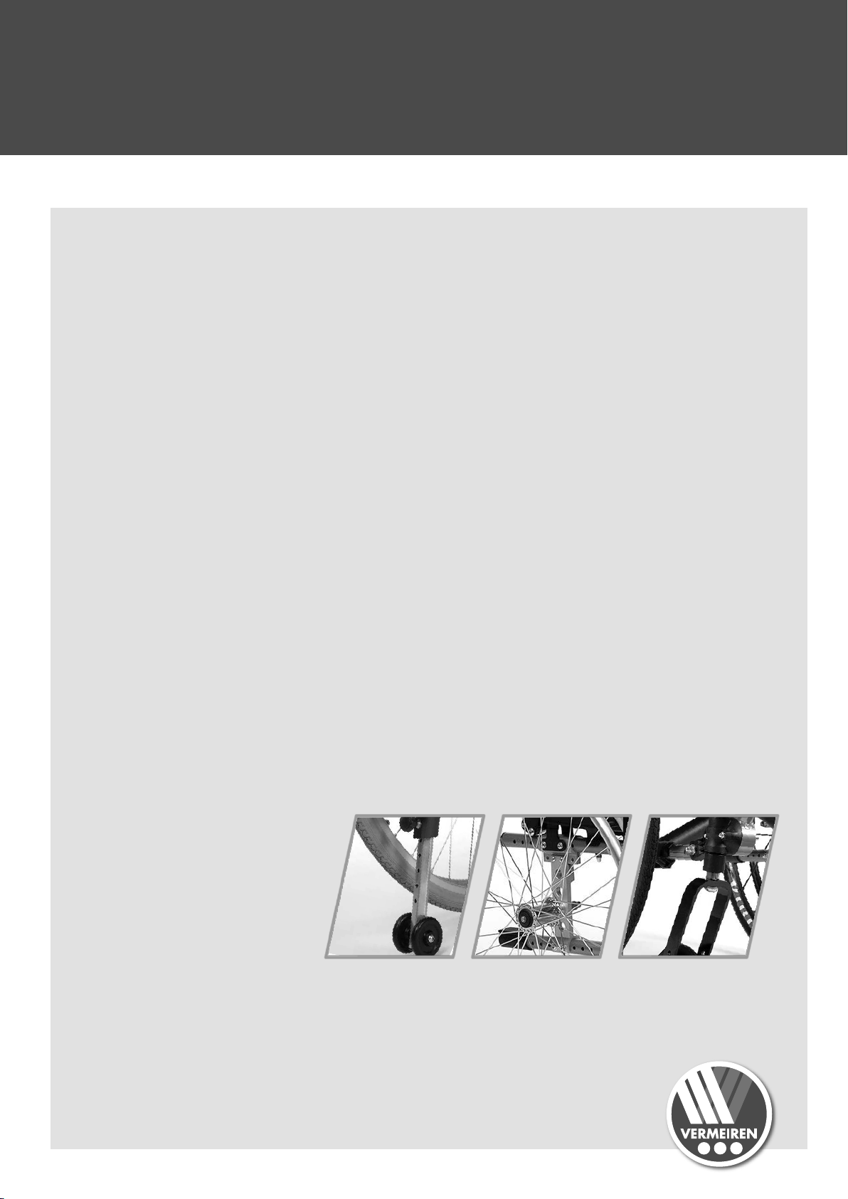
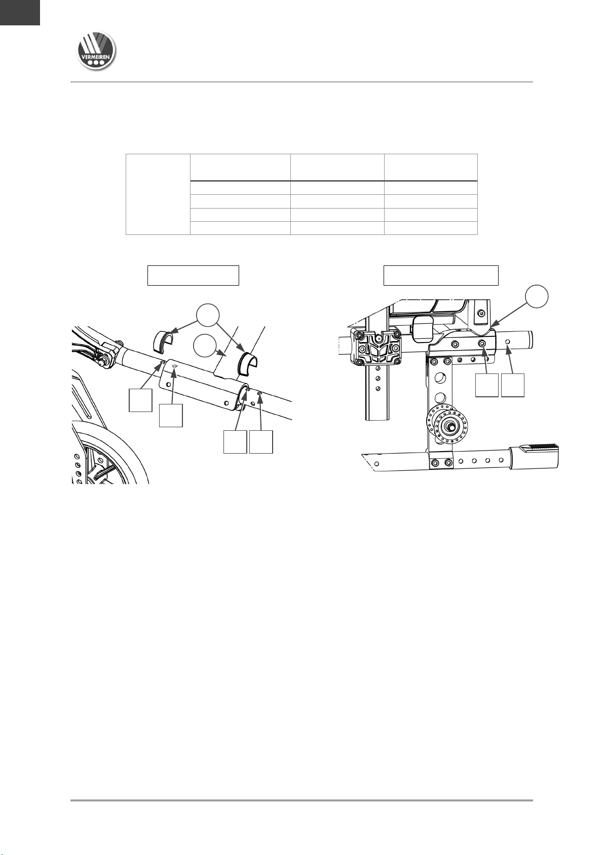
Adjust the position of the rear wheel as follows:
1. Remove the 4 socket screws located in the holes (2) of
mounting plate (1).
2. Move the mounting plate to the front or rear within the range
of the adjustment holes.
3. Retighten the 4 socket screws in holes (2).
advised to mount the mounting plate (1) of rear
most rear position.
two anti-tipping rollers (2) if the wheelchair is to
moved with inclined backrest.
2
3.3 Seat height and angle
3.3.1 Adjustment settings
The seat of the V300 & V500 wheelchairs are adjustable in heights and angle (0°-2,5°-5°7,5°-10°). The adjustment settings depend on the wheelchair model as collected in table 1 up
to table 3 in this section. Each table is followed by an illustration of the adjustment points.
The adjustment procedures are explained in §3.3.2.
The values in the tables are for the default seat angle of 5°. For other seat angle - seat height
combinations, the same table can be used. If you don't find the right seat angle - seat height
combination, please contact Vermeiren.
The adjustment of seat height and seat angle is based on (see also following figure):
• Relocating bushing (B) to a position above or under the housing (C) of the castor
axle;
• Mounting front wheel higher of lower in the front fork (A);
• Mounting the rear wheel higher or lower in the mounting plate (D).
Installation manual
- 5 -

EN
NL
PL
CS
Table 1: V300DC V300XL, V300F, V300 DL
Seat height
Rear wheels
Front wheels
Hole
Hole
Bushing (B)
440 mm
1
6
Above (C)
470 mm
2
6
Under (C)
500 mm
(Default)
3
7
Under (C)
530 mm
4
8
Under (C)
Seat height
Rear wheels
Front wheels
Hole
Hole
Bushing (B)
440 mm
1
8
Above (C)
470 mm
2
8
Under (C)
500 mm
(Default)
3
10
Under (C)
530 mm
(6” wheels)
4
10
Under (C)
D B C
A
C B A
Seat height
Other seat
height
At seat angle 5° (Default setting)
Rear wheels Front wheels
V-series wheelchairs
2018-10
Adjustments
1
2
3
4
Table
2: V300XR, V300ACT (see next page)
At seat angle 5° (Default setting)
6
7
8
440 mm
Installation manual
- 6 -

EN
NL
PL
CS
Rear wheels Front wheels
Seat height
Rear wheels
Front wheels
Hole
Hole no.
Ø
Bushing (B)
440 mm
1
7
150 mm
Above (C)
470 mm
2
7
150 mm
Under (C)
500 mm
(Default)
3
9
150 mm
Under (C)
530 mm
4
10
200 mm
Under (C)
B
C
A
C
B
A
Other seat height
Seat height 440 mm
D B C
A
C
B
A
Seat height
Other seat
D
V-series wheelchairs
2018-10
Adjustments
3
1
2
4
Table 3: V300, V500, V500XL
At seat angle 5° (Default setting)
8
10
Rear wheels Front wheels
3
4
1
2
440 mm
Installation manual
- 7 -
7
9
10
height

EN
NL
PL
CS
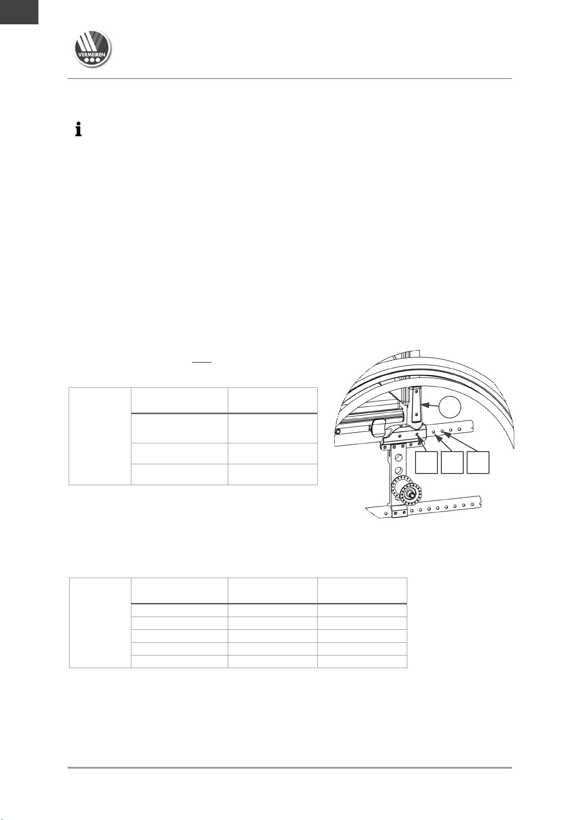
3.3.2 Adjusting rear and front wheel height
D
E
B C 31
F
A
Adjust the rear-wheel height as follows:
V-series wheelchairs
2018-10
Adjustments
1. Remove the rear wheels (see instruction manual).
2. Demount the axle housings (E) of the rear wheels from axle
plate (D) and remount in the correct hole, see tables in §3.3.1.
3. Repeat this for the second rear wheel. Make sure both housings
are positioned identically.
4. Verify that both axle housings (E) are tightened firmly.
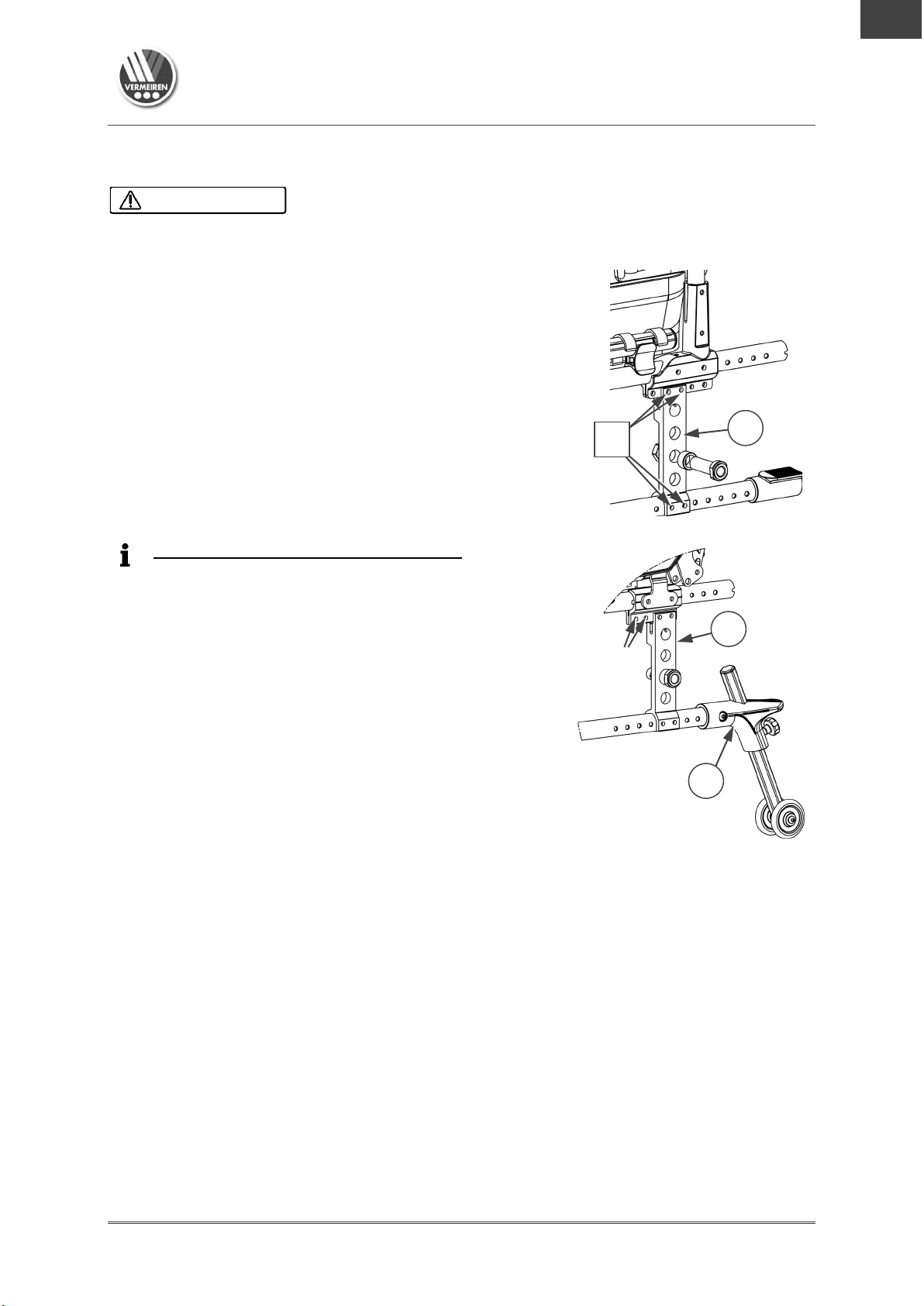
Adjust the front wheel height as follows:
1. Remove the cover cap from the frame tube.
2. Remove the nut (31) of the swivel axle
3. Demount the front wheel and remount it in the correct hole of front fork
(A) according to the tables in §3.3.1.
4. Verify that the location of the bushing (B) is correct in relation to the
swivel-axle housing (C), see tables in §3.3.1.
5. Mount the swivel axle (F) back in the housing (C) with bushing (B) at
the correct position, see the exploded view. Tighten nut (31) firmly.
6. Check the tension of the swivel axle (F); make sure it turns smoothly,
without play.
7. Repeat this for the second front wheel. Make sure both front wheels are
positioned identically.
(F) and collect the loose parts.
3
4
1
2
Final adjustment
1. Insert the rear wheels.
2. If installed properly, the swivel axles of the front wheels stand
perpendicular to the ground. To adjust the angle of the swivel axles,
follow the instruction in next section.
3. Finally, adjust the brakes according to the instruction in § 3.4.
Installation manual
- 8 -
V-series wheelchairs
EN
NL
PL
CS
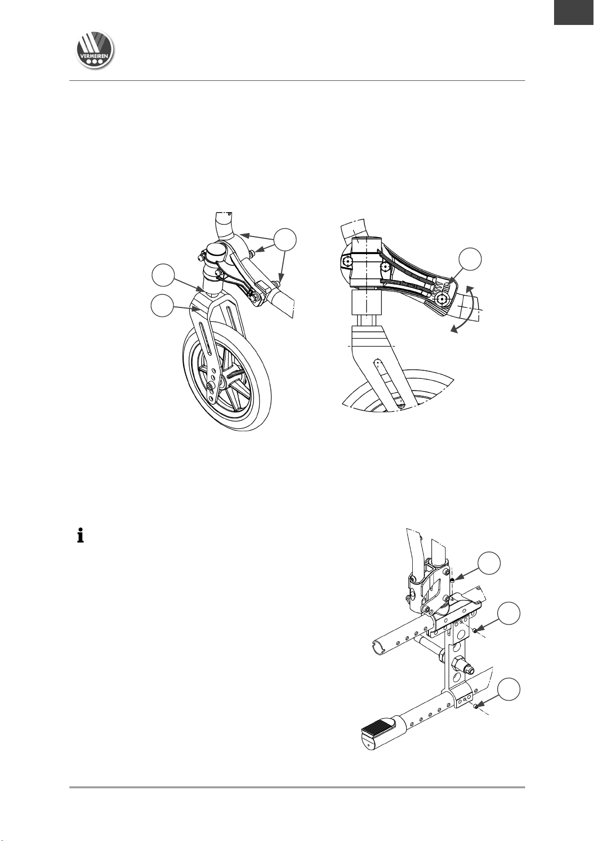
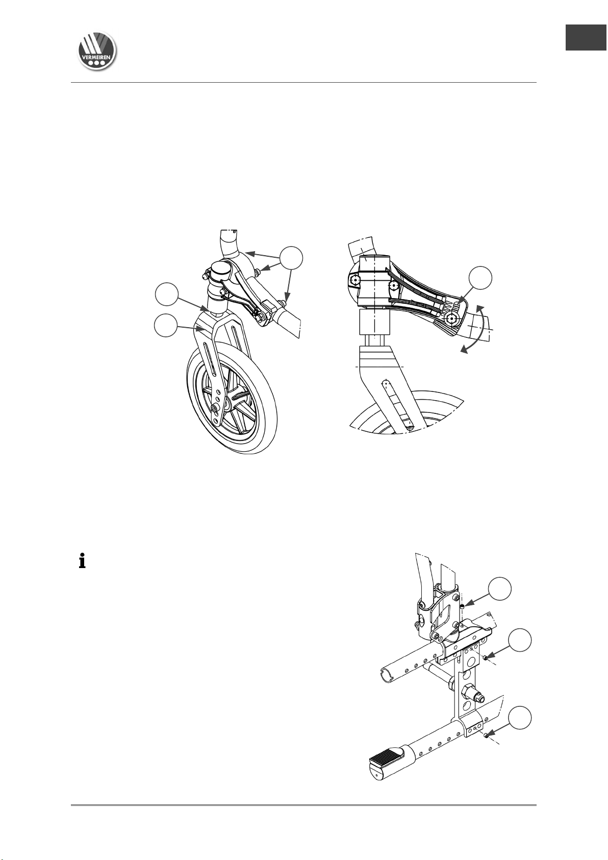
Important remark
When adjusting the backrest connection, make sure
that all 3 connection screws (
tightened firmly.
To prevent that
react on the wheelchair frame, the connection
screws
coating
G
F A 15
59
59
59
2018-10
Adjustments
3.3.3 Adjusting swivel axles
Verify that the swivel axle (F) stands perpendicular to the ground. If not, adjust the swivel
axle at toothed clamp (G) as follows:
1. Loosen the three socket screws (15).
2. Adjust the angle of the swivel axle until it is perpendicular to the ground. There are 5
positions available, each indicated by a small triangle.
3. Tighten the 3 socket scr ews (15) firmly and repeat this for the second swivel axle.
3.4 Seat depth
The procedure of this adjustment is explained in §3.4.1.
The adjustment settings depend on the wheelchair model as collected in the tables in section
§3.4.2, §3.4.3 and §3.4.4. Each table is followed by an illustration of the adjustment points.
item 59, in example) are
theft-protection systems in shops
(59) must be turned through the frame
!
View from the inside
Installation manual
- 9 -
V-series wheelchairs
EN
NL
PL
CS
The settings and item numbers can be found in following
Seat depth
Backrest
position holes
490 mm
1
510 mm
2
530 mm
3
Cross position
holes
Backrest
position holes
460 mm
Hole 1 and 3
1
440 mm (Default)
Hole 2 and 4
1
500 mm
Hole 1 and 3
2
480 mm
Hole 2 and 4
2
520 mm
Hole 1 and 3
3
A
2018-10
Adjustments
3.4.2 Adjustment of cross and backrest connection
sections
Cross position (if adjustable)
1. Remove clip (10), at each side of the wheelchair.
2. Move the cross (X) forwards/backwards to the desired position according to the settings
in the tables of previous sections.
3. Replace both clips (10) at each side of the wheelchair to lock the cross position.
Backrest-connection position
1. Demount both socket screws of the backrest connection, at both sides of the wheelchair.
2. Move the backrest connection (A/B/C/D) forwards/backwards to the desired position
according to the settings in the tables of previous sections.
3. Mount the 2 socket screws firmly; at both sides of the wheelchair.
4. Verify if seat height and seat angle are correctly set.
3.4.3 Seat depth option 1
This type of wheelchair is only adjustable in 3 seat
depths by adjusting the backrest connection (A).
V300XL
3.4.4 Seat depth option 2
This type of wheelchair is adjustable in 5 seat depths by adjusting the location of the frame
cross (X) and backrest connection (B), see picture on next page.
V300 30°
(Default)
Seat depth
1 3 2
Installation manual
- 10 -

V-series wheelchairs
EN
NL
PL
CS
Cross position
holes
Backrest
position holes
460 mm
Hole 1 and 3
1
440 mm (Default)
Hole 2 and 4
1
500 mm
Hole 1 and 3
2
480 mm
Hole 2 and 4
2
520 mm
Hole 1 and 3
3
B
X
10
Cross position
Backrest position
Cross position
Backrest position
X 1 10
C
2018-10
Adjustments
1
2
4 3
3.4.5 Seat depth option 3
This type of wheelchair is adjustable in 5 seat depths by adjusting the location of the frame
cross (X) and backrest connection (C).
V300
V300DC
V300F
V300ACT
V300XR
V300DL
Seat depth
1 3 2
1 3 2
2
4 3
Installation manual
- 11 -
V-series wheelchairs
EN
NL
PL
CS
Cross position
holes
Backrest
position holes
460 mm
Hole 1 and 3
Position 1
440 mm (Default)
Hole 2 and 4
Position 1
500 mm
Hole 1 and 3
Position 2
480 mm
Hole 2 and 4
Position 2
D
X
10
Cross position
Backrest position
2018-10
Adjustments
3.4.6 Seat depth option 4
This type of wheelchair is adjustable in 4 seat depths by adjusting the location of the frame
cross (X) and backrest connection (D).
V500
1
2
Seat depth
1 2
4 3
Installation manual
- 12 -

EN
NL
PL
CS
3.5 Parking brakes
Risk of injuries
Always adjust the parking brakes after adjustment of rear-wheel position. Readjust also when
tyres are worn, to compensate the wear.
22
21
23
21
22
23
V300
V300 30°
V300DC
V300XL
V300F
V300ACT
V300XR
V300DL
V500
V-series wheelchairs
2018-10
Adjustments
CAUTION
Adjust the correct braking force
1. Release the brake with lever (21), see instruction manual.
1. Loosen socket screws (22) to make the brake free to slide.
2. Slide the brake over the guide (23) to the desired position.
3. Retighten the socket screws (22).
4. Verify if the brake is working properly: the wheel is blocked, but the brake can be operated
easily. If this is not the case repeat th e steps above..
5. Repeat this adjustment for the second parking brake. Make sure both brakes are adjusted
identically.
Installation manual
- 13 -

EN
NL
PL
CS
3.6 Footrest length
Since they are connected, b
Risk of damage
Make sure that the footrests won’t touch the ground.
Keep a minimum safe distance of 60 mm above the ground.
The maximum length of the footrest is limited to the length
indicated by a triangle on the front of the footrest tube, see
picture.
24
V300 XL
24
V300 – V500
25
26
27
V-series wheelchairs
2018-10
Adjustments
CAUTION
oth footrests of V300XL are adjusted simultaneously.
Adjust the length as follow:
1. Remove the socket screw (24) on
the back of the footrest.
2. Adjust the footrest to a comfortable
length.
3. Retighten the socket screw firmly.
4. Repeat this for the second footrest.
Make sure the footrests are
positioned identically.
3.7 Footplate position
The footplate(s) can be used in 2 positions: front and rear. Default, each footplate is adjusted
with its base plate in the rear position.
To place the footplate in front position:
1. Remove the socket screws (25) of both footplates.
2. Exchange left and right footplate.
3. Tighten the socket screws (25) firmly.
3.8 Footplate angle
Adjust the angle of the footplate at its toothed clamp:
1. Loosen socket screw (25) on footrest (26).
5. Turn the footplate in the desired angle (80°- 100°).
The dashes (27) on the toothed clamp indicate the
angular positions.
6. Retighten the socket screw.
7. Repeat this for the second footplate.
Installation manual
- 14 -

V-series wheelchairs
EN
NL
PL
CS
Height arm pad to seat
Number of blocks
below tube
Number of blocks
between tube and arm pad
220 mm (Default)
2
1
230 mm
1
2
240 mm
0
3
Depth of the arm pad
Used holes
Front position
Back and middle
Middle position (Standard)
Hole 2 and 4
Back position
Front and middle
35
34
2018-10
Adjustments
3.9 Arm pad height and depth (option 1)
This arm pad (see picture on next page) is adjustable in height and depth, each in 3
positions. The height is adjusted by adding or removing distance blocks. The depth is
adjusted by using different mounting holes.
To adjust:
1. Remove both socket screws (34).
2. Place the correct number of blocks below and above the frame tubes, see table 1.
3. For depth adjustment, install the arm pad by using the correct mounting holes, see table 2.
Table 1
Table 2
3.10 Arm pad depth (option 2)
Adjust the depth of the arm pad as follow (range
120 mm: step less):
1. Loosen both socket screws (35) at the bottom
of the arm pad.
2. Move the arm pad to the front or rear within
the range of the slotted holes (42,5 mm).
If this not enough, loosen the socket screws
and attach the arm pad using the other holes
(3 positions available).
3. Tighten both socket screws firmly.
4. Repeat this for the second arm pad. Make sure both arm pads are positioned identically.
Installation manual
- 15 -

EN
NL
PL
CS
3.11 Armrest height (option 3)
36
The height of the armrest is adjustable in 6 positions as
follows:
1. Pull the armrest out of the armrest holder.
2. Remove socket screw (36) that sets the height.
3. Mount the screw in the desired hole.
4. Insert the armrest in the armrest holder.
5. Check the height; readjust if necessary.
6. Repeat this for the second armrest. Make sure both
armrests are positioned identically.
V-series wheelchairs
2018-10
Adjustments
Installation manual
- 16 -

Fauteuils roulants série V
EN
FR
NL
2018-10
Table des matières
Table des matières
Préface ....................................................................................................................... 2
1 Portée de la livraison .................................................................................... 3
2 Outils .............................................................................................................. 3
3 Réglages ........................................................................................................ 4
3.1 Stabilité et maniabilité ..................................................................................... 4
3.2 Position de roue arrière ................................................................................... 5
3.3 Hauteur et inclinaison du siège ....................................................................... 5
3.3.1 Paramètres de réglage ....................................................................................... 5
3.3.2 Réglage de la hauteur des roues arrière et avant .............................................. 8
3.3.3 Réglage des axes de pivot ................................................................................. 9
3.4 Profondeur du siège ........................................................................................ 9
3.4.2 Réglage de la croix et du raccord du dossier ................................................... 10
3.4.3 Profondeur de siège option 1 ............................................................................ 10
3.4.4 Profondeur de siège option 2 ............................................................................ 10
3.4.5 Profondeur de siège option 3 ............................................................................ 11
3.4.6 Profondeur de siège option 4 ............................................................................ 12
3.5 Freins de stationnement ............................................................................... 13
3.6 Longueur de cale-pied .................................................................................. 13
3.7 Position du repose-pied ................................................................................ 14
3.8 Inclinaison du repose-pied ............................................................................ 14
3.9 Hauteur et profondeur de manchette (option 1) ............................................ 14
Profondeur d'accoudoir (option 2) .......................................................................... 15
3.10 Hauteur d'accoudoir (option 3) ...................................................................... 16
Manuel d'installation
- 1 -
Fauteuils roulants série V
EN
FR
NL
Manuel d'utilisation
Pour l'utilisateur et le revendeur spécialisé
Instructions d'installation (instructions relatives aux réglages des détails)
Pour le revendeur spécialisé
Tableau de couples (couples maximums des boulons et des écrous)
Pour le revendeur spécialisé
Dessins des pièces (de rechange)
Pour le revendeur spécialisé
2018-10
Préface
Préface
Ce manuel d'installation vous est fourni pour vous aider à installer et à réparer ce fauteuil
roulant, ce manuel est offert. Veuillez le lire attentivement. Si vous avez encore des questions
après la lecture de ce manuel, n’hésitez pas à prendre contact avec Vermeiren.
Les informations du présent manuel s'appliquent à tous les fauteuils roulants selon la liste
suivante :
• V300
• V300 30°
• V300 30° Comfort
• V300 HEM2
• V300 XL
• V300ACT / V300XR
• V300D
• V300DC
• V300DL
• V300F
• V300GO
• V500
• V500 30°
• V500XL
Des images du produit sont utilisées pour clarifier les instructions. Les détails du produit illustré
peuvent diverger de votre produit.
Sur notre site Internet http://www.vermeiren.com/
récente des informations suivantes. Veuillez consulter régulièrement ce site Internet pour
d'éventuelles mises à jour.
Les personnes malvoyantes peuvent télécharger la version électronique de ce manuel et la
lire au moyen d'une application de texte-parole.
, vous trouverez toujours la version la plus
Manuel d'entretien des fauteuils roulants
Pour le revendeur spécialisé
Manuel d'installation
- 2 -

Fauteuils roulants série V
EN
FR
NL
2018-10
Portée de la livraison
1 Portée de la livraison
Les éléments suivants sont compris dans la livraison.
• Le châssis, y compris les roues, le cadre de dossier, le siège (hauteur du siège par
défaut 500 mm, inclinaison du siège par défaut 5°)
• 2 accoudoirs (pas pour V300XR)
• Coussin de siège (uniquement pour V300 DL)
• Anti-bascule (uniquement pour V300 DL)
• 1 paire de cale-pieds/1 cale-pied complet
• Outils
• Manuel
• Accessoires
Veuillez noter que la configuration de base peut différer dans les différents pays européens.
Prenez contact avec votre revendeur spécialisé.
2 Outils
Pour réparer et régler le fauteuil roulant, les outils suivants sont nécessaires :
• Jeu de clés n
• Jeu de clés Allen n
• Tournevis cruciforme
• Tournevis n
os
os
4 à 6
7 à 22
os
3 à 8
Manuel d'installation
- 3 -
EN
FR
NL
3 Réglages
Remarque importante
• Pour de plus amples informations, prenez contact avec Vermeiren, cf. le site Internet
http://www.vermeiren.com/.
Risque de basculement
Tenez compte que changer la position des roues arrière peut influencer la stabilité du
fauteuil roulant. Si vous réglez les roues arrière
1.
2. en position de réglage avant, il devient moins stable mais plus maniable.
Risque de blessures ou de dommages
• Lisez le manuel d'utilisation du fauteuil roulant spécifique.
•
•
•
•
•
•
vous de ne coincer aucun objet
•
•
•
Toute dérogation aux paramètres de réglage peut influencer la stabilité du fauteuil roulant
•
Tableau de couples sur notre site Internet.
Fauteuils roulants série V
2018-10
Réglages
ATTENTION
Tenez compte des détails techniques et des limites d'utilisation prévues; cf. le manuel
d'utilisation.
Le fauteuil roulant doit être réglé par un revendeur spécialisé selon les instructions du
présent manuel.
Toute modification au produit annulera la garantie et mettra fin à la responsabilité de
Vermeiren.
N'utilisez que les pièces et outils décrits dans ce manuel.
Assurez-vous qu'aucune personne aux alentours ne pénètre dans la zone de travail.
Lorsque vous réglez et utilisez le fauteuil roulant, assurez-
ni aucune partie de votre corps entre les pièces mobiles.
Utilisez uniquement les paramètres de ce manuel.
Assurez-vous que le réglage est identique à gauche et à droite du fauteuil roulant.
et présenter un risque de renversement ou de chute.
Assurez-vous que toutes les vis sont bien serrées avant d'utiliser le fauteuil
roulant. Pour les vis, respectez les couples de serrage qui figurent dans le
3.1 Stabilité et maniabilité
ATTENTION
en position de réglage arrière, le fauteuil roulant devient plus stable, mais moins
maniable ;
Pour augmenter la stabilité et la maniabilité, les réglages suivants peuvent être effectués :
• Position de roue arrière, cf. §3.2.
• Hauteur et inclinaison du siège, cf. §3.3
Manuel d'installation
- 4 -

EN
FR
NL
3.2 Position de roue arrière
Risque de blessures ou de
Après réglage des roues arrière, vérifiez le fonctionnement des freins et ajustez selon le §
.
Uniquement pour le V300 30° et selon l'utilisation :
Nous recommandons d'installer la plaque de montage
(1) des roues arrière dans la position la
Installez deux roues anti
roulant doit être déplacé avec un dossier incliné.
1
2
1
Fauteuils roulants série V
2018-10
Réglages
ATTENTION
Réglez la position de la roue arrière comme suit :
1. Retirez les 4 vis à tête creuse situées dans les trous (2) de
la plaque de montage (1).
2. Déplacez la plaque de montage vers l'avant ou l'arrière
dans la plage des trous de réglage.
3. Resserrez les 4 vis à tête creuse dans les trous (2).
plus arrière.
-bascule (3) si le fauteuil
dommages
3.5
2
3.3 Hauteur et inclinaison du siège
3.3.1 Paramètres de réglage
Le siège des fauteuils roulants V300 et V500 est réglable en hauteur et en inclinaison (0°2,5°-5°-7,5°-10°). Les paramètres de réglage dépendent du modèle de fauteuil roulant et
figurent aux tableaux 1 à 3 de cette partie. Chaque tableau est suivi d'une illustration des
points de réglage. Les procédures de réglage sont expliquées au §3.3.2.
Les valeurs présentées dans les tableaux sont valables pour l'inclinaison du siège par défaut
de 5°. Le même tableau peut être utilisé pour d'autres combinaisons d'inclinaison - hauteur
de siège. Si vous ne trouvez pas la bonne combinaison d'inclinaison - hauteur de siège,
veuillez prendre contact avec Vermeiren.
Le réglage de la hauteur et de l'inclinaison du siège est basé sur (cf. également la figure
suivante) :
• La réinstallation de la douille (B) à une position supérieure ou inférieure du logement
(C) de l'axe de roulette ;
• Le montage de la roue avant plus haut ou plus bas dans la fourche avant (A);
Manuel d'installation
- 5 -

Fauteuils roulants série V
EN
FR
NL
Hauteur de
siège
Roues arrière
Roues avant
Trou
Trou
Douille (B)
440 mm
1
6
Au-dessus (C)
470 mm
2
6
En dessous (C)
500 mm
(Par défaut)
3
7
En dessous (C)
530 mm
4
8
En dessous (C)
Hauteur de
siège
Roues arrière
Roues avant
Trou
Trou
Douille (B)
440 mm
1
8
Au-dessus (C)
470 mm
2
8
En dessous (C)
500 mm
(Par défaut)
3
10
En dessous (C)
530 mm
(6” roues)
4
10
En dessous (C)
D
B C A
C
B
A
Hauteur de
440 mm
Autre
siège
• Le montage de la roue arrière plus haut ou plus bas dans la plaque de montage (D).
Tableau 1 : V300DC V300XL, V300F, V300 DL
Inclinaison de 5° au siège (paramètre par défaut)
Roues arrière Roues avant
2018-10
Réglages
1
2
3
4
Tableau
2 : V300XR, V300ACT (cf. page suivante)
Inclinaison de 5° au siège (paramètre par défaut)
siège de
6
7
8
hauteur de
Manuel d'installation
- 6 -

Fauteuils roulants série V
EN
FR
NL
Hauteur de
Roues arrière
Roues avant
Trou
Trou no
Ø
Douille (B)
440 mm
1
7
150 mm
Au-dessus (C)
470 mm
2
7
150 mm
En dessous
(C)
500 mm
(Par défaut)
3
9
150 mm
En dessous
(C)
530 mm
4
10
200 mm
En dessous
(C)
B
C
A
C
B
A
Autre hauteur de
Hauteur de siège de
D B C
A
C B A
Hauteur de
Autre hauteur
D
Roues arrière Roues avant
2018-10
Réglages
3
1
2
4
440 mm
Tableau 3 : V300, V500, V500XL
Inclinaison de 5° au siège (paramètre par défaut)
siège
8
10
siège
Roues arrière Roues avant
3
4
1
2
siège de 440
Manuel d'installation
- 7 -
7
9
10
de siège

EN
FR
NL
3.3.2 Réglage de la hauteur des roues arrière et avant
D
E
B C 31
F
A
Réglez la hauteur des roues arrière de la manière suivante :
Fauteuils roulants série V
2018-10
Réglages
1. Retirez les roues arrière (cf. le manuel d'utilisation).
2. Démontez les logements d'axe (E) des roues arrière de la
plaque d'axe (D) et remontez-les dans le trou correct, cf. les
tableaux au §3.3.1.
3. Répétez l'opération pour la deuxième roue arrière. Assurezvous que les deux logements sont positionnés identiquement.
4. Vérifiez que les deux logements d'axe (E) sont bien serrés.
Réglez la hauteur des roues avant de la manière suivante :
1. Retirez le bouchon de protection du tube de châssis.
2. Retirez l'écrou (31) de l'axe de pivot (F) et récupérez les pièces
déserrées.
3. Démontez la roue avant et remontez-la dans le trou correct de la
fourche avant (A) conformément aux tableaux au §3.3.1.
4. Vérifiez si l'emplacement de la douille (B) est correct par rapport au
logement de l'axe de pivot (C), cf. les tableaux au §3.3.1.
5. Remontez l'axe de pivot (F) dans le logement (C) avec la douille (B) à
la position correcte, cf. la vue éclatée. Serrez bien l'écrou (31).
6. Vérifiez la tension de l'axe de pivot (F) ; assurez-vous qu'il tourne sans
à-coups, sans jeu.
7. Répétez l'opération pour la deuxième roue avant. Assurez-vous que les
deux roues avant sont positionnées identiquement.
3
4
1
2
Réglage final
1. Insérez les roues arrière.
2. S'ils sont installés convenablement, les axes des roues avant sont
perpendiculaires au sol. Pour régler l'inclinaison des axes de pivot,
suivez les instructions à la section suivante.
3. Enfin, réglez les freins conformément aux instructions au § 3.4.
Manuel d'installation
- 8 -
Fauteuils roulants série V
EN
FR
NL
Remarque importante
Lors du réglage du raccord du dossier, assurez
que les 3 vis (point 59, dans l'exemple) sont bien
serrées.
Pour éviter que les systèmes de protection antivol ne
réagissent au châssis du fauteuil roulant, les vis (59)
doivent être tournées
châssis
G
F A 15
59
59
59
2018-10
Réglages
3.3.3 Réglage des axes de pivot
Vérifiez que l'axe de pivot (F) est perpendiculaire au sol. Si ce n'est pas le cas, réglez l'axe
de pivot au dispositif denté (G) de la manière suivante :
1. Desserrez les trois vis à tête creuse (15).
2. Réglez l'inclinaison de l'axe de pivot jusqu'à ce qu'il soit perpendiculaire au sol. Il y a 5
positions disponibles, chacune est indiquée par un petit triangle.
3. Serrez bien les 3 vis à tête creuse (15), et répétez l'opération pour le deuxième axe de
pivot.
3.4 Profondeur du siège
La procédure de ce réglage est expliquée au §3.4.1.
Les paramètres de réglage dépendent du modèle de fauteuil roulant, cf. les tableaux §3.4.2,
§3.4.3 et §3.4.4 à cet effet. Chaque tableau est suivi d'une illustration des points de réglage.
!
à travers le revêtement du
-vous
Vue de l'intérieur
Manuel d'installation
- 9 -

Fauteuils roulants série V
EN
FR
NL
Vous trouverez les paramètres et
Profondeur du
Trous de
dossier
490 mm
1
510 mm
2
530 mm
3
Trous de
dossier
460 mm
Trous 1 et 3
1
440 mm
(Par défaut)
Trous 2 et 4
1
500 mm
Trous 1 et 3
2
480 mm
Trous 2 et 4
2
520 mm
Trous 1 et 3
3
A
2018-10
Réglages
3.4.2 Réglage de la croix et du raccord du dossier
numéros d'article dans les sections suivantes
Position de la croix (si réglable)
1. Retirez le clip (10), de chaque côté du fauteuil roulant.
2. Déplacez la croix (X) vers l'avant/arrière à la position souhaitée conformément aux
indications des tableaux des parties précédentes.
3. Replacez les deux clips (10) de chaque côté du fauteuil roulant pour verrouiller la position
de la croix.
Position du raccord du dossier
1. Démontez les deux vis à tête creuse du raccord du dossier, des deux côtés du fauteuil
roulant.
2. Déplacez le raccord du dossier (A/B/C/D) vers l'avant/arrière à la position souhaitée
conformément aux indications des tableaux des parties précédentes.
3. Serrez les 2 vis à tête creuse ; des deux côtés du fauteuil roulant.
4. Vérifiez si la hauteur et l'inclinaison du siège sont réglées correctement.
3.4.3 Profondeur de siège option 1
Ce type de fauteuil roulant est uniquement réglable à
3 profondeurs de siège en ajustant le raccord du
dossier (A).
siège
V300XL
3.4.4 Profondeur de siège option 2
Ce type de fauteuil roulant est réglable à 5 profondeurs de siège en modifiant l'emplacement
de la croix du châssis (X) et le raccord du dossier (B), cf. photo à la page suivante.
(Par défaut)
Profondeur du
siège
position de
Trous de
position de croix
position de
1 3 2
V300 30°
Manuel d'installation
- 10 -
 Loading...