

Page 1

VERMEIREN
V200
INSTRUCTION MANUAL
MODE D’EMPLOI
GEBRUIKSAANWIJZING
GEBRAUCHSANWEISUNG
ISTRUZIONI PER L'USO
MANUAL DE INSTRUCCIONES
INSTRUKCJA OBSŁUGI
Page 2

EN
Inst r uc tions to the s pe cialist deale r
This instruction manual is part and parcel of the product and must accompany every wheelchair sold.
Version: A, November 2010
All rights reserved, including translation.
No part of this manual may be reproduced in any form what so ever (print, photocopy, microfilm or
any other process) without written permission of the publisher, or processed, duplicated or distributed
by using electronic systems.
© N.V. Vermeiren N.V. 2010
Page 3

EN
V200
2010-11
Page%1%
Contents
Preface . . .. . .. . . .. . . .. . . .. . . .. . . .. . . .. . . .. . . . . . .. . . .. . . .. . . .. . . .. . . .. . . .. . . .. . .. . . .. . . .. . . .. . . .. . . .. . . .. . 2!
1! Productdesc r iption .. . . .. . . .. . . .. . . .. . . .. . .. . . .. . . .. . . .. . . .. . . .. . . .. . . .. . . .. . .. . . .. . . . 3!
1.1! Intended Use ................................................................................................................ 3!
1.2! Technical specifications .............................................................................................. 4!
1.3! Drawing ....................................................................................................................... 5!
1.4! Accessories .................................................................................................................. 6!
1.5! Location identification plate........................................................................................ 6!
1.6! Explanation of symbols ............................................................................................... 6!
2! Use .. . . . . . .. . . .. . . .. . . .. . . .. . . .. . . . . . . . . . .. . . .. . . .. . . .. . . .. . . .. . .. . . .. . . .. . . .. . . .. . . .. . . .. . . .. . . . 7!
2.1! Carrying the wheelchair .............................................................................................. 7!
2.2! Mounting the rear wheels ............................................................................................ 7!
2.3! Unfolding the wheelchair ............................................................................................ 7!
2.4! Mounting or removing of the footrests ....................................................................... 8!
2.5! Operating the brakes.................................................................................................... 8!
2.6! Mounting or removing of arm supports ...................................................................... 9!
2.7! Transfer in and out the wheelchair ............................................................................ 11!
2.8! Correct position in the wheelchair ............................................................................ 11!
2.9! Riding the wheelchair................................................................................................ 11!
2.10! Moving on slopes ...................................................................................................... 12!
2.11! Negotiating steps or kerbs ......................................................................................... 12!
2.12! Fold up the wheelchair .............................................................................................. 15!
2.13! Taking off the wheels ................................................................................................ 15!
2.14! Transport in the car .................................................................................................... 15!
2.15! Use of the wheelchair as seat in a motor vehicle ...................................................... 16!
3! Installation and adjustment . . .. . .. . . .. . . .. . . .. . . .. . . .. . . .. . . .. . . . . . .. . . .. . . .. . 18!
3.1! Tools .......................................................................................................................... 18!
3.2! Manner of delivery .................................................................................................... 19!
3.3! Adjusting the seat height and seat angle ................................................................... 19!
3.4! Adjusting the seat depth ............................................................................................ 22!
3.5! Adjust the brakes ....................................................................................................... 23!
3.6! Adjusting of the footrests .......................................................................................... 24!
3.7! Adjusting the arm support ......................................................................................... 25!
4! Mainte nance ... . . .. . . .. . . . . . .. . . .. . . .. . . .. . . .. . . .. . . . . . .. . . .. . . .. . . .. . . .. . . .. . . .. . . . . . .. 26!
4.1! Regular Maintenance................................................................................................. 26!
4.2! Shipping and storage ................................................................................................. 26!
4.3! Care ........................................................................................................................... 27!
4.4! Inspection .................................................................................................................. 28!
4.5! Disinfection ............................................................................................................... 29!
5! Guarantee . . . .. . . .. . . .. . . .. . . .. . . . . . .. . . .. . . .. . . .. . . .. . . .. . . . . . .. . . .. . . .. . . .. . . .. . . .. . . .. . 32!
6! Disposal . . .. . . .. . . .. . . .. . . .. . . .. . . .. . .. . . .. . . .. . . .. . . .. . . .. . . .. . . .. . .. . . .. . . .. . . .. . . .. . . .. . . 32!
7! Declaration of conformity .. . . .. . . .. . . .. . . .. . . .. . . . . . .. . . .. . . .. . . .. . . .. . . .. . . .. . 33!
8! Mainte nance plan . . .. . . .. . . .. . . .. . . .. . . .. . .. . . .. . . .. . . .. . . .. . . .. . . .. . . . . . .. . . .. . . .. . 34!
9! Disinfe c tion book .. . . .. . . .. . . .. . . .. . . .. . . . . . .. . . .. . . .. . . .. . . .. . . .. . . . . . .. . . .. . . .. . . .. 35!
Page 4

EN
V200
2010-11
Page%2%
Preface
First of all we want to thank you for putting your trust in us by selecting one of our
wheelchairs.
The Vermeiren wheelchairs are the result of many years of research and experience. During
the development, special attention was given to the ease of use and the serviceability of the
wheelchair.
The expected lifetime of 8 years for your wheelchair is strongly influenced by the care and
maintenance of the wheelchair.
This manual will help you get acquainted with the operation of your wheelchair.
Following the user instructions and the maintenance instructions are an essential part of the
guarantee.
This manual reflects the latest product developments. Vermeiren has the right to introduce
changes without the obligation to adapt or replace previously delivered models.
For any further questions, please consult your specialist dealer.
Page 5

EN
V200
2010-11
Page%3%
1 Productdescription
1.1 Intended Use
The wheelchair is intended for people with walking difficulties or no walking abilities.
The wheelchair is designed to transport 1 person.
The wheelchair is suited for indoor and outdoor use.
The user can propel the wheelchair by himself or have the wheelchair pushed by an
attendant.
The different types of fittings and accessories, and the modular construction allow full use by
persons disabled by:
paralysis
loss of limbs (leg amputation)
limb defects or deformations
stiff or damaged joints
heart insuffiencies and poor blood circulation
balance disturbances
cachexia (decrease in muscle)
and also for aged persons.
When providing for individual requirements:
body size and weight (max. 130kg (286.6 lb.))
physical and psychological condition
residential circumstances
environment
should be taken into consideration.
Your wheelchair should only be used on surfaces where all four wheels are touching the
ground and where there is sufficient contact to propel the wheels equally.
You should practice for use on uneven surfaces (cobblestones, etc.), slopes, curves and to
get past obstacles (kerbs, etc.).
The wheelchair should not be used as a ladder, nor is it a transport for heavy or hot objects.
When used on mats, carpeted floors or loose floor coverings, the floor covering can get
damaged.
Use only Vermeiren approved accessories.
The manufacturer is not liable for damage caused by the lack of or improper service or as a
result of not following instructions from this manual.
Compliance with the user and maintenance instructions are an essential part of the
guarantee conditions.
Page 6

EN
V200
2010-11
Page%4%
1.2 Technical specifications
Technical terms below are valid for the wheelchair in standard settings.
If other footrest / arm support or other accessories are used, the tabulated values will
change.
Make
Vermeiren
Address
Vermeirenplein 1/15, B-2920 Kalmthout
Type
Manual wheelchair
Model
V200
Maximum occupant mass
130 kg (286.6 lb.)
Description
Min.
Max.
Overall length with legrest
1010 mm (39.76 in.)
Effective seat width
390 mm
(15.35 in.)
420 mm
(16.54 in.)
440 mm
(17.32 in.)
460 mm
(18.11 in.)
480 mm
(18.90 in.)
500 mm
(19.69 in.)
Overall width (depends on the seat width)
590 mm
(23.23 in.)
620 mm
(24.41 in.)
640 mm
(25.20 in.)
660 mm
(25.98 in.)
680 mm
(26.77 in.)
700 mm
(27.56 in.)
Folded length
1000 m (39.37 in.)
Folded width
320 mm (12.60 in.)
Folded height
955 mm (37.60 in.)
Total mass
16,5 kg (36.38 lb.)
Mass of heaviest part
9 kg (19.84 lb.)
Static stability downhill
10° (in standard configuration)
Static stability uphill
7° (in standard configuration)
Static stability sideways
18° (in standard configuration)
Obstacle climbing
60 mm (2.36 in.)
Seat plane angle
0°
10°
Effective seat depth
440 mm (17.32 in.)
460 mm (18.11 in.)
Seat surface height at front edge
440 mm (17.32 in.)
530 mm (20.87 in.)
Backrest angle
90°
Backrest height
400 mm (15.75 in.)
Distance between footrest and seat
430 mm (16.93 in.)
Angle between seat and footrest
8°
Distance between armrest and seat
220 mm (8.66 in.)
240 mm (9.45 in.)
Front location of armrest structure
410 mm (16.14 in.)
Handrim diameter
535 mm (21.06 in.)
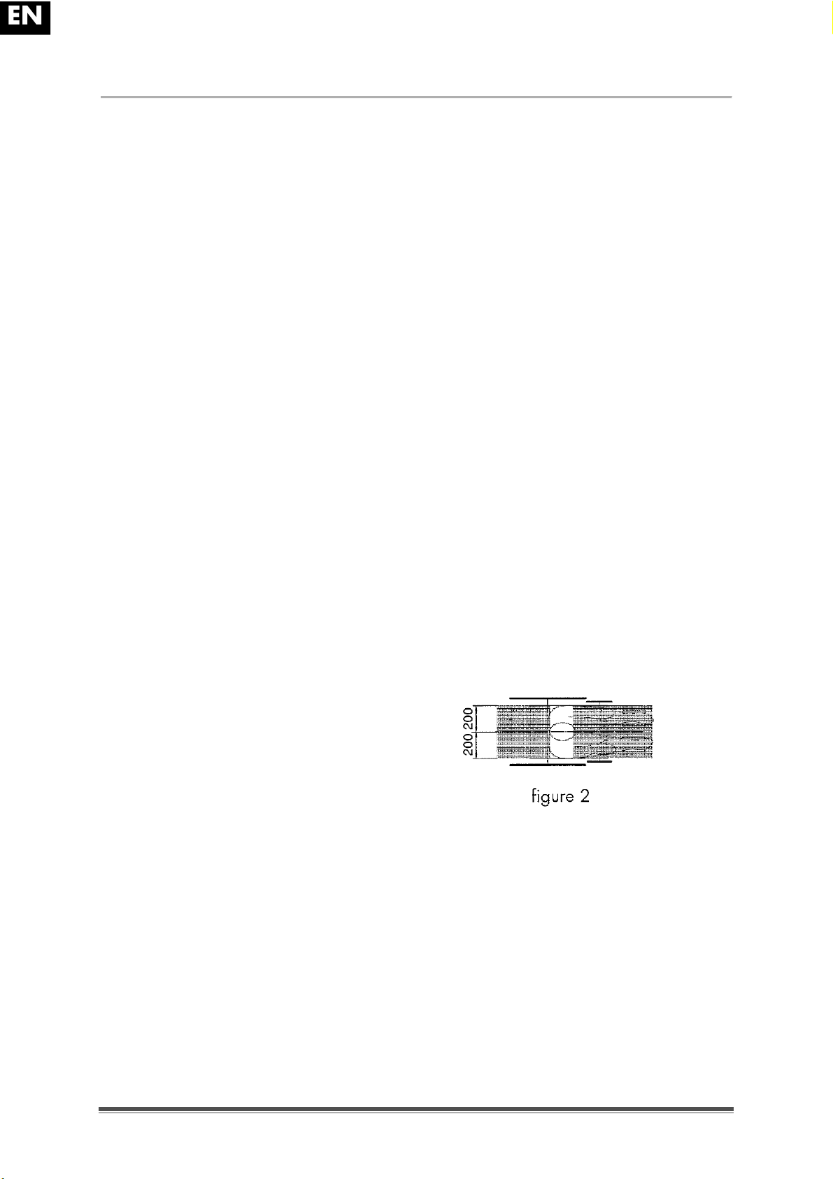
Horizontal location of axle (deflection)
50 mm (1.97 in.)
Minimum turning radius
1500 mm (59.06 in.)
Diameter Krypton PU Rear wheels
22"
24"
Tyre pressure, rear (driving) wheels
Max. 3.5 bar
Diameter Krypton PU steering wheels
200 mm (7.87 in.)
Tyre pressure, steering wheels
Max. 2.5 bar
Storage and use temperature
+ 5 °C (+41 °F)
+ 41 °C (+106 °F)
Storage and use humidity
30%
70%
We reserve the right to introduce technical changes. Measurement tolerance ± 15 mm / kg / ° (0.59 in. / 3,3 lb. / 1,5°)
Table 1: Technic al spec ific ations
Page 7

EN
V200
2010-11
Page%5%
The wheelchair complies to the requirements set up in:
ISO 7176-8: Requirements and test methods for static, impact and fatigue strengths.
ISO 7176-16: Resistance to ignition of upholstered parts
ISO 7176-19: Wheeled mobility devices for use as seats in motor vehicles.
1.3 Drawing
1 = Armrests
2 = Arm supports
3 = Footrests
4 = Brakes
5 = Steering wheels (front wheels)
6 = Driving wheels (rear wheels)
7 = Seat
8 = Back
9 = Tip cap
10 = Cross
11 = Handles
Page 8
EN
V200
2010-11
Page%6%
1.4 Accessories
The following accessories are available for the V200:
Anterior pelvic belt (B20) for mounting on the tubes of the back (see according
manual)
Anti-tipping device (B78) for mounting on the bottom frame (see according manual).
1.5 Location identification plate
1.6 Explanation of symbols
Maximum mass
Indoor and outdoor use
Down slope
Up slope
CE conformity
Page 9
EN
V200
2010-11
Page%7%
2 Use
This chapter describes the everyday use. These instructions are for the user and the
specialist dealer.
The wheelchair is delivered fully assembled by your specialist dealer. The instructions
intended for the specialist dealer on how to set up the wheelchair are given in § 3.
2.1 Carrying the wheelchair
The best way to carry the wheelchair is to make use of the wheels and roll the wheelchair.
If this is not possible (e.g. when the rear wheels are taken off for transportation in a car),
firmly grasp the frame on the front and the grips. Do not use the foot or arm rests or the
wheels to grasp the wheelchair.
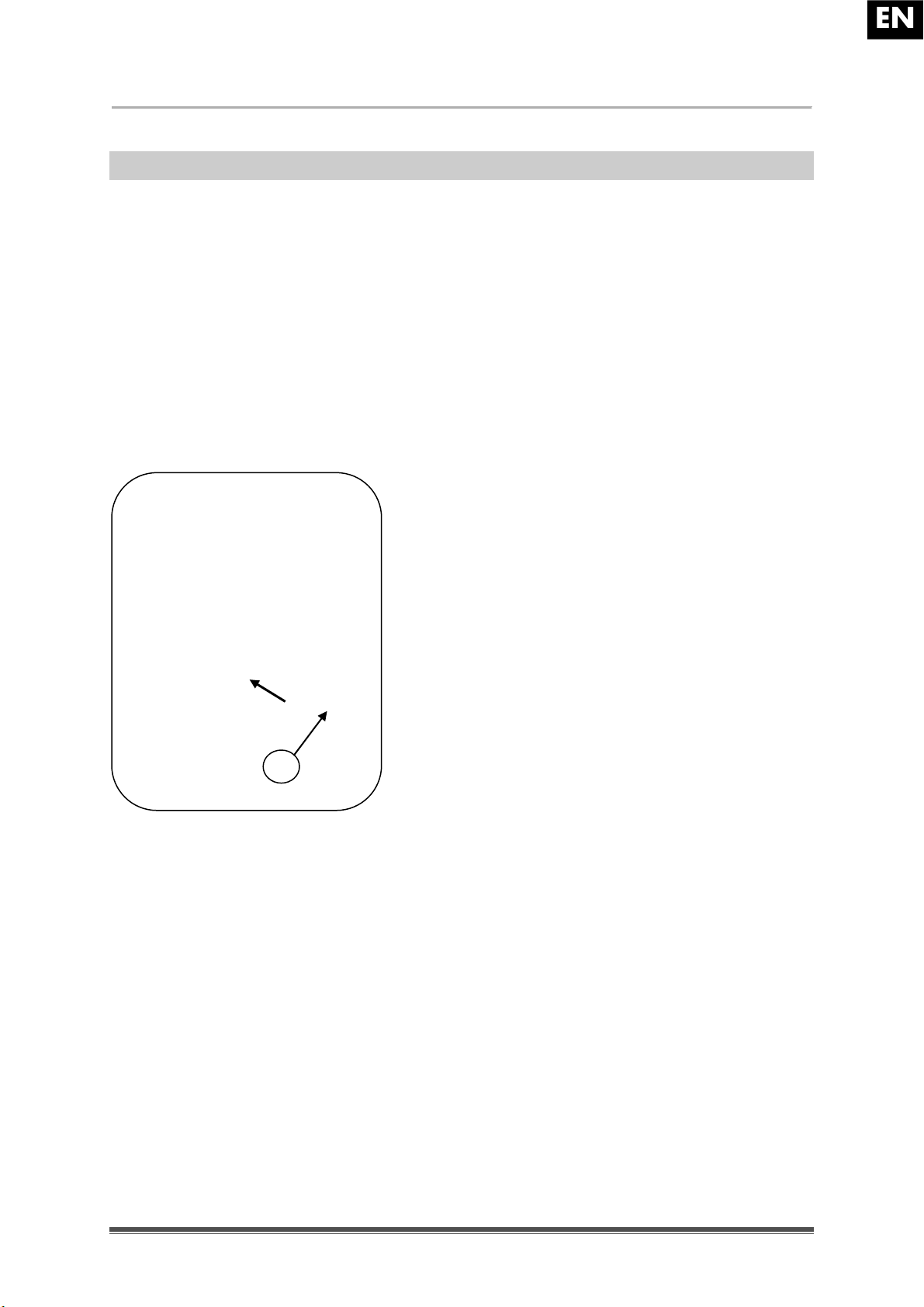
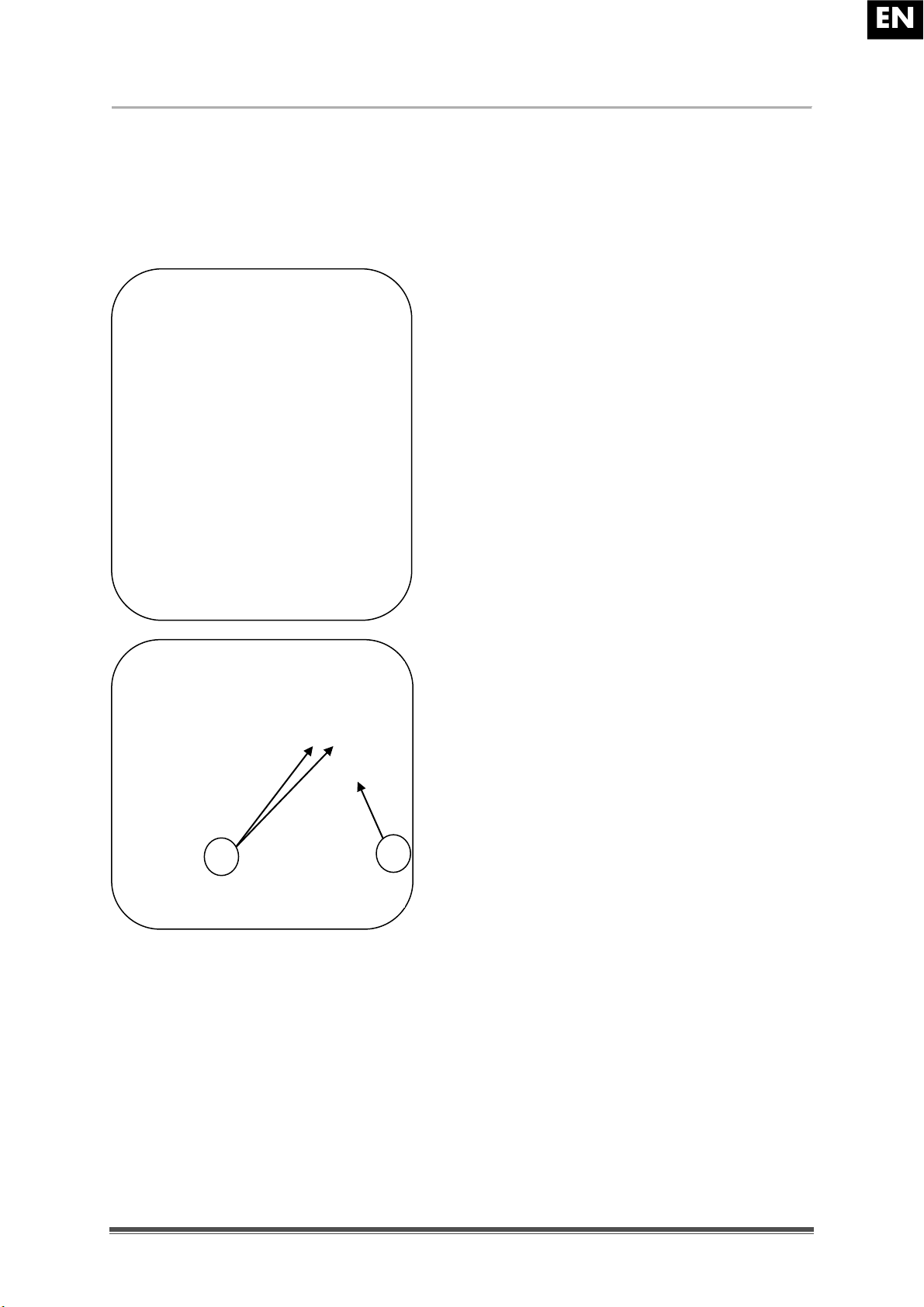
2.2 Mounting the rear wheels
1. Take the rear wheel and push on button .
2. Keep the button pushed in and mount the rear
wheels axle till it stops.
3. Release the button.
4. Check that the wheels is secured.
2.3 Unfolding the wheelchair
L CAUTION: Risk of clamping ! Keep fingers away from moving parts of the
wheelchair.
1. Position yourself behind the wheelchair.
2. Use the hand-grips to open the wheelchair as much as possible.
3. Position yourself at the front of the wheelchair.
4. Push both seating tubes down till they are fixed in their position.
1
Page 10

EN
V200
2010-11
Page%8%
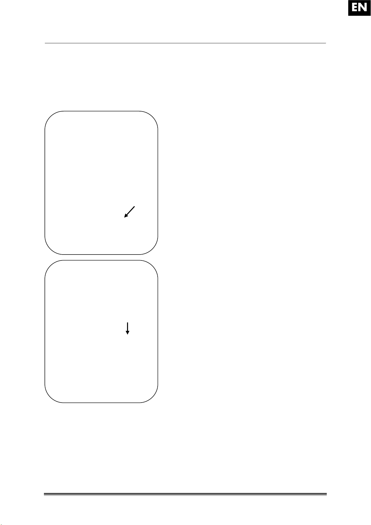
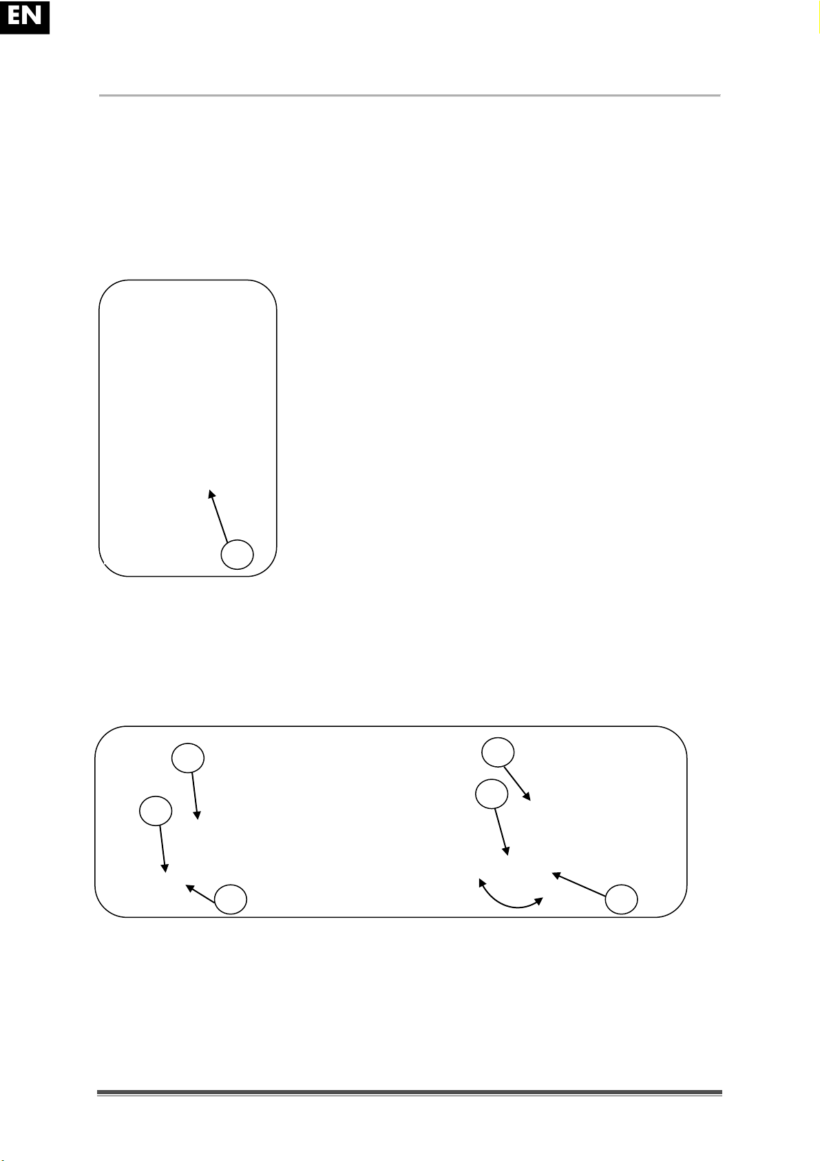
2.4 Mounting or removing of the footrests
The mounting of the footrests is done as follows:
1. Hold the footrest sideways at the outside of the
wheelchairs frame and mount the tube hood
into
the frame.
2. Swing the footrest inwards till it clicks in position.
3. Swing the foot plate downwards.
To take off the footrests:
1. Pull handle
.
2. Swing the footrest to the outside of the wheelchair till
it comes loose from the guidance.
3. Pull the footrest from tube hood
.
2.5 Operating the brakes
L WARNING:
The brakes aren't used to slow down the wheelchair during
movements ! Use the brake only to prevent the wheelchair from unintended
movements.
L WARNING: Good operation of the brakes is influenced by wear and
"#$%&'($&%(#$)#*)%+,)%(-,.)/0&%,-1)#(21)'341)56)! Check the condition of the tires
before each use.
L WARNING: The brakes are adjustable and can wear ! Check the operation of the
brakes before each use.
To apply the brakes:
1. Push the brake handles forward till you feel a distinctive click.
L CAUTION: Risk of unintended movement ! Make sure the wheelchair is on a flat
horizontal surface before releasing the brakes. Never release both brakes
simultaneously.
To release the brakes:
1. Release one brake by pulling the handle backwards.
2. Hold the hand-rim of the release wheel with your hand.
3. Release the second brake by pulling the handle backwards.
Page 11
EN
V200
2010-11
Page%9%
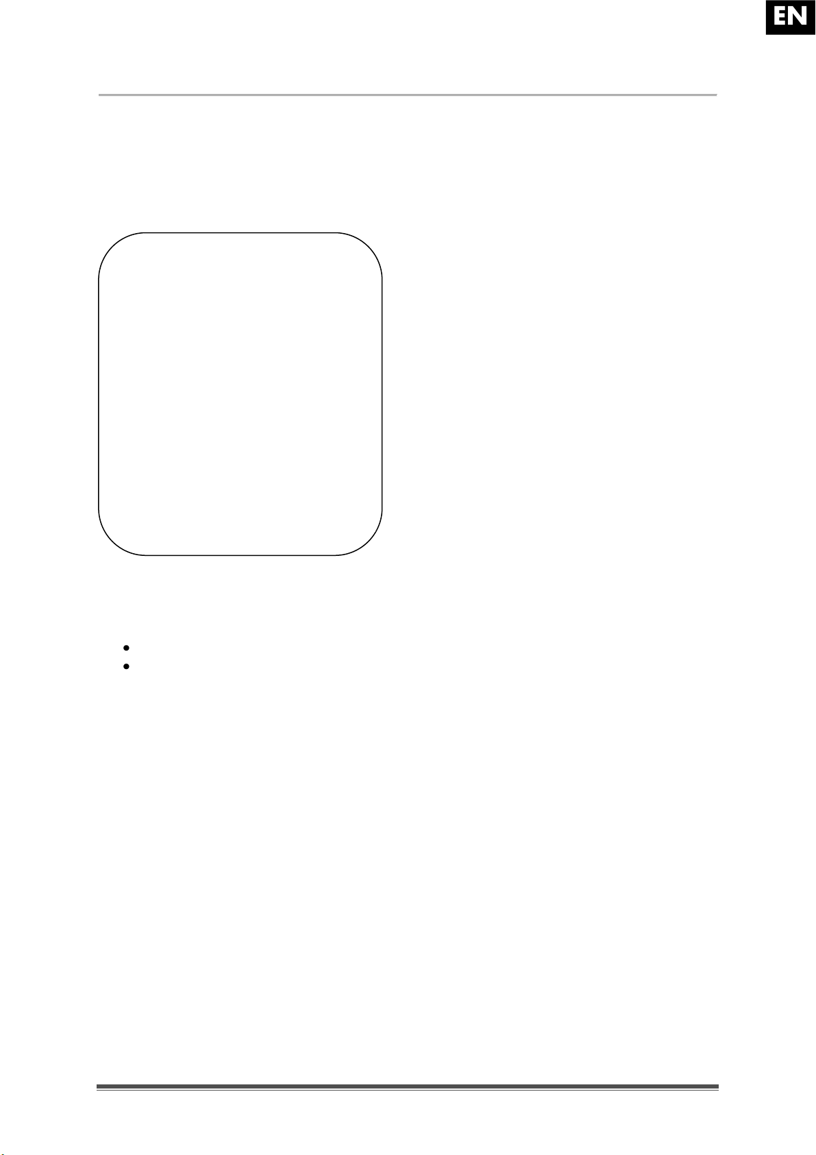
2.6 Mounting or removing of arm supports
The arm supports of the wheelchair can be fold away or taken off.
L CAUTION: Risk of clamping ! Keep fingers, buckles and clothes away from the
bottom side of the arm support.
1. Mount the rear tube of the arm rest in tube
hood
.
2. Make sure the arm support clicks in the
locking mechanism.
3. Fold the arm rest forward.
4. Click the front tube of the arm rest in tube
hood
.
Page 12

EN
V200
2010-11
Page%10%
To open and remove the arm rest:
1. Press lever
and pull the front of the arm rest
upwards.
2. Fold the arm rest backwards.
3. To remove the arm rest, press button
and pull the rear of the arm support from
tube hood .
Page 13
EN
V200
2010-11
Page%11%
2.7 Transfer in and out the wheelchair
L CAUTION: In case you can't perform the transfer in a safe manner, ask someone
to assist you.
L CAUTION: Risk of tipping over of the wheelchair ! Don't stand on the foot plates.
1. Position the wheelchair as close as
possible to the chair, couch or bed to/from
you wish to transfer.
2. Check both brakes from the wheelchair
are in the on position.
3. Fold the foot plates upwards to prevent
standing on them.
4. If the transfer is on the side of the
wheelchair, fold the arm support on that
side upwards. (see § 2.6)
5. Transfer to/from the wheelchair.
2.8 Correct position in the wheelchair
Some recommendations for a comfortable use of the wheelchair:
Position your backside as close as possible to the back rest.
Make sure your upper legs are horizontal – If needed adjust the length of the foot
rests. (see § 3.6)
2.9 Riding the wheelchair
L WARNING: Risk of clamping ! Prevent your fingers from being caught by the
wheels spokes.
L WARNING: Risk of clamping ! Be careful passing through restricted passages
(e.g. doors).
L WARNING: Risk of burns ! Be careful when driving in hot or cold environments
(sunshine, extreme cold, saunas, etc.) for a sufficient amount of time and when
touching - Surfaces can assume the environment temperatures.
1. Release the brakes.
2. Take both hand rims at their highest position.
3. Lean forward and push the hand rims forward until straight arms.
4. Swing your arms loosely back to the hand rims topside and repeat the movement.
Page 14

EN
V200
2010-11
Page%12%
2.10 Moving on slopes
L WARNING: Control your speed ! Moving on slopes as slow as possible.
L WARNING: Consider the capacities of your attendant ! If your attendant doesn't
have enough force to control the wheelchair, put on the brakes.
L WARNING: Risk of tipping over ! Lean forward to move your centre of gravity
forward. To improve a better stability.
1. If available on the wheelchair, wear the safety belt.
2. Do not attempt moving on too high slopes. The maximum
slope angles (upwards and downwards) are mentioned in
table 1.
3. Ask an attendant to help you moving on the slope.
4. Lean forward to move your centre of gravity forward.
2.11 Negotiating steps or kerbs
2.11.1 Getting down steps or kerbs
Riding down low kerbs can be done moving forwards. Make sure that the foot rests don't
touch the ground.
A practiced user can negotiate small steps or kerbs by himself:
L WARNING: Risk of tipping over ! If you don't have
enough experience with your wheelchair, ask
assistance of an attendant.
1. Bring balance on the rear wheels to reduce the pressure
on the front wheels.
2. Negotiate the kerbs.
Higher kerbs can be taken forward with an attendant:
1. Ask the attendant to tip the wheelchair slightly backwards.
2. Get past the kerbs while moving on the rear wheels.
3. Put the wheelchair back on the four wheels.
Page 15

EN
V200
2010-11
Page%13%
An experienced user can negotiate higher kerbs by himself. This
is best done backwards.
1. Turn the wheelchair to have the rear wheels facing the
kerb.
2. Lean forward to move your centre of gravity forward.
3. Move the wheelchair close to the kerbs.
4. Use the hand rim to roll-off wheelchair from the kerb
in a controlled manner.
2.11.2 Moving up steps or kerbs
Moving up steps or kerbs with attendant as follows:
1. Prevent the foot rests from touching the kerb.
2. Ask the attendant to tip the wheelchair backwards, just
enough to move the front wheels over the kerb.
3. Lean backwards to move your centre of gravity above
the rear wheel.
4. Place the front wheels on the kerb.
5. Roll rear wheels of the wheelchair over the kerb.
Higher kerbs are negotiated backwards:
1. Turn the wheelchair to have the rear wheels facing the kerb.
2. Lean backwards and move your centre of gravity above the rear wheels.
3. Ask the attendant to pull the wheelchair on the kerb.
4. Take back the normal position in the wheelchair.
Page 16

EN
V200
2010-11
Page%14%
An experienced user can negotiate kerbs by himself:
L W AR N I N G: Risk of tipping over ! If you haven't enough experience to control the
wheelchair, get help from an attendant.
1. Drive until the kerbs.
2. Ensure that the footrest don't touch the kerbs.
3. Lean backwards so you are balancing on the rear
wheels.
4. Role the frontwheels balancing over the kerbs.
5. Bend forwards for more stability.
6. Role the rear wheels over the kerbs.
2.11.3 Taking of stairs
Taking of stairs while you staying in the wheelchair shall be according following rules:
L WARNING: Risk of tipping over ! Taking of stairs shall always with 2 attendants.
1. Remove the footrests.
2. One attendant tip the wheelchair slightly backwards.
3. The second attendant take the front of the frame.
4. Stay calm, avoid sudden movements and keep your arms inside the wheelchair.
5. Take the steps on the rear wheels of the wheelchair.
6. Mounting the footrests back after taking the stair.
Page 17

EN
V200
2010-11
Page%15%
2.12 Fold up the wheelchair
L CAUTION: Chance of pinching ! Don't place fingers between the components of
the wheelchair.
1.
Fold or remove the footplates (see § 2.4).
2. Take the seat on the front side and backside and pull it up.
2.13 Taking off the wheels
To facilitate the transport off the wheelchair the rear
wheels can be taken off:
1. Make sure the brakes standing in the off
position.
2. Take the wheelchair to the side frame where you
want to remove the wheel.
3. Press the button
in the center of the wheel
hub.
4. Pull the wheel away from the frame.
2.14 Transport in the car
L WARNING: Risk of injury ! See that the wheelchair is attached properly. So you
can avoid injury from the passengers during collision or sudden braking.
L WARNING: Risk of injury ! Use for attaching the wheelchair and passenger
NEVER the same seatbelt.
1. Remove footrests and accessories.
2. Store footrests and accessories safely.
3. If possible, fold the wheelchair and remove the wheels.
4. Place the wheelchair in the luggage place.
5. If the wheelchair and the passenger compartment is NOT separated, attach the
frame of the wheelchair securely to the vehicle. You can use the available safety
belts in the vehicle .
1
Page 18
EN
V200
2010-11
Page%16%
2.15 Use of the wheelchair as seat in a motor vehicle
L WARNING: The wheelchair has passed the crash of ISO 7176-19: 2008 and, as
such, has been designed and tested for use only as forward-facing seat in a
motor vehicle.
L WARNING: The wheelchair's pelvic belt alone is not suited as an occupant
restraint belt.
The wheelchair is tested using the four-point strap-tie system and a 3-point occupantrestraint system.
Whenever feasable, use the seat of the vehicle and store the wheelchair in the cargo area.
Steps to secure the wheelchair in a motor vehicle:
1. Check that the vehicle is equipped with a suitable wheelchair tie down and occupantrestraint system, conform ISO 10542.
2. Check that the components of the wheelchair tie down and occupant restraint system
are not frayed, contaminated, damaged or broken.
3. If equipped with an adjustable seat and/or back tilt, make sure that the wheelchair
user is sitting as upright as possible. If the user's condition prevents this, a risk
assessment should be done to evaluate the user's safety during transit.
4. Remove all mounted accessories such as trays and respiratory equipment, and
secure them in a safe place.
5. Position the wheelchair facing forward in the travelling direction, centrally between
the tie-down rails mounted in the floor of the vehicle.
6. Make sure that the indicated zones around the wheelchair user are clear from rigid
vehicle parts.
Page 19
EN
V200
2010-11
Page%17%
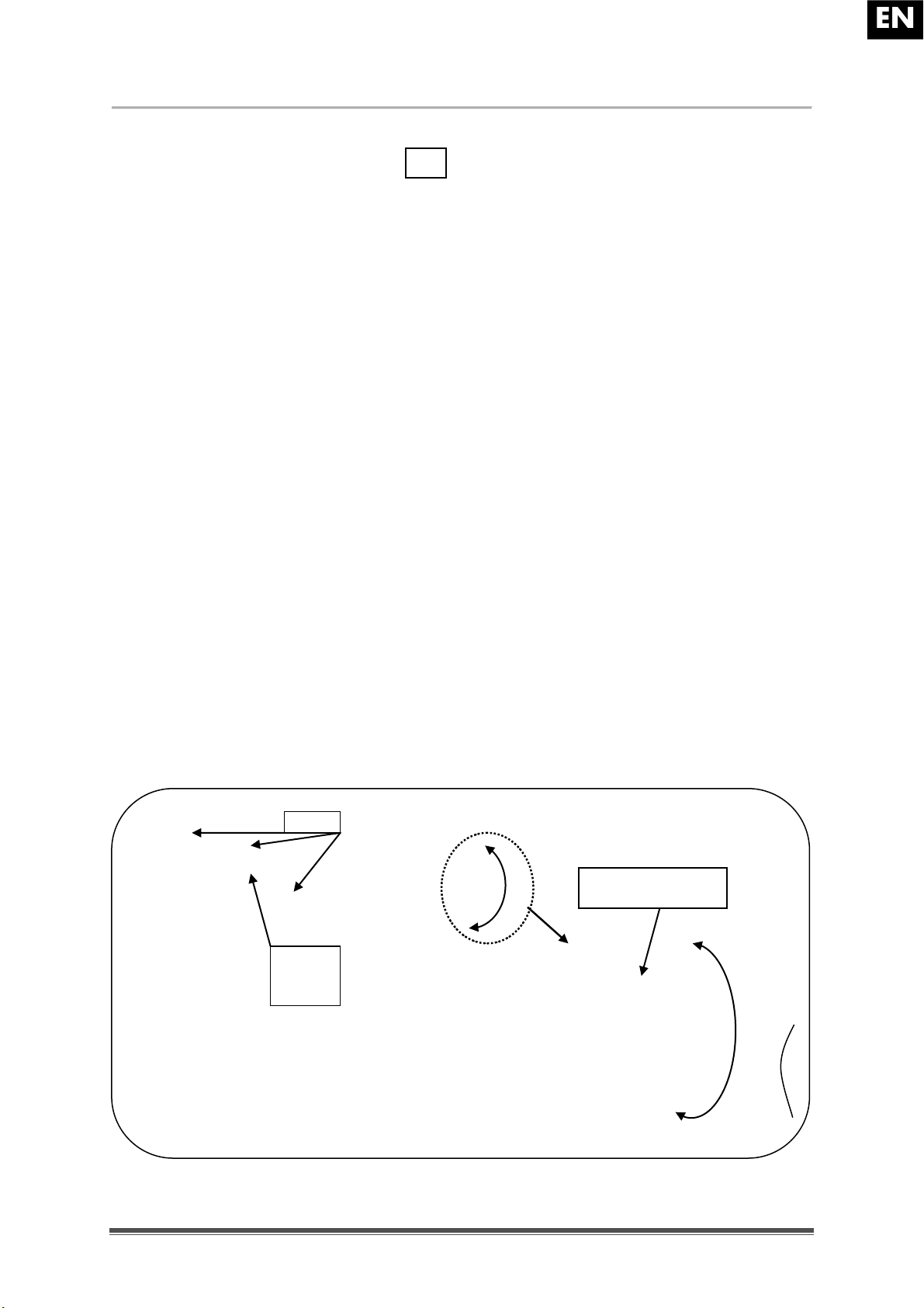
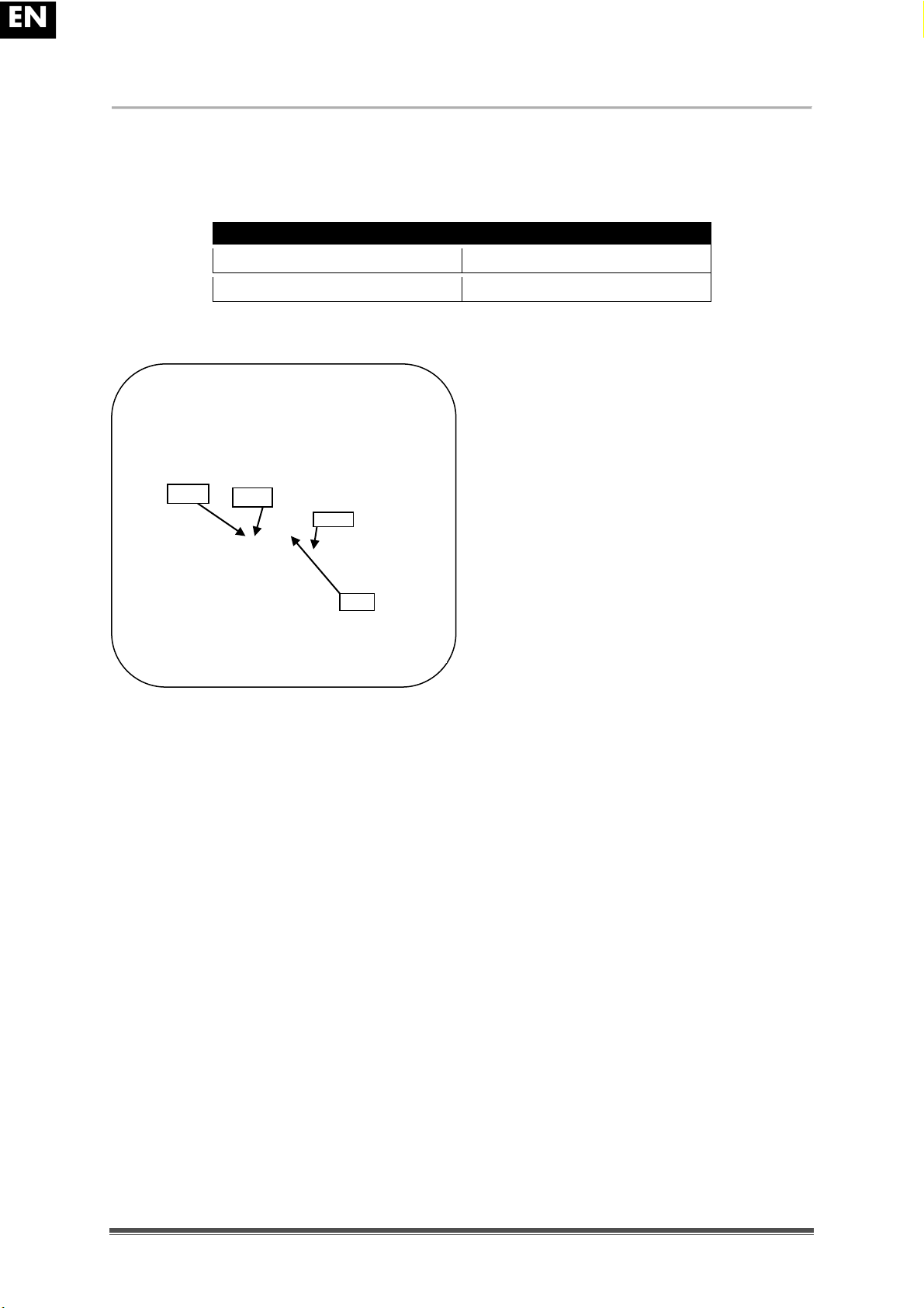
7. Mount the front securement straps according to the instructions of the strap-system
manufacturer at the indicated place. (figure 3)
This place is marked on the wheelchair with a symbol. (figure 4)
8. Roll back the wheelchair until the front straps are tight.
9. Apply the wheelchair brake.
10. Mount the back securement straps according to the instructions of the strap-system
manufacturer at the indicated place. (figure 3)
11. This place is marked on the wheelchair with a symbol. (figure 4)
figure 3
Steps to secure the wheelchair user:
1. Remove both arm rests.
2. If present, attach the wheelchair's pelvic belt.
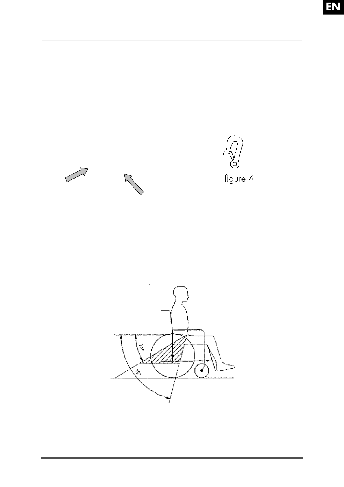
3. Attach the occupant restraint belts according to the instructions of the strap-system
manufacturer.
4. Wear the pelvic belt low across the front of the pelvis, so that the angle of the pelvic
belt is within the preferred zone of 30° to 75° to the horizontal, similar to that shown
below.
Page 20

EN
V200
2010-11
Page%18%
5. A steeper (greater) angle within the preferred zone is desirable.
6. Adjust the belt tightly according to the instructions of the strap-system manufacturer,
consistent with the user's comfort.
7. Ensure that the restraint belt connects in a straight line to the anchor point in the
vehicle and that no bends in the belt are visible, for instance at the axle of the rear
wheel.
8. Install the arm rests, if desired. make sure that belts are not twisted or held away
from the body by wheelchair components such as arm rests or wheels.
3 Installation and adjustment
The instructions in this chapter are for the specialist dealer.
The Vermeiren V200 has been designed to be adjust with a minimum of replacements parts.
There is no need for extra stock of spare parts.
To find a service facility or specialist dealer near you, contact the nearest Vermeiren facility.
A list of Vermeiren facilities can be found on the last page.
L WARNING: Risk of unsafe settings - Use only the settings described in this
manual.
L WARNING: Variation of allowed adjustments can still change the stability of your
wheelchair (tilt back or sideways).
3.1 Tools
To set up the wheelchair the following tools are needed.
Wrench set n° 7 to n° 22
Allen keyset n° 3 to n° 8
Screwdriver n° 4 to n° 5
Screwdriver Phillips head
Page 21

EN
V200
2010-11
Page%19%
3.2 Manner of delivery
The Vermeiren V200 shall be delivered with:
1 frame with arm supports, rear and front wheels (standard delivery
seat height: 500 mm (19.69 in.), seat angle: 5°)
1 pair footrests
Tools
Manual
Accessories
3.3 Adjusting the seat height and seat angle
The Vermeiren V200 is adjustable in 4 seat heights and 5 seat angles (0°-2,5°-5°-10°) by
changing the position of the wheels for each height and angle there is a different setting of
the front and rear wheels.
The summary of the different seat heights by a standard seat angle 5° is tabulated below.
Seat height
Rear wheels
Front wheels
Hole
Position axle plate Ⓓ
Hole
Bushing Ⓑ relative to castor
stem housing Ⓒ
440 mm
(17.32 in.)
Above Above
470 mm
(18.50 in.)
Under Under
500 mm
(19.69 in.)
(Standard)
Under
Under
530 mm
(20.87 in.)
Under Under
Table 2: Seat heights by seat angle 5°
Page 22

EN
V200
2010-11
Page%20%
Front wheel Axle plate rear wheels
Seat height 440 mm (17.32 in.)
Seat height 470 mm (18.50 in.)
Seat height 500 mm (19.69 in.) (standard)
Seat height 530 mm (20.87 in.)
Page 23
EN
V200
2010-11
Page%21%
Change the seat height according the following steps:
1. Remove the rear wheels (see § 2.13).
2. Screw the axle bushings of the rear wheels from the axle plate Ⓓ.
3. Assemble the axle bushings in the right hole of the axle plate, see Table 2 and
previous figure.
4. Check if the axle bushings are fastened well.
5. Screw the swivel axles
Ⓐ of the front wheels loose.
6. Place the front wheels in the right hole of the front fork (table 2).
7. Place the bushings according table 2.
8. Install the swivel axles Ⓐ of the front wheels and tighten them. Check the tension in
the swivel axle Ⓐ so it turn smoothly, but there is no space for motion.
9. Mount the rear wheels.
10. If installed properly the swivel axles of the front wheels and the ground must be
perpendicular. Check this.
11. Adjust the brakes according § 3.5.
For other seat angle and seat height combinations, the above procedure can be used to
adjust the front fork and axle plate in the right combination.
If you don't find the right combination you can always contact the company Vermeiren.
Check that the swivel axles are perpendicular to the ground. If necessary use the procedure
below to adjust the castor stem housing:
1. Loosen the 3 bolts using a size 5 Allen key.
2. Adjust the castor stem housing to the desired angle.
3. Tighten the 3 bolts.
Castor
stem
housing
Indication 5 angle
positions (triangle)
Bolts
Page 24
EN
V200
2010-11
Page%22%
3.4 Adjusting the seat depth
The Vermeiren V200 is adjustable in 2 seat depths by changing the cross.
Seat depth
Cross
440 mm (17.32 in.)
Hole 1 and 3
460 mm (18.11 in.) (Standard)
Hole 2 and 4
Table 3: Seat depth
Change the seat depth according the following
steps:
1. Remove both clips .
2. Move the cross in the desired position
(see table 3).
3. Replace both clips
.
Hole 1
Hole 2
Cross
Page 25
EN
V200
2010-11
Page%23%
3.5 Adjust the brakes
L WARNING: Risk of injury ! Brakes may only be adjusted by your specialist
dealer.
Adjust the brakes according following rules:
1. Install the wheels according § 2.2.
2. Disconnect the brakes by pulling lever
backwards.
3. Loosen the bolts
so the brake
mechanism can slide over the guide
.
4. Pull the brake mechanism over the guide
to the desired position.
5. Retighten the bolts .
6. Check working of the brakes.
7. If necessary repeat the above steps until
the brakes are adjusted well.
2
3
Page 26
EN
V200
2010-11
Page%24%
3.6 Adjusting of the footrests
3.6.1 Length of the footrests
L CAUTION: Risk of damage ! Avoid that the footrests make any contact with the
ground. Keep a minimum distance from 60 mm (2.36 in.) above the ground.
Adjust the length of the footrests as follow:
1. Remove the screw
(on the back of the footrests).
2. Adjust the length of the footrest to a comfortable length.
3. Tighten the screw
properly.
3.6.2 Adjusting the footplates
The footplates can be used in 2 positions. Standard they are adjusted with the base plate in
the back position.
The footplates can be adjusted to the front by switching the left and right footplate.
3.6.3 Adjusting angle foot plates
Adjust the angle of the foot plates as follow:
1. Loosen bolt
.
2. Adjust tube in the desired angle. The angle indication (80°-85°-90°-95°-100°) is
according the dashes .
3. Retighten the bolt
.
1
1
1
2
2
3
3
100°
80°
Page 27
EN
V200
2010-11
Page%25%
3.7 Adjusting the arm support
The arm support of your wheelchair can be adjustable in height and depth. The height of the
arm support can be adjusted in 3 positions.
Height armsupport to seat
Number of the blocks
under the tube
Number of blocks
between tube and
armrests
220 mm (8.66 in.) (Standard)
2
1
230 mm (9.06 in.)
1
2
240 mm (9.45 in.)
0
3
Table 4: Height of arm support
The depth of the armrest can be adjusted in 3 positions.
Depth of the armrest
Used holes
Front position
Back and middle
Middle position (Standard)
Hole 2 and 4
Back position
Front and middle
Table 5: Depth of armrest
Adjust the height and the depth of the armrest as follow:
1. Remove both screws under the armrest.
2. Place the correct number of blocks under and above the tubes, see table 4.
3. Install the armrest with the required holes for depth adjustment.
Page 28

EN
V200
2010-11
Page%26%
4 Maintenance
The expected lifetime of this wheelchair amounts 8 years. Lifetime of the wheelchair is
influenced by its use, storage, regular maintenance, servicing and cleaning.
4.1 Regular Maintenance
The maintenance activities to ensure a good condition for your Vermeiren wheelchair are
described below:
Before every ride
Check the tyres and make them clean. If necessary change the tire.
Check the brakes and adjusted if necessary.
Check the wheelchair (cleanliness, cracks, damage on structural parts ... .)
and make it clean. If necessary change the coating.
Every 8 weeks: inspected and lubricating or adjusting from
Arm supports
Footrests
Brake lever
Wheel axles
Every 6 months or for every new user
General review
Disinfection
Frontwheels, possibly clean bearings
For your convenience, on the back of this manual is a maintenance plan.
Repairing and assembling of spare parts for your wheelchair may only be performed by the
specialist dealer.
Only authorized Vermeiren spare parts may be installed.
4.2 Shipping and storage
The shipping and storage of the wheelchair shall be according following instructions:
Store in a dry place (between +5 °C and +41 °C).
The relative humidity of the air should be between 30% and 70%.
Provide sufficient covering or packaging to protect the wheelchair from rust and
foreign bodies. (e.g. salt water, sea air, sand, dust).
Store all removed parts together in one place (or mark them if necessary) to avoid
mixing up with other products when re-assembling.
Components must be stored without being subjected to strains (Don't put too heavy
parts on the wheelchair, not clamping between something, ...).
Page 29

EN
V200
2010-11
Page%27%
4.3 Care
4.3.1 Covers
The cleaning of the cover shall be according:
Clean covers with a cloth moistened with hot water. Be aware that you don't
soak the cover.
Use a mild commercial detergent for removing stubborn dirt.
Stains can be removed by using a sponge or a soft brush.
Do not use strong cleaning liquids like solvents, nor use hard brushes.
Never clean with steam and/or pressure washers.
4.3.2 Plastic parts
Clean plastic parts of your wheelchair with commercial plastic cleaners. Only use a
soft brush or soft sponge.
Examples of plastic parts are the armrests, footrests, handles, tyres and ... .
4.3.3 Coating
The high quality of the surface layer guarantees optimal protection against corrosion.
If the outer coat is damaged by scratching or in some other way, get your specialist
dealer to repair the affected surface.
When cleaning, only use warm water and normal household detergents and soft
brushes and cloths. Ensure that no wetness gets into the tubes.
Initially the zinc parts only require rubbing with a dry cloth. Stubborn dirt can best be
removed by using a suitable commercial zinc polish.
Page 30

EN
V200
2010-11
Page%28%
4.4 Inspection
In principle we recommend one inspection every year, and a minimum of one before usage
is resumed. All of the following checks must be performed and documented by authorized
persons:
Check the frame parts and the hinged tubes for plastic deformation, cracks and
impaired functioning.
Visually check for damage to the paintwork (danger of corrosion)
Check the operation of the wheels (free running, level rolling, axle play, tyres, profile,
condition of the rims, air pressure in the case of air tyres, floating axles, etc.)
Check the solidity and seating of all screws.
Verify the amount of grease on the metal joints of movable parts
The condition and security of the guides and axles of the steering wheels
Visually check all plastic parts for cracks and brittle spots
Check the functioning of the armrests and leg supports (locking, load, deformation,
wear caused by loads).
Check the operation of other detachable parts (example: anti-tipping device, personal
safety belt, fitting back/seat, etc.)
Completeness of the delivery condition, instruction manual available?
The service must only be signed off in the maintenance plan if a minimum of all the abovementioned aspects have been checked.
Page 31

EN
V200
2010-11
Page%29%
4.5 Disinfection
L WARNING: Dangerous Products - The use of disinfectants is restricted to
authorized personnel.
L WARNING: Dangerous Products, change on irritate your skin - You should wear
suitable protective clothing because the disinfectants could irritate your skin. For
this purpose you should also take note of the product information of the solutions
concerned.
All parts of the wheelchair can be treated by scrubbing with a disinfectant.
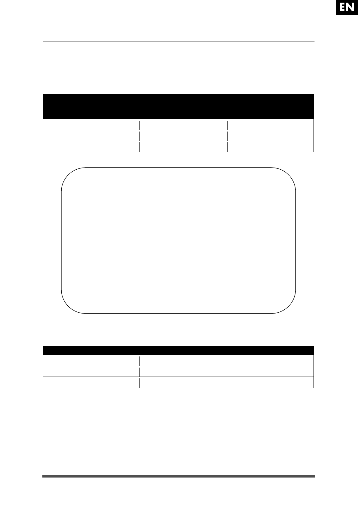
All steps taken to disinfect rehabilitation equipment, their components or other accessory
parts are to be recorded in a disinfection report containing a minimum of the following
information (with product documentation appended):
Date of the
disinfection
Reason
Specification
Substance and
concentration
Signature
Table 6: Example of a disinfection book
Abbreviations used in column 2 (reason):
V = Suspected infection IF = Infection case W = Repetition I = Inspection
For a blank sheet of a disinfection book see § 9.
Page 32

EN
V200
2010-11
Page%30%
The recommended disinfectants for scrubbing (based on the list provided by the Robert
Koch Institute, RKI) are standing in the table below. The current state of the disinfectants
included in the RKI list can be obtained from the Robert Koch Institute (RKI) (homepage:
www.rki.de).
Active substance
Product name
Laundry
disinfection
Surface
disinfection
(scrubbing/wiping
disinfection)
Disinfection of excretions
1 part sputum or stools + 2 parts
diluted solution or 1 part urine + 1 part
diluted solution
Area of
effectiveness
Manufacturer or
Supplier
Sputum
Stools
Urine
Diluted solution
Time to take effect
Diluted solution
Time to take effect
Diluted solution
Time to take effect
Diluted solution
Time to take effect
Diluted solution
Time to take effect
%
Hr. % Hr. % Hr. % Hr. % Hr.
Phenol or phenol
derivative
Amocid 1 12 5 6 5 4 5 6 5 2 A Lysoform
Gevisol
0,5
12 5 4 5 4 5 6 5 2 A Schülke & Mayr
Helipur 6 4 6 4 6 6 6 2 A B. Braun
m-cresylic soap
solution (DAB
6)
1
12 5 4 A
Phenol 1 12 3 2 A
Chlorine, organic
or inorganic
substances with
active chlorine
Chloramin-T
DAB 9
1,5
12
2,5 2 5 4 A1B
Clorina
1, 5
12
2,5 2 5 4 A1B
Lysoform
Trichlorol
2
12 3 2 6 4
A1B
Lysoform
Per combinations
Apesin AP1002
4 4 AB
Tana
PROFESSIONAL
Dismozon pur2
4 1 AB
Bode Chemie
Perform2 3 4
AB
Schülke & Mayr
Wofesteril2
2 4 AB
Kesla Pharma
Formaldehyde
and/or other
aldehydes or
derivatives
Aldasan 2000
4 4 AB
Lysoform
Antifect FD 10
3 4 AB
Schülke & Mayr
Antiseptica
surface
disinfection 7
3 6 AB
Antiseptica
Apesin AP30
5 4 A
Tana
PROFESSIONAL
Bacillocid
special
6 4 AB
Bode Chemie
Buraton 10F
3 4 AB
Schülke & Mayr
Desomed A
2000
3 6 AB
Desomed
Hospital
disinfectant
cleaner
8 6 AB
Dreiturm
Desomed
Perfekt
7 4 AB*
Desomed
Formaldehydesolution (DAB
10), (formaline)
1,5
12 3 4
AB
Incidin Perfekt
1
12 3 4
AB
Ecolab
Incidin Plus
8 6 A
Ecolab
Kohrsolin
2
12 3 4
AB
Bode Chemie
Page 33

EN
V200
2010-11
Page%31%
Active substance
Product name
Laundry
disinfection
Surface
disinfection
(scrubbing/wiping
disinfection)
Disinfection of excretions
1 part sputum or stools + 2 parts
diluted solution or 1 part urine + 1 part
diluted solution
Area of
effectiveness
Manufacturer or
Supplier
Sputum
Stools
Urine
Diluted solution
Time to take effect
Diluted solution
Time to take effect
Diluted solution
Time to take effect
Diluted solution
Time to take effect
Diluted solution
Time to take effect
%
Hr. % Hr. % Hr. % Hr. % Hr.
Formaldehyde
and/or other
aldehydes or
derivatives
Lysoform
4
12 5 6
AB
Lysoform
Lysoformin
3
12 5 6
AB
Lysoform
Lysoformin
2000
4 6 AB
Lysoform
Melsept 2 12 4 6
AB
B. Braun
Melsitt 4 12
10 4 AB
B. Braun
Minutil 2 12 6 4
AB
Ecolab
Multidor 3 6
AB
Ecolab
Nûscosept
5 4
AB
Dr. Nüsken
Chemie
Optisept 7 4
AB*
Dr. Schumacher
Pursept-FD
7 4 AB*
Merz
Ultrasol F
3
12 5 4
AB
Fresenius Kabi
Amphoteric
surfactants
(amfotensiden)
Tensodur 103
2
12 A MFH Marienfelde
Lye
Lime-milk3
20 6 A3B
1 Not effective against myco-bacteria when service disinfecting, especially in the presence of blood.
2 Not suitable for disinfecting blood-contaminated or porous surfaces (e.g. raw wood).
3 Useless for tuberculosis; preparation of Lime-milk: 1 part dissolved lime (calcium hydroxide) + 3 parts water.
* Checked for effectiveness on viruses in accordance with checking methods of the RKI (Federal Health Reporting 38 (1995) 242).
A: Suitable for killing vegetative bacterial germs including myco-bacteria as well as fungi, including fungal spores.
B: Suitable for deactivating viruses.
Table 7: Disinfectants
Kindly consult your specialist dealer if you have queries on matters related to disinfection; he
will gladly assist you.
Page 34

EN
V200
2010-11
Page%32%
5 Guarantee
Excerpt from the "General Business Conditions":
(...)
5. The guarantee period for warranty claims is 24 months. As a result of our superior quality
requirements, we can increase the time bar on warranty claims beyond these fundamental,
statutory requirements for
(...)
-Frame and cross-hinge of wheelchairs 4 years
The guarantee excludes damage arising from structural changes to our products, insufficient
maintenance, defective or improper handling or storage or the use of non-original parts.
Likewise, the guarantee excludes parts or working parts subject to natural wear and tear.
(...)
6 Disposal
When disposing of the wheelchair, contact your local disposal centre or return the product to
your specialist dealer who, after submitting it to a hygienic procedure, will be able to send it
back to the manufacturer who will dispose of and recycle it correctly, separating it into its
component materials.
Packaging materials can be taken to disposal or recycling centers or to your specialist
dealer.
Page 35

EN
V200
2010-11
Page%33%
7 Declaration of conformity
Page 36

EN
V200
2010-11
Page%34%
8 Maintenance plan
Date
Maintenance
Remarks
Paraph
1/1/2010
Greasing and general servicing
non
Page 37

EN
V200
2010-11
Page%35%
9 Disinfection book
Date of the
disinfection
Reason
Specification
Substance and
concentration
Signature
Abbreviations used in column 2 (reason):
V = Suspected infection IF = Infection case W = Repetition I = Inspection
Page 38

EN
V200
2010-11
Page%36%
SERVICE
The wheelchair was serviced:
Le fauteuil roulant contrôlé:
De rolstoel is gecontroleerd:
Das Rollstuhl wurde überprüft:
Il sedia a rotelle è stat ispezionata:
La silla de ruedas ha sido revisado:
Dealer´s)stamp)•)Cachet)du)revendeur)•)Stempel)van)de)handelaar
Händlerstempel)•)Timbro)del)rivenditore)•)Sello)del)distribuidor:
Date)•)Datum)•)Data)•)Fecha:
Dealer´s)stamp)•)Cachet)du)revendeur)•)Stempel)van)de)handelaar
Händlerstempel)•)Timbro)del)rivenditore)•)Sello)del)distribuidor:
Date)•)Datum)•)Data)•)Fecha:
Dealer´s)stamp)•)Cachet)du)revendeur)•)Stempel)van)de)handelaar
Händlerstempel)•)Timbro)del)rivenditore)•)Sello)del)distribuidor:
Date)•)Datum)•)Data)•)Fecha:
Dealer´s)stamp)•)Cachet)du)revendeur)•)Stempel)van)de)handelaar
Händlerstempel)•)Timbro)del)rivenditore)•)Sello)del)distribuidor:
Date)•)Datum)•)Data)•)Fecha:
Dealer´s)stamp)•)Cachet)du)revendeur)•)Stempel)van)de)handelaar
Händlerstempel)•)Timbro)del)rivenditore)•)Sello)del)distribuidor:
Date)•)Datum)•)Data)•)Fecha:
Dealer´s)stamp)•)Cachet)du)revendeur)•)Stempel)van)de)handelaar
Händlerstempel)•)Timbro)del)rivenditore)•)Sello)del)distribuidor:
Date)•)Datum)•)Data)•)Fecha:
Dealer´s)stamp)•)Cachet)du)revendeur)•)Stempel)van)de)handelaar
Händlerstempel)•)Timbro)del)rivenditore)•)Sello)del)distribuidor:
Date)•)Datum)•)Data)•)Fecha:
Dealer´s)stamp)•)Cachet)du)revendeur)•)Stempel)van)de)handelaar
Händlerstempel)•)Timbro)del)rivenditore)•)Sello)del)distribuidor:
Date)•)Datum)•)Data)•)Fecha:
Dealer´s)stamp)•)Cachet)du)revendeur)•)Stempel)van)de)handelaar
Händlerstempel)•)Timbro)del)rivenditore)•)Sello)del)distribuidor:
Date)•)Datum)•)Data)•)Fecha:
Dealer´s)stamp)•)Cachet)du)revendeur)•)Stempel)van)de)handelaar
Händlerstempel)•)Timbro)del)rivenditore)•)Sello)del)distribuidor:
Date)•)Datum)•)Data)•)Fecha:
For service checklists an additional technical information, please see our specialist dealers nearest to you.
More information on our website at: www.vermeiren.com.
Les listes des contrôles à effectuer lors des entretiens de même que toute autre information technique sont
disponibles auprès de nos filiales. Pour de plus amples informations, consultez le site: www.vermeiren.fr.
Servicelijsten en andere technische informatie kunt u aanvragen bij onze vestigingen. Meer informatie vindt
u ook op: www.vermeiren.be.
Servicechecklisten und weitere technische Informationen erhalten Sie über unsere Niederlassungen.
Informationen unter: www.vermeiren.de, www.vermeiren.at, www.vermeiren.ch.
Gli elenchi di controllo di manutenzione e ulteriori informazioni tecniche sono disponibili presso le nostre
filiali. Per informazioni consultare il sito: www.vermeiren.com.
Page 39

FR
Inst r uctions pour les distrib ute u rs
Ce manuel d'instructions fait partie du produit et doit accompagner chaque fauteuil roulant vendu.
Version : A, Novembre 2010
Tous droits réservés, y compris la traduction.
Aucune partie de ce manuel ne peut être reproduite, sous quelque forme que ce soit (imprimée,
photocopie, microfilm ou tout autre procédé) sans l'autorisation écrite du publicateur, ni traitée,
dupliquée ou distribuée à l'aide de systèmes électroniques.
© N.V. Vermeiren N.V. 2010
Page 40

FR
V200
2010-11
Page%1%
Table des matières
Préface .. .. . .. . . .. . . .. . . .. . . .. . . .. . . .. . . .. . . . . . .. . . .. . . .. . . .. . . .. . . .. . . .. . . .. . .. . . .. . . .. . . .. . . .. . . .. . . .. . 2!
1! Description du produit . . . .. . . .. . . .. . . .. . . .. . . .. . .. . . .. . . .. . . .. . . .. . . .. . . .. . . .. . . . . . 3!
1.1! Utilisation prévue ........................................................................................................ 3!
1.2! Caractéristiques techniques ......................................................................................... 4!
1.3! Schéma ........................................................................................................................ 5!
1.4! Accessoires .................................................................................................................. 6!
1.5! Emplacement de la plaque d'identification ................................................................. 6!
1.6! Explication des symboles ............................................................................................ 6!
2! Utilisation ... . . .. . . .. . . .. . . .. . . . . . .. . . .. . . .. . . .. . . .. . . .. . . .. . .. . . .. . . .. . . .. . . .. . . .. . . .. . . .. . . 7!
2.1! Transport du fauteuil roulant ....................................................................................... 7!
2.2! Montage des roues arrière ........................................................................................... 7!
2.3! Dépliage du fauteuil roulant ........................................................................................ 7!
2.4! Montage ou retrait des repose-pieds............................................................................ 8!
2.5! Actionnement des freins .............................................................................................. 8!
2.6! Montage ou retrait des repose-bras ............................................................................. 9!
2.7! Transfert dans et hors du fauteuil roulant .................................................................. 11!
2.8! Position correcte du fauteuil roulant ......................................................................... 11!
2.9! Déplacements avec le fauteuil roulant ...................................................................... 11!
2.10! Déplacements en pente .............................................................................................. 12!
2.11! Passage de marches ou de bordures de trottoirs ........................................................ 12!
2.12! Pliage du fauteuil roulant .......................................................................................... 15!
2.13! Retrait des roues ........................................................................................................ 15!
2.14! Transport en voiture .................................................................................................. 15!
2.15! Utilisation du fauteuil roulant comme siège dans un véhicule.................................. 16!
3! Installation et réglage . . .. . . .. . . . . . .. . . .. . . .. . . .. . . .. . . .. . . .. . . .. . .. . . .. . . .. . . .. . . . 18!
3.1! Outils ......................................................................................................................... 18!
3.2! Mode de livraison ...................................................................................................... 19!
3.3! Réglage de la hauteur du siège et de l'angle du siège ............................................... 19!
3.4! Réglage de la profondeur du siège ............................................................................ 22!
3.5! Réglez les freins ........................................................................................................ 23!
3.6! Réglage des repose-pieds .......................................................................................... 24!
3.7! Réglage du repose-bras ............................................................................................. 25!
4! Maintenance ... . . .. . . .. . . . . . .. . . .. . . .. . . .. . . .. . . .. . . . . . .. . . .. . . .. . . .. . . .. . . .. . . .. . . . . . .. 26!
4.1! Maintenance régulière ............................................................................................... 26!
4.2! Expedition et stockage .............................................................................................. 26!
4.3! Entretien .................................................................................................................... 27!
4.4! Inspection .................................................................................................................. 28!
4.5! Désinfection .............................................................................................................. 29!
5! Garantie . . .. . . .. . . .. . . .. . .. . . .. . . .. . . .. . . .. . . .. . . .. . . .. . .. . . .. . . .. . . .. . . .. . . .. . . .. . . .. . . . . . 32!
6! Mise au rebut .. . .. . . .. . . .. . . .. . . .. . . .. . .. . . .. . . .. . . .. . . .. . . .. . . .. . . . . . .. . . .. . . .. . . .. . . .. 32!
7! Déclaration de conformité . .. . . .. . . .. . . .. . . . . . .. . . .. . . .. . . .. . . .. . . .. . . .. . .. . . .. 33!
8! Plan de maintenance .. .. . . .. . . .. . . .. . . .. . . .. . . . . . .. . . .. . . .. . . .. . . .. . . .. . . .. . . .. . .. . 34!
9! Journal de désinfection . . . . . .. . . .. . . .. . . .. . . .. . . .. . . . . . .. . . .. . . .. . . .. . . .. . . .. . . .. 35!
Page 41

FR
V200
2010-11
Page%2%
Préface
Nous tenons tout d'abord à vous remercier de nous avoir fait confiance en choisissant l'un
de nos fauteuils roulants.
Les fauteuils roulants Vermeiren sont le résultat de nombreuses années de recherche et
d'expérience. Au cours du développement, une attention spéciale a été portée sur la facilité
d'utilisation et les possibilités d'entretien du fauteuil roulant.
La durée de vie attendue de 8 ans de votre fauteuil roulant est fortement influencée par
l'entretien et la maintenance dont il bénéficie.
Ce manuel vous aidera à connaître le fonctionnement de votre fauteuil roulant.
Le respect des instructions d'utilisation et des instructions de maintenance est une condition
essentielle de la garantie.
Ce manuel reflète les derniers développements du produit. Vermeiren est autorisé à
apporter des modifications sans devoir pour autant adapter ou remplacer les modèles
fournis précédemment.
Pour toute question, consultez votre distributeur.
Page 42

FR
V200
2010-11
Page%3%
1 Description du produit
1.1 Utilisation prévue
Le fauteuil roulant est destiné aux personnes qui ont des difficultés à marcher ou sont dans
l'impossibilité de marcher.
Le fauteuil roulant est destiné au transport d'une seule personne.
Le fauteuil roulant est destiné à une utilisation en intérieur et en extérieur.
L'utilisateur peut lui-même faire avant le fauteuil roulant ou se faire pousser par une autre
personne.
Les différents types d'équipements et d'accessoires et la construction modulaire permettent
une utilisation complète par des personnes souffrant des handicaps suivants :
paralysie,
perte des membres (amputation de jambe),
déficiences ou déformations des membres,
articulations raides ou abîmées,
insuffisances cardiaques et mauvaise circulation sanguine,
troubles de l'équilibre,
cachexie (perte musculaire),
ainsi que par des personnes âgées.
En cas de fourniture pour des besoins individuels :
la taille et le poids (maximum 130 kg),
l'état physique et psychologique,
la nature de la résidence,
l'environnement
doivent être pris en considération.
Votre fauteuil roulant ne doit être utilisé que sur des surfaces où les quatre roues touchent le
sol et où le contact est suffisant pour entraîner les roues de manière équilibrée.
Il est recommandé de s'entraîner à un usage sur des surfaces irrégulières (pavés, etc.),
pentes, courbes et à passer des obstacles (bordures de trottoirs, etc.).
Le fauteuil roulant ne doit pas être utilisé comme échelle, ni pour le transport d'objets lourds
ou chauds.
En cas d'utilisation sur des paillassons, moquettes ou revêtements de sols non fixés, le
revêtement de sol peut être endommagé.
Utilisez uniquement des accessoires approuvés par Vermeiren.
Le fabricant n'est pas responsable des dommages causés par l'absence ou l'inadéquation
de l'entretien, ou par le non-respect des instructions de ce manuel.
Le respect des instructions d'utilisation et de maintenance est une condition essentielle de la
garantie.
Page 43

FR
V200
2010-11
Page%4%
1.2 Caractéristiques techniques
Les indications techniques ci-dessous sont valides pour le fauteuil roulant avec ses réglages
standard.
En cas d'utilisation d'autres repose-pieds / repose-bras ou autres accessoires, les valeurs
indiquées sont modifiées.
Marque
Vermeiren
Adresse
Vermeirenplein 1/15, B-2920 Kalmthout
Type
Fauteuil roulant manuel
Modèle
V200
Masse maximale de l'occupant
130 kg
Description
Minimum
Maximum
Longueur totale avec repose-jambe
1010 mm
Largeur d'assise efficace
390 mm
420 mm
440 mm
460 mm
480 mm
500 mm
Largeur totale (en fonction de la largeur d'assise)
590 mm
620 mm
640 mm
660 mm
680 mm
700 mm
Longueur plié
1000 mm
Largeur plié
320 mm
Hauteur plié
955 mm
Masse totale
16,5 kg
Masse de la partie la plus lourde
9 kg
Stabilité statique en descente
10° (en configuration standard)
Stabilité statique en montée
7° (en configuration standard)
Stabilité statique latérale
18° (en configuration standard)
Passage d'obstacle
60 mm
Angle du plan d'assise
0°
10°
Profondeur d'assise efficace
440 mm
460 mm
Hauteur de la surface d'assise sur le bord avant
440 mm
530 mm
Angle du dossier
90°
Hauteur du dossier
400 mm
Distance entre le repose-pieds et le siège
430 mm
Angle entre le repose-pieds et le siège
8°
Distance entre l'accoudoir et le siège
220 mm
240 mm
Emplacement avant de la structure des accoudoirs
410 mm
Diamètre de la main-courante
535 mm
Emplacement horizontal de l'essieu (flèche)
50 mm
Rayon de braquage minimum
1500 mm
Diamètre des roues arrière Krypton PU
22"
24"
Pression des pneus, roues arrière (motrices)
Maximum 3,5 bar
Diamètre des roues directrices Krypton PU
200 mm
Pression des pneus, roues directrices
Maximum 2,5 bar
Température de stockage et d'utilisation
+ 5 °C
+41 °C
Humidité de stockage et d'utilisation
30%
70%
Nous%nous%réservons%le%droit%d’apporter%des%modifications%techniques.%Tolérance de mesure ± 15 mm / kg / °
Tableau 1 : Caractéristiques techniques
Page 44

FR
V200
2010-11
Page%5%
Le fauteuil roulant respecte les exigences définies dans :
ISO 7176-8 : Exigences et méthodes de test pour les forces statiques, d'impact et de
fatigue.
ISO 7176-16 : Résistance à l'inflammation des pièces rembourrées
ISO 7176-19 : systèmes mobiles à roues destinés à une utilisation comme sièges dans des
véhicules motorisés.
1.3 Schéma
1 = Accoudoirs
2 = Repose-bras
3 = Repose-pieds
4 = Freins
5 = Roues directrices (roues avant)
6 = Roues motrices (roues arrière)
7 = Siège
8 = Dossier
9 = Patte d'inclinaison
10 = Traverse
11 = Poignées
Page 45

FR
V200
2010-11
Page%6%
1.4 Accessoires
Les accessoires suivants sont disponibles pour le V200 :
Sangle pelvienne antérieure (B20) à monter sur les tubes du dossier (voir le manuel
correspondant)
Système anti-basculement (B78) à monter sur le cadre inférieur (voir le manuel
correspondant)
1.5 Emplacement de la plaque d'identification
1.6 Explication des symboles
Poids maximum
Usage intérieur et extérieur
Descente
Montée
CE conformité
Page 46

FR
V200
2010-11
Page%7%
2 Utilisation
Ce chapitre décrit l'utilisation quotidienne. Ces instructions sont destinées à l'utilisateur
et au distributeur.
Le fauteuil roulant est livré entièrement assemblé par votre distributeur. Les instructions
destinées au distributeur pour le réglage du fauteuil roulant sont indiquées au § 3.
2.1 Transport du fauteuil roulant
Le meilleur moyen de déplacer le fauteuil roulant consiste à le faire rouler sur ses roues.
Si cela n'est pas (par exemple en cas de retrait des roues arrière pour le transport dans une
voiture), saisir fermement le cadre à l'avant et les poignées. Ne pas saisir le fauteuil roulant
par les accoudoirs ni par les repose-pieds.
2.2 Montage des roues arrière
1. Prenez la roue arrière et poussez sur le
bouton
.
2. Maintenez le bouton enfoncé et montez
l'essieu arrière jusqu'à ce qu'il soit bloqué.
3. Relâchez le bouton.
4. Vérifiez que les roues sont bloquées.
2.3 Dépliage du fauteuil roulant
L ATTENTION : risque de pincement, laissez les doigts à l'écart des pièces
mobiles du fauteuil roulant.
1. Placez-vous derrière le fauteuil roulant.
2. Utilisez les poignées pour ouvrir le fauteuil roulant autant que possible.
3. Placez-vous à l'avant du fauteuil roulant.
4. Poussez sur les deux tubes de l'assise vers le bas jusqu'à ce qu'ils soient fixés à leur
place.
1
Page 47

FR
V200
2010-11
Page%8%
2.4 Montage ou retrait des repose-pieds
Procédez de la manière suivante pour le montage des
repose-pieds :
1. Tenez le repose-pied latéralement à l'extérieur du
châssis du fauteuil roulant et montez le logement de
tube
sur le châssis.
2. Basculez le repose-pied vers l'intérieur jusqu'à ce
qu'il se bloque en position.
3. Basculez la plaque repose-pied vers le bas.
Pour retirer les repose-pieds :
1. Tirez sur la poignée
.
2. Basculez le repose-pied vers l'extérieur du fauteuil
roulant jusqu'à ce qu'il ne soit plus fixé au système de
guidage.
3. Tirez le repose-pied hors du logement de tube
.
2.5 Actionnement des freins
L AVERTISSEMENT :
les freins ne servent pas à ralentir le fauteuil roulant en
mouvement. Ne les utilisez que pour empêcher des mouvements non souhaités
du fauteuil roulant.
L AVERTISSEMENT : le bon fonctionnement des freins dépend de l'usure et de
l'état des pneus%(eau,%huile,%boue,%…).%Vérifiez l'état des pneus avant chaque
utilisation.
L AVERTISSEMENT : les freins sont réglables et peuvent s'user. Contrôlez le
fonctionnement des freins avant chaque utilisation.
Pour actionner les freins :
1. Poussez les poignées de freins vers l'avant jusqu'à ce que vous sentiez un clic net.
L ATTENTION : risque de mouvement non souhaité. Vérifiez que le fauteuil roulant
se trouve sur une surface horizontale plane avant de relâcher les freins. Ne
relâchez jamais les deux freins en même temps.
Pour relâcher les freins :
1. Relâchez un frein en tirant une poignée vers l'arrière.
2. Maintenez avec votre main la main-courante de la roue relâchée.
3. Relâchez le deuxième frein en tirant la poignée vers l'arrière.
Page 48

FR
V200
2010-11
Page%9%
2.6 Montage ou retrait des repose-bras
Les repose-bras du fauteuil roulant peuvent être dépliés ou retirés.
L ATTENTION : risque de pincement, laissez les doigts, boucles et vêtements à
l'écart du bas du repose-bras.
1. Montez le tube arrière de l'accoudoir dans le
logement de tube
.
2. Vérifiez que le support de bras se met bien en
place dans le mécanisme de verrouillage.
3. Pliez l'accoudoir vers l'avant.
4. Verrouillez le tube avant de l'accoudoir dans le
logement de tube
.
Page 49

FR
V200
2010-11
Page%10%
Pour ouvrir et retirer l'accoudoir :
1. Appuyez sur le levier
et tirez l'avant de
l'accoudoir vers le haut.
2. Pliez l'accoudoir vers l'arrière.
3. Pour retirer l'accoudoir, appuyez sur le bouton
et tirez l'arrière du repose-bras hors
du logement de tube.
Page 50

FR
V200
2010-11
Page%11%
2.7 Transfert dans et hors du fauteuil roulant
L ATTENTION : si vous ne pouvez pas réaliser le transfert en toute sécurité,
demandez à quelqu'un de vous aider.
L ATTENTION : risque de basculer hors du fauteuil roulant. Ne vous levez pas sur
les plaques repose-pieds.
1. Placez le fauteuil roulant aussi près que
possible de la chaise, du canapé ou du lit
concerné par le transfert.
2. Vérifiez que les deux freins du fauteuil
roulant sont actionnés.
3. Basculez les plaques repose-pieds vers
le haut pour éviter de marcher dessus.
4. Si le transfert est réalisé sur le côté du
fauteuil roulant, rabattez le repose-bras
de ce côté vers le haut (voir § 2.6).
5. Procédez au transfert vers/depuis le
fauteuil roulant.
2.8 Position correcte du fauteuil roulant
Recommandations pour une utilisation confortable du fauteuil roulant :
Placez votre dos aussi proche que possible du dossier.
Assurez-vous que vos cuisses soient horizontales. Réglez la longueur des repose-
pieds si nécessaire (voir § 3.6).
2.9 Déplacements avec le fauteuil roulant
L AVERTISSEMENT : risque de pincement, évitez de laisser vos doigts se prendre
dans les rayons des roues.
L AVERTISSEMENT : risque de pincement, soyez prudent lors de passages dans
des endroits étroits (par exemple les portes).
L AVERTISSEMENT : risque de brûlures – Soyez prudents lorsque vous
conduisez dans des environnements chauds ou froids (soleil, froid extrême,
saunas, etc.) - Les parties métalliques peuvent subir les températures de
l'environnement et devenir très chaudes ou très froides.
1. Relâchez les freins.
2. Saisissez le haut des deux mains-courantes.
3. Penchez-vous en avant et poussez les mains-courantes vers l'avant jusqu'à ce que
vos bras soient tendus.
4. Ramenez doucement vos bras vers le haut des mains-courantes et répétez ce
mouvement.
Page 51

FR
V200
2010-11
Page%12%
2.10 Déplacements en pente
L AVERTISSEMENT : contrôlez votre vitesse, déplacez-vous sur les pentes aussi
lentement que possible.
L AVERTISSEMENT : tenez compte des capacités de votre accompagnateur. S'il
n'a pas assez de force pour contrôler le fauteuil roulant, actionnez les freins.
L AVERTISSEMENT : risque de basculement. Penchez-vous vers l'avant pour
déplacer votre centre de gravité vers l'avant. Vous gagnerez ainsi en stabilité.
1. Si le fauteuil roulant est équipé d'une ceinture de
sécurité, utilisez-la.
2. N'essayez pas de franchir des pentes trop difficiles. Les
angles de pente maximum (montée et descente) sont
indiqués dans le tableau 1.
3. Demandez à un assistant de vous aider à franchir une
pente.
4. Penchez-vous vers l'avant pour déplacer votre centre de
gravité vers l'avant.
2.11 Passage de marches ou de bordures de trottoirs
2.11.1 Descente de marches ou de bordures de trottoirs
Il est possible de descendre de petites bordures de trottoirs en avançant. Assurez-vous que
les repose-pieds ne touchent pas le sol.
Un utilisateur entraîné peut franchir seul de petites marches ou
bordures de trottoirs :
L AVERTISSEMENT : risque de basculement. Si vous
n'êtes pas assez expérimenté avec votre fauteuil
roulant, demandez de l'aide à quelqu'un.
1. Mettez plus de poids sur les roues arrière pour réduire la
pression sur les roues avant.
2. Franchissez les bordures de trottoirs.
Il est possible de franchir des bordures de trottoirs plus hautes avec un assistant :
1. Demandez à l'assistant d'incliner légèrement le fauteuil roulant vers l'arrière.
2. Franchissez les bordures de trottoirs en roulant sur les roues arrière.
3. Reposez le fauteuil roulant sur ses quatre roues.
Page 52

FR
V200
2010-11
Page%13%
Un utilisateur entraîné peut franchir seul des bordures de
trottoirs plus hautes. L'idéal est de les franchir en marche
arrière.
1. Tournez le fauteuil roulant, roues arrière face à la
bordure de trottoir.
2. Penchez-vous vers l'avant pour déplacer votre centre de
gravité vers l'avant.
3. Reculez près de la bordure de trottoir.
4. Utilisez la main-courante pour contrôler la descente de la
bordure de trottoir.
2.11.2 Montée de marches ou de bordures de trottoirs
Montez des marches ou bordures de trottoirs avec un assistant de la manière suivante :
1. Les repose-pieds ne doivent pas toucher la bordure de
trottoir.
2. Demandez à l'assistant d'incliner légèrement le fauteuil
roulant vers l'arrière, juste assez pour placer les roues
avant en haut de la bordure de trottoir.
3. Penchez-vous vers l'arrière pour déplacer votre centre
de gravité au-dessus de la roue arrière.
4. Placez les roues avant sur la bordure de trottoir.
5. Montez la bordure du trottoir avec les roues arrière du
fauteuil roulant.
Franchissez les bordures de trottoirs hautes en marche arrière :
1. Tournez le fauteuil roulant, roues arrière face à la bordure de trottoir.
2. Penchez-vous vers l'arrière et déplacez votre centre de gravité au-dessus de la roue
arrière.
3. Demandez à l'assistant de tirer le fauteuil roulant sur la bordure de trottoir.
4. Reprenez votre position normale dans le fauteuil roulant.
Page 53

FR
V200
2010-11
Page%14%
Un utilisateur entraîné peut franchir seul des bordures de trottoirs.
L AVERTISSEMENT : risque de basc ulement. Si vous n'êtes pas assez expé rimenté
pour contrôle r le fauteuil roulant, demandez de l'aide à quelqu'un.
1. Roulez jusqu'aux bordures de trottoirs.
2. Assurez-vous que les repose-pieds ne touchent pas les
bordures de trottoirs.
3. Penchez-vous vers l'arrière pour déplacer votre centre
de gravité vers les roues arrière.
4. Franchissez la bordure de trottoir avec les roues avant.
5. Penchez-vous vers l'avant pour plus de stabilité.
6. Franchissez la bordure de trottoir avec les roues arrière.
2.11.3 Passage d'escaliers
Le passage d'escaliers en restant sur le fauteuil roulant doit toujours se faire dans le respect
des règles suivantes :
L AVERTISSEMENT : risque de basculement. Toujours passer des escaliers avec
2 assistants.
1. Retirez les repose-pieds.
2. Un assistant incline légèrement le fauteuil roulant vers l'arrière.
3. Le deuxième assistant attrape l'avant du châssis.
4. Restez calme, évitez les mouvements brusques et gardez les bras à l'intérieur du
fauteuil roulant.
5. Passez les marches sur les roues arrière du fauteuil roulant.
6. Remontez les repose-pieds après le passage des escaliers.
Page 54

FR
V200
2010-11
Page%15%
2.12 Pliage du fauteuil roulant
L ATTENTION : risque de pincement. Ne placez pas vos doigts entre les éléments
du fauteuil roulant.
1.
Pliez ou retirez les repose-pieds (voir § 2.4).
2. Saisissez l'avant et l'arrière du siège et tirez vers le haut.
2.13 Retrait des roues
Les roues arrière peuvent être retirées pour faciliter le
transport du fauteuil roulant :
1. Vérifiez que les freins ne sont pas actionnés.
2. Placez-vous du côté du fauteuil roulant dont
vous voulez retirer la roue.
3. Appuyez sur le bouton
au centre du moyeu.
4. Tirez la roue hors du châssis.
2.14 Transport en voiture
L AVERTISSEMENT : risque de blessure. Vérifiez que le fauteuil roulant est bien
fixé. Vous éviterez ainsi des blessures des passagers en cas de collision ou de
freinage brutal.
L AVERTISSEMENT : risque de blessure. N'utilisez JAMAIS la même ceinture pour
attacher le passager et le fauteuil roulant.
1. Retirez les repose-pieds et les accessoires.
2. Stockez les repose-pieds et les accessoires en toute sécurité.
3. Si possible, pliez le fauteuil roulant et retirez les roues.
4. Placez le fauteuil roulant dans le compartiment à bagages.
5. Si le fauteuil roulant n'est PAS séparé de l'habitacle, fixez correctement le châssis du
fauteuil roulant au véhicule. Vous pouvez utiliser les ceintures de sécurité du
véhicule.
1
Page 55

FR
V200
2010-11
Page%16%
2.15 Utilisation du fauteuil roulant comme siège dans un véhicule
L AVERTISSEMENT : Le fauteuil roulant a passé le crash test ISO 7176-19 :
2008, et donc a été conçu et testé uniquement pour une utilisation en tant que
passager du véhicule.
L AVERTISSEMENT : La%ceinture%pelvienne%seule%n’est%pas%adaptée%pour%être%
utilisée comme ceinture de sécurité pour tout autre passager.
Le#fauteuil#est#testé#avec#4#points#d’attache#et#une#ceinture#3#points.##
Dès que possible, utilisez le siège du véhicule et emportez votre fauteuil dans le coffre.
Etapes pour fixer le fauteuil dans un véhicule:
1. Vérifiez#que#le#véhicule#est#équipé#d’un#système#d’accroches#pour#fauteuils#roulant,#
ISO 10542.
2. Vérifiez#que#les#systèmes#d’accroche#sont#en#bon#état#de#fonctionnement#(Ne#pas#
utiliser#si#les#points#d’accroches#sont#endommagés).#
3. Si#le#fauteuil#a#une#assise#ou#un#dossier#réglable,#faites#en#sorte#que#l’utilisateur#soit#
le#plus#droit#possible#dans#son#fauteuil.#Si#l’état#de#santé#de#l’utilisateur#empêche#
ceci, une évaluation des risques et nécessaire pour évaluer la sécurité de l’utilisateur#
pendant le transport.
4. Retirez du fauteuil les accessoires tels que tablette, équipement respiratoire et
sécurisez les pour le transport.
5. Dans la voiture, positionnez le fauteuil roulant face à la route et centré entre les
points#d’accroche.
6. Assurez vous qu'il n'y ait aucune partie ou objet du véhicule autour de l'utilisateur qui
pourraient le blesser. Ces parties à sécuriser correspondent aux zones grises sur le
schéma.
Page 56

FR
V200
2010-11
Page%17%
7. Fixez les sangles avant de sécurité comme indiqué par le fabricant. (figure 3)
Les#points#d’accroches#sont#indiqués#sur#le#fauteuil#roulant#par#un#symbole.#(figure#
4).
8. Reculez le fauteuil de façon à ce que les sangles avant soient tendues.
9. Actionnez les freins du fauteuil roulant.
10. Fixez les sangles arrière de sécurité comme indiqué par le fabricant. (figure 3)
Les#points#d’accroches#sont#indiqués#sur#le#fauteuil#roulant#par#un#symbole.#(figure#
4).
figure 3
Etapes#pour#sécuriser#l’utilisateur#du#fauteuil#roulant.
1. Retirez les deux accoudoirs.
2. Si le fauteuil a une ceinture de sécurité, bouclez la.
3. Attachez#l’utilisateur#du#fauteuil#comme#indiqué#par#le#fabricant#des#sangles#de#
sécurité.
4. Portez#la#ceinture#de#sécurité#du#bassin#de#façon#à#ce#qu’elle#soit#positionnée#comme#
sur le dessin ci-dessous,#dans#une#zone#de#30#à#75°#par#rapport#à#l’horizontal.
Page 57

FR
V200
2010-11
Page%18%
5. Pour le confort du patient, préférez le plus grand angle de la zone hachurée (préférez
l'angle de 75° à l'angle des 30°).
6. Ajustez la ceinture de sécurité comme indiqué par le fabricant pour que celle-ci soit
tendue#tout#en#gardant#le#confort#de#l’utilisateur.
7. Assurez vous que les ceintures soient correctement fixées sans être pliées ou
torsadées.
8. Vous pouvez installer à nouveau les accoudoirs si cela est nécessaire. Assurez vous
que les ceintures ne sont pas coincées pas certaines parties du fauteuil comme les
accoudoirs, les roues, etc.
3 Installation et réglage
Les instructions de ce chapitre sont destinées au distributeur.
Le Vermeiren V200 a été conçu pour un réglage avec un minimum de pièces de rechange.
Il
n'est pas nécessaire de stocker des pièces de rechange.
Pour trouver un service d'entretien ou un revendeur spécialisé près de chez vous, contactez
l'établissement Vermeiren le plus proche. Vous trouverez une liste des établissements sur la
dernière page.
L AVERTISSEMENT: risque de limitations dangereuses - N'utiliser que les
limitations décrites dans ce manuel.
L AVERTISSEMENT: une variation des réglages autorisés peut avoir une incidence
sur la stabilité de votre fauteuil roulant (inclinaison en arrière ou latérale).
3.1 Outils
Les outils suivants sont requis pour le montage du fauteuil roulant.
Jeu de clés de 7 à 22
Jeu de clés Allen de 3 à 8
Tournevis n° 4 et n° 5
Tournevis à tête Phillips
Les ceintures ne doivent pas être
éloignées du corps par les parties
comme les accoudoirs ou les roues
La ceinture pelvienne doit avoir un contact
parfait avec le devant du corps de l'utilisateur.
Page 58

FR
V200
2010-11
Page%19%
3.2 Mode de livraison
Le Vermeiren V200 doit être livré avec :
1 châssis avec repose-bras, roues avant et arrière (fourniture standard
Hauteur du siège : 500 mm, angle du siège : 5°)
1 paire de repose-pieds
Outils
Manuel
Accessoires
3.3 Réglage de la hauteur du siège et de l'angle du siège
Le Vermeiren V200 est réglable sur 4 hauteurs de siège et 5 angles de siège (0°, 2,5°, 5°,
10°) en modifiant la position des roues pour chaque hauteur et angle, avec un réglage
différent des roues avant et arrière.
Le récapitulatif des différentes hauteurs de siège pour un angle de siège standard de 5° est
présenté dans le tableau ci-dessous.
Hauteur du
siège
Roues arrière
Roues avant
Trou
Position plaque
d'essieu Ⓓ
Trou
Douille Ⓑ par rapport au
logement de l'arbre du galet
pivotant Ⓒ
440 mm
Au-dessus
Au-dessus
470 mm
Dessous Dessous
500 mm
(standard)
Dessous
Dessous
530 mm
Dessous Dessous
Tableau 2 : Hauteurs de siège avec angle de siège de 5°
Page 59

FR
V200
2010-11
Page%20%
Roue avant Plaque d'essieu
des roues arrière
Hauteur du siège 440 mm
Hauteur du siège 470 mm
Hauteur du siège 500 mm (standard)
Hauteur du siège 530 mm
Page 60

FR
V200
2010-11
Page%21%
Procédez comme indiqué ci-dessous pour modifier la hauteur du siège :
1. Retirez les roues arrière (voir § 2.133).
2. Vissez les douilles de l'essieu arrière depuis la plaque d'essieu Ⓓ.
3. Assemblez les douilles de l'essieu dans le trou approprié de la plaque d'essieu, voir
le tableau 2 et la figure précédente.
4. Vérifiez la fixation des douilles de l'essieu.
5. Vissez légèrement les axes rotatifs
Ⓐ des roues avant.
6. Placez les roues avant dans le trou approprié de la fourche avant (tableau 2).
7. Placez les douilles comme indiqué dans le tableau 2.
8. Installez les axes rotatifs Ⓐ des roues avant et serrez-les. Contrôlez la tension de
l'axe rotatif Ⓐ qui doit tourner facilement, mais sans jeu.
9. Montez les roues arrière.
10. Si elles sont installées correctement, les axes rotatifs des roues avant doivent être
perpendiculaires au sol. Contrôlez cela.
11. Réglez les freins d'après le § 3.5.
Pour les autres combinaisons d'angle et de hauteur de siège, vous pouvez utiliser la
procédure ci-dessus pour régler correctement la fourche avant et la plaque d'essieu.
Si vous ne trouvez pas la bonne combinaison, vous pouvez à tout moment contacter la
société Vermeiren.
Contrôlez que les axes rotatifs sont perpendiculaires au sol. Si nécessaire, utilisez la
procédure ci-dessous pour régler le logement de l'arbre du galet pivotant :
1. Desserrez les trois boulons à l'aide d'une clé Allen de 5.
2. Réglez le logement de l'arbre du galet pivotant à l'angle souhaité.
3. Reserrez les 3 boulons.
Logement de
l'arbre du galet
pivotant
Indication des positions de
l'angle 5 (triangle)
Boulons
Page 61

FR
V200
2010-11
Page%22%
3.4 Réglage de la profondeur du siège
Le Vermeiren V200 peut être réglé sur 2 profondeurs d'assise en modifiant la traverse.
Profondeur du siège
Traverse
440 mm
Trous 1 et 3
460 mm (standard)
Trous 2 et 4
Tableau 3 : Profondeur du siège
Procédez comme indiqué ci-dessous pour
modifier la profondeur du siège :
1. Retirez les deux clips .
2. Déplacez la traverse dans la position
souhaitée (voir tableau 3).
3. Remplacez les deux clips
.
Trou 1
Trou 2
Trou 4
Traverse
Page 62

FR
V200
2010-11
Page%23%
3.5 Réglez les freins
L AVERTISSEMENT : risque de blessure, seul le distributeur peut régler les freins.
Réglez les freins d'après les règles suivantes :
1. Installez les roues d'après le § 2.2.
2. Déconnectez les freins en tirant le levier
vers l'arrière.
3. Desserrez les boulons
pour que le
mécanisme de freinage puisse glisser sur le
guide
.
4. Tirez le mécanisme de freinage sur le guide
vers la position souhaitée.
5. Reserrez les boulons .
6. Contrôlez le fonctionnement des freins.
7. Si nécessaire, répétez les étapes ci-dessus
jusqu'à ce que les freins soient bien réglés.
2
3
Page 63

FR
V200
2010-11
Page%24%
3.6 Réglage des repose-pieds
3.6.1 Longueur des repose-pieds
L ATTENTION : risque de dommage, évitez tout contact entre les repose-pieds et le
sol. Conservez une distance minimum de 60 mm au-dessus du sol.
Réglez la longueur des repose-pieds de la manière suivante :
1. Retirez la vis
(à l'arrière des repose-pieds).
2. Réglez la longueur des repose-pieds pour une position
confortable.
3. Serrez la vis
correctement.
3.6.2 Réglage des plaques repose-pieds
Les plaques repose-pieds peuvent être utilisées sur 2 positions. En standard, elles sont
réglées avec la plaque de base en position arrière.
Les plaques repose-pieds peuvent être déplacées vers l'avant en intervertissant les plaques
de droite et de gauche.
3.6.3 Réglage de l'angle des plaques repose-pieds
Réglez l'angle des plaques repose-pieds de la manière suivante :
1. Desserrez le boulon
.
2. Réglez le tube à l'angle souhaité. L'indication d'angle (80°, 85°, 90°, 95°, 100°)
correspond aux petits traits .
3. Reserrez le boulon
.
1
1
1
2
2
3
3
100°
80°
Page 64

FR
V200
2010-11
Page%25%
3.7 Réglage du repose-bras
Le repose-bras du fauteuil roulant peut être réglé en hauteur et en profondeur. La hauteur du
repose-bras peut être réglée sur 3 positions.
Hauteur du repose-bras par
rapport au siège
Nombre de blocs
sous le tube
Nombre de blocs entre le
tube et les repose-bras
220 mm (standard)
2
1
230 mm
1
2
240 mm
0
3
Tableau 4 : Hauteur du repose-bras
La profondeur de l'accoudoir peut être réglée sur 3 positions.
Profondeur de l'accoudoir
Trous utilisés
Position avant
Arrière et milieu
Position centrale (standard)
Trous 2 et 4
Position arrière
Avant et milieu
Tableau 5 : Profondeur de l'accoudoir
Réglez la hauteur et la profondeur de l'accoudoir de la manière suivante :
1. Retirez les deux vis sous l'accoudoir.
2. Placez le bon nombre de blocs sous et au-dessus des tubes, voir le tableau 4.
3. Installez l'accoudoir avec les trous requis pour le réglage de la profondeur.
Page 65

FR
V200
2010-11
Page%26%
4 Maintenance
La durée de vie attendue de ce fauteuil roulant est de 8 ans. La durée de vie du fauteuil
roulant est influencée par son utilisation, de son stockage, de sa maintenance régulière, de
l'entretien et du nettoyage.
4.1 Maintenance régulière
Les activités de maintenance requises pour garantir le bon état de votre fauteuil roulant
Vermeiren sont décrites ci-dessous :
Avant tout déplacement
Contrôlez et nettoyez les pneus. Remplacez les pneus si nécessaire.
Contrôlez les freins et réglez-les si nécessaire.
Contrôlez le fauteuil roulant (propreté, fissures, dommages sur les pièces de
structure, etc.) et nettoyez-le. Remplacez le revêtement si nécessaire.
Toutes les 8 semaines : inspection, lubrification et réglage de
Repose-bras
Repose-pieds
Levier de freins
Essieux des roues
Tous les 6 mois ou pour tout nouvel utilisateur
Révision générale
Désinfection
Roues avant, nettoyer les roulements si nécessaire
Vous trouverez un plan de maintenance au verso de ce manuel.
Seul le distributeur peut se charger de la réparation et de l'assemblage des pièces
détachées de votre fauteuil roulant.
N'installez que des pièces de rechange autorisées par Vermeiren.
4.2 Expedition et stockage
Respectez les instructions suivantes pour le expedition or le stockage du fauteuil roulant :
Stockez le rollator uniquement dans des locaux secs (+5°C à +41°C).
À une humidité relative de 30 % à 70 %.
Utilisez suffisamment de protections ou emballages pour mettre le fauteuil roulant à
l'abri de la rouille et des corps étrangers. (Par exemple eau salée, air salin, sable,
poussière).
Stockez toutes les pièces retirées ensemble, au même endroit (ou repérez-les si
nécessaire) pour éviter de les mélanger avec d'autres produits lors du remontage.
Les composants doivent être stockés sans subir de contrainte (ne placez pas de
pièces trop lourdes sur le fauteuil roulant, ne le coincez pas entre d'autres objets,
etc.).
Page 66

FR
V200
2010-11
Page%27%
4.3 Entretien
4.3.1 Revêtements
Respectez les instructions suivantes pour le nettoyage des revêtements :
Nettoyez les revêtements avec un tissu humidifié avec de l'eau chaude.
Veillez à ne pas tremper le revêtement.
Utilisez un détergent doux vendu dans le commerce pour enlever les taches
rebelles.
Vous pouvez utiliser une éponge ou une brosse douce pour éliminer les
taches.
N'utilisez pas de produits de nettoyage agressifs tels que des solvants ni de
brosses à poils durs.
N'utilisez jamais de vapeur ni de nettoyeur haute pression pour le nettoyage.
4.3.2 Pièces en plastique
Nettoyez les éléments en plastique de votre fauteuil roulant avec un produit de
nettoyage conçu à cet effet. Utilisez exclusivement une éponge ou brosse douce.
Les pièces en plastique sont par exemple les accoudoirs, repose-pieds, poignées,
pneus, etc. .
4.3.3 Enduit
La grande qualité de la couche de surface garantit une protection optimale contre la
corrosion. Si la couche externe est endommagée par une rayure ou autre, faites
réparer la surface concernée par votre distributeur.
Pour le nettoyage, utilisez exclusivement de l'eau chaude et des détergents
domestiques normaux avec des brosses ou tissus doux. Veillez à ne pas faire entrer
d'humidité dans les tubes.
À l'origine, les pièces en zinc n'ont besoin que d'être frottées avec un tissu sec. Vous
pouvez éliminer les taches rebelles avec un polish pour zinc du commerce.
Page 67

FR
V200
2010-11
Page%28%
4.4 Inspection
En principe, nous recommandons une inspection chaque année, et au minimum une avant
la remise en service. Tous les contrôles suivants doivent être réalisés et documentés par des
personnes autorisées :
Contrôlez sur les pièces du châssis et les tubes l'absence de déformation du
plastique, de fissures et de dysfonctionnements.
Contrôlez visuellement l'absence de dommage au niveau de la peinture (risque de
corrosion)
Contrôlez le fonctionnement des roues (rotation correcte, sans voile, jeu de l'essieu,
pneus, profil, état des mains-courantes, pression d'air dans le cas de pneus gonflés,
axes flottants, etc.)
Contrôlez la solidité et le serrage de toutes les vis.
Contrôlez la quantité de graisse sur les joints métalliques des pièces mobiles
Contrôlez l'état et la sécurité des guides et axes des roues directrices
Contrôlez visuellement l'absence de fissures et de points de rupture sur toutes les
pièces en plastique
Contrôlez le fonctionnement des accoudoirs et repose-jambes (verrouillage, charge,
déformation, usure liée aux charges).
Contrôlez le fonctionnement des autres pièces détachables (par exemple : système
anti-basculement, sangle de sécurité personnelle, liaison dossier/siège, etc.)
Fourniture de l'ensemble des pièces, manuel d'instructions disponible ?
L'entretien ne doit être validé dans le plan de maintenance que si au minimum tous les
éléments indiqués ci-dessus ont été contrôlés.
Page 68

FR
V200
2010-11
Page%29%
4.5 Désinfection
L AVERTISSEMENT : produits dangereux, l'utilisation de désinfectants est
réservée au personnel autorisé.
L AVERTISSEMENT : produits dangereux, irritants pour la peau. Vous devez porter
des vêtements de protection adaptés car les désinfectants peuvent irriter votre
peau. Vous devez pour cela également tenir compte des informations relatives
aux produits utilisés.
Toutes les pièces du fauteuil roulant peuvent être traitées par récurage avec un désinfectant.
Toutes les mesures prises pour désinfecter des équipements réutilisés, leurs composants ou
accessoires doivent être notées dans un rapport de désinfection contenant au minimum les
informations suivantes (avec documentation des produits jointe) :
Date de
désinfection
Motif
Spécification
Substance et
concentration
Signature
Tableau 6 : Exemple de journal de désinfection
Abréviations utilisées dans la colonne 2 (motif) :
V = Infection suspectée IF = Cas d'infection W = Répétition I = Inspection
Pour une feuille vierge d'un journal de désinfection, voir § 9.
Page 69

FR
V200
2010-11
Page%30%
Les désinfectants recommandés pour le récurage (d'après la liste fournie par le Robert Koch
Institute, RKI) sont présentés dans le tableau ci-dessous. L'état actuel des désinfectants
présents dans la liste RKI est disponible auprès du Robert Koch Institute (RKI) (page
d'accueil : www.rki.de).
Substance
active
Nom du produit
Désinfectant
de
blanchisserie
Désinfection
de surface
(récurage/
essuyage)
Désinfection des excrétions
1 volume crachat ou de selles + 2
volumes de solution diluée ou 1
volume d'urine + 1 volume de solution
diluée
Zone
d'efficacité
Fabricant ou
fournisseur
Crachat
Selles
Urine
Solution diluée
Durée pour faire effet
Solution diluée
Durée pour faire effet
Solution diluée
Durée pour faire effet
Solution diluée
Durée pour faire effet
Solution diluée
Durée pour faire effet
% h % h % h % h %
h
Phénol ou dérivé
de phénol
Amocid 1 12 5 6 5 4 5 6 5 2 A Lysoform
Gevisol
0,5
12 5 4 5 4 5 6 5 2 A Schülke & Mayr
Helipur 6 4 6 4 6 6 6 2 A B. Braun
Solution
savonneuse mcresylic (DAB 6)
1
12 5 4 A
Phénol 1 12 3 2 A
Chlore,
substances
organiques ou
anorganiques
avec chlore actif
Chloramine-T
DAB 9
1,5
12
2,5 2 5 4 A1B
Clorina
1,5
12
2,5 2 5 4 A1B
Lysoform
Trichlorol 2 12 3 2 6 4
A1B
Lysoform
Par
combinaisons
Apesin AP1002
4 4 AB
Tana
PROFESSIONAL
Dismozon pur2
4 1 AB
Bode Chemie
Perform2 3 4
AB
Schülke & Mayr
Wofesteril2
2 4 AB
Kesla Pharma
Formaldéhyde
et/ou autres
aldéhydes ou
dérivés
Aldasan 2000
4 4 AB
Lysoform
Antifect FD 10
3 4 AB
Schülke & Mayr
Antiseptica
désinfection de
surface 7
3 6 AB
Antiseptica
Apesin AP30
5 4 A
Tana
PROFESSIONAL
Bacillocid special
6 4 AB
Bode Chemie
Buraton 10F
3 4 AB
Schülke & Mayr
Desomed A 2000
3 6 AB
Desomed
Nettoyant
désinfectant pour
hôpitaux
8 6 AB
Dreiturm
Desomed Perfekt
7 4 AB*
Desomed
Solution
formaldéhyde
(DAB 10),
(formaline)
1,5
12 3 4
AB
Incidin Perfekt
1
12 3 4
AB
Ecolab
Incidin Plus
8 6 A
Ecolab
Kohrsolin 2 12 3 4
AB
Bode Chemie
Page 70

FR
V200
2010-11
Page%31%
Substance
active
Nom du produit
Désinfectant
de
blanchisserie
Désinfection
de surface
(récurage/
essuyage)
Désinfection des excrétions
1 volume crachat ou de selles + 2
volumes de solution diluée ou 1
volume d'urine + 1 volume de solution
diluée
Zone
d'efficacité
Fabricant ou
fournisseur
Crachat
Selles
Urine
Solution diluée
Durée pour faire effet
Solution diluée
Durée pour faire effet
Solution diluée
Durée pour faire effet
Solution diluée
Durée pour faire effet
Solution diluée
Durée pour faire effet
% h % h % h % h %
h
Formaldéhyde
et/ou autres
aldéhydes ou
dérivés
Lysoform 4 12 5 6
AB
Lysoform
Lysoformin
3
12 5 6
AB
Lysoform
Lysoformin 2000
4 6 AB
Lysoform
Melsept 2 12 4 6
AB
B. Braun
Melsitt 4 12
10 4 AB
B. Braun
Minutil 2 12 6 4
AB
Ecolab
Multidor 3 6
AB
Ecolab
Nûscosept
5 4 AB
Dr. Nüsken
Chemie
Optisept 7 4
AB*
Dr. Schumacher
Pursept-FD
7 4 AB*
Merz
Ultrasol F
3
12 5 4
AB
Fresenius Kabi
Surfactants
amphotères
(amfotensiden)
Tensodur 103
2
12 A MFH Marienfelde
Lye
Lait de chaux3
20 6 A3B
1 Pas efficace contre les myco-bactéries lors de la désinfection d'entretien, principalement en présence de sang.
2 Ne convient pas pour désinfecter des surfaces poreuses ou contaminées de sang (par exemple bois brut).
3 Pas efficace pour la tuberculose ; préparation de lait de chaux : 1 volume de chaux dissoute (hydroxyde de calcium) + 3 volumes d'eau.
* Efficacité contrôlée sur les virus conformément aux méthodes de contrôle de RKI (Federal Health Reporting 38 (1995) 242).
A : convient pour tuer les germes bactériens végétatifs, y compris les myco-bactéries et champignons, y compris les spores fongiques.
B : convient pour désactiver les virus.
Tableau 7 : Désinfectants
Consultez votre distributeur pour toute question relative à la désinfection ; il sera heureux de
vous aider.
Page 71

FR
V200
2010-11
Page%32%
5 Garantie
Extrait des Conditions générales de vente :
(...)
5. La durée de garantie est de 24 mois. Grâce à nos exigences élevées en matière de
qualité, nous pouvons prolonger la période de garantie au-delà de cette période de base
pour
(...)
-Châssis et articulation transversale des fauteuils roulants 4
ans
La garantie exclut les dommages liés à des modifications structurelles apportées à nos
produits, à une maintenance insuffisante, à une manipulation ou un stockage déficients ou
inappropriés ou à l'utilisation de pièces autres que les pièces d'origine. Par ailleurs, la
garantie exclut les pièces ou pièces de travail soumises à une usure naturelle.
(...)
6 Mise au rebut
Lors de la mise au rebut du fauteuil roulant, contactez votre centre de collecte local ou
retournez le produit à votre distributeur qui, après l'avoir soumis à une procédure d'hygiène,
sera en mesure de le renvoyer au fabricant, qui se chargera de sa mise au rebut et de son
recyclage corrects, en le séparant en différents matériaux entrant dans sa composition.
Les emballages peuvent être déposés dans des centres de collecte ou de recyclage ou
après de votre distributeur.
Page 72

FR
V200
2010-11
Page%33%
7 Déclaration de conformité
Page 73

FR
V200
2010-11
Page%34%
8 Plan de maintenance
Date
Maintenance
Remarques
Signature
1/1/2010
Lubrification et entretien général
non
Page 74

FR
V200
2010-11
Page%35%
9 Journal de désinfection
Date de
désinfection
Motif
Spécification
Substance et
concentration
Signature
Abréviations utilisées dans la colonne 2 (motif) :
V = Infection suspectée IF = Cas d'infection W = Répétition I = Inspection
Page 75

NL
Instructies voor de vakhandelaar
Deze handleiding is deel van het product en dient bij iedere rolstoel te worden geleverd.
Versie: A, november 2010
Alle rechten, inclusief vertaling, voorbehouden.
Niets uit deze handleiding mag geheel of gedeeltelijk in enige vorm (druk, fotokopie, microfilm of ieder
ander procedé) zonder de schriftelijke toelating van de uitgever worden gereproduceerd of met
behulp van elektronische systemen worden verwerkt, gekopieerd of verspreid.
© N.V. Vermeiren N.V. 2010
Page 76

NL
V200
2010-11
Pagina&1&
Inhoudsopgave
Voorwoord . . . .. . . .. . . .. . . .. . . .. . .. . . .. . . .. . . .. . . .. . . .. . . .. . . .. . . .. . .. . . .. . . .. . . .. . . .. . . .. . . .. . . .. . . . . . 2!
1! Productomschri j ving .. . .. . . .. . . .. . . .. . .. . . .. . . .. . . .. . . .. . . .. . . .. . . .. . . .. . .. . . .. . . .. . 3!
1.1! Toepassingsgebied ................................................................................................... 3!
1.2! Technische specificaties .......................................................................................... 4!
1.3! Tekening .................................................................................................................. 5!
1.4! Accessoires .............................................................................................................. 6!
1.5! Locatie identificatieplaat ......................................................................................... 6!
1.6! Gebruikte symbolen ................................................................................................. 6!
2! Gebrui k . .. . .. . . .. . . .. . . .. . . .. . . .. . . .. . . .. . .. . . .. . . .. . . .. . . .. . . .. . . .. . . . . . .. . . .. . . .. . . .. . . .. . . 7!
2.1! Dragen van de rolstoel ............................................................................................. 7!
2.2! Plaatsen van de achterwielen ................................................................................... 7!
2.3! Uitvouwen van de rolstoel ....................................................................................... 7!
2.4! Plaatsen of verwijderen van de voetsteunen ............................................................ 8!
2.5! Bedienen van de rem ............................................................................................... 8!
2.6! Plaatsen of verwijderen van de armsteunen ............................................................ 9!
2.7! Transfer in en uit de rolstoel .................................................................................. 11!
2.8! Correcte positie in de rolstoel ................................................................................ 11!
2.9! Rijden met de rolstoel ............................................................................................ 11!
2.10! Rijden op hellingen ................................................................................................ 12!
2.11! Nemen van hindernissen (trottoirs) ....................................................................... 12!
2.12! Opvouwen van de rolstoel ..................................................................................... 15!
2.13! Afnemen van de wielen ......................................................................................... 15!
2.14! Transport in de auto ............................................................................................... 15!
2.15! Gebruik van de rolstoel als zit in een motorvoertuig ............................................. 16!
3! Montage e n afste llen . . .. . . .. . . .. . . .. . . .. . . .. . . . . . .. . . .. . . .. . . .. . . .. . . .. . . .. . . .. . .. . 18!
3.1! Gereedschap ........................................................................................................... 18!
3.2! Leveringsomvang .................................................................................................. 19!
3.3! Instellen van de zithoogte en de zithoeken ............................................................ 19!
3.4! Instellen van de zitdiepte ....................................................................................... 22!
3.5! Afstellen van de remmen ....................................................................................... 23!
3.6! Afstellen van de voetsteunen ................................................................................. 24!
3.7! Afstellen van de armsteunen .................................................................................. 25!
4! Onde rhoud ... . . .. . . .. . . .. . . .. . .. . . .. . . .. . . .. . . .. . . .. . . .. . . .. . .. . . .. . . .. . . .. . . .. . . .. . . .. . . 26!
4.1! Periodiek Onderhoud ............................................................................................. 26!
4.2! Verpakking en opslag............................................................................................. 26!
4.3! Verzorging ............................................................................................................. 27!
4.4! Inspectie ................................................................................................................. 28!
4.5! Desinfecteren ......................................................................................................... 29!
5! Garantie . . .. . . .. . . .. . . .. . .. . . .. . . .. . . .. . . .. . . .. . . .. . . .. . .. . . .. . . .. . . .. . . .. . . .. . . .. . . .. . . . . . 32!
6! Afvalve rwe r king . .. . . .. . . .. . . . . . .. . . .. . . .. . . .. . . .. . . .. . . . . . .. . . .. . . .. . . .. . . .. . . .. . . .. 32!
7! Ve rklaring van ove re e nste mming .. . .. . . .. . . .. . . .. . .. . . .. . . .. . . .. . . .. . . .. . 33!
8! Onde rhoudsplan . . . . . . .. . . .. . . .. . . .. . . .. . . .. . .. . . .. . . .. . . .. . . .. . . .. . . .. . . .. . .. . . . . . . . 34!
9! Desinfec tie jour naal . . . .. . .. . . .. . . .. . . .. . . .. . . .. . . .. . . .. . . . . . .. . . .. . . .. . . .. . . .. . . .. . . 35!
10! Cluste romsc hrijvingen . . . .. . . .. . . .. . . .. . . .. . . .. . .. . . .. . . .. . . .. . . .. . . .. . . .. . . .. . . . 36!
Page 77

NL
V200
2010-11
Pagina&2&
Voorwoord
We willen U danken voor het vertrouwen dat U in onze producten stelt.
De rolstoelen van Vermeiren zijn het resultaat van jarenlange studies en ervaringen. Bij de
ontwikkeling werd veel aandacht besteed aan een eenvoudige bediening en een gemakkelijk
onderhoud.
De verwachte levensduur van 8 jaar van Uw rolstoel hangt in sterke mate af van de zorg
waarmee U de rolstoel behandelt.
Deze handleiding maakt U vertrouwd met de bediening van Uw rolstoel. In dit document
vindt U ook enkele onderhoudsadviezen zodat Uw rolstoel lang meegaat.
Het naleven van de gebruiks- en onderhoudsinstructies vormen een essentieel onderdeel
van de garantiebepalingen.
Deze handleiding houdt rekening met de recentste productontwikkelingen. De Firma
Vermeiren behoudt zich echter het recht voor om wijzigingen door te voeren zonder verplicht
te zijn voordien geleverde modellen aan te passen of te vervangen.
Als U nog vragen hebt, neemt U best contact op met Uw vakhandelaar.
Page 78

NL
V200
2010-11
Pagina&3&
1 Productomschrijving
1.1 Toepassingsgebied
De rolstoel is bedoeld voor mensen die moeilijk of niet kunnen lopen.
De rolstoel is ontworpen voor het transport van 1 persoon.
De rolstoel kan zowel binnenshuis als buiten gebruikt worden.
De gebruiker kan de rolstoel zelf voortbewegen of laten duwen door een begeleider.
De rolstoel biedt door zijn modulaire opbouw verschillende aanpassingsmogelijkheden voor
mensen die moeilijk kunnen lopen door:
verlamming
verlies van ledematen (beenamputatie)
defect of aandoeningen van ledematen
contracturen en gewrichtsaandoeningen
hart- en bloedsomloopinsufficiëntie
evenwichtsstoornissen
cachexie (afname van het spierweefsel)
geriatrische patiënten
Hou bij de individuele verzorging rekening met:
grootte en lichaamsgewicht (max. 130 kg)
fysieke en psychische gesteldheid
woonomgeving
milieu
Uw rolstoel mag alleen gebruikt worden op ondergronden waarbij alle vier de wielen de
grond raken en waarbij het bodemcontact voldoende is voor een gelijkmatige aandrijving van
alle wielen. Extra oefening is nodig voor het rijden op ongelijkmatige ondergrond (kasseien,
etc.), hellingen en bochten (zijdelings omvallen), evenals het nemen van hindernissen (bvb.
Trottoirranden).
De rolstoel dient niet als klimtoestel of om hete of zware voorwerpen te transporteren.
Het gebruik van de rolstoel op tapijten, tapijtvloeren of andere losse vloerbedekkingen kan
slijtage van de vloerbedekking tot gevolg hebben.
Gebruik enkel door Vermeiren goedgekeurde accessoires.
Vermeiren is niet aansprakelijk voor schade door gebrekkig of onvoldoende onderhoud of als
gevolg van het niet naleven van instructies van deze handleiding.
Het naleven van de gebruiks- en onderhoudsinstructies vormen een essentieel onderdeel
van de garantiebepalingen.
Page 79

NL
V200
2010-11
Pagina&4&
1.2 Technische specificaties
Onderstaande technische gegevens zijn geldig voor de rolstoel in standaard afstelling.
Wanneer er andere voetsteunen/armsteunen of andere accessoires worden gebruikt,
worden de opgegeven waarden gewijzigd.
Merk
Vermeiren
Adres
Vermeirenplein 1/15, B-2920 Kalmthout
Type
Manuele rolstoel
Model
V200
Maximale massa gebruiker
130 kg
Omschrijving
Min.
Max.
Totale lengte inclusief voetsteun
1010 mm
Effectieve zitbreedte
390 mm
420 mm
440 mm
460 mm
480 mm
500 mm
Totale breedte (afhankelijk van de zitbreedte)
590 mm
620 mm
640 mm
660 mm
680 mm
700 mm
Lengte dichtgevouwen
1000 mm
Breedte dichtgevouwen
320 mm
Hoogte dichtgevouwen
955 mm
Totaal gewicht
16,5 kg
Gewicht zwaarste onderdeel
9 kg
Statische stabiliteit bergaf
10° (in standaard configuratie)
Statische stabiliteit bergop
7° (in standaard configuratie)
Statische stabiliteit zijwaarts
18° (in standaard configuratie)
Maximum hoogte hindernis
60 mm
Zithoek
0°
10°
Effectieve zitdiepte
440 mm
460 mm
Zithoogte aan voorzijde
440 mm
530 mm
Rughoek
90°
Rughoogte
400 mm
Afstand tussen zit en voetsteun
430 mm
Hoek tussen zit en voetsteun
8°
Afstand tussen armsteun en zit
220 mm
240 mm
Afstand voorzijde armsteunen
410 mm
Diameter aandrijfhoepel
535 mm
Horizontale afstand van de as (uitwijking)
50 mm
Minimale draaicirkel
1500 mm
Diameter Krypton PU achterwielen
22"
24"
Bandenspanning aandrijfwielen / achterwielen
(enkel voor luchtbanden)
Max. 3,5 bar
Diameter Krypton PU stuurwielen
200 mm
Bandenspanning stuurwielen (enkel voor
luchtbanden)
Max. 2,5 bar
Opslag en gebruikstemperatuur
+5 °C
+41 °C
Opslag en gebruiksluchtvochtigheid
30%
70%
Technische wijzigingen voorbehouden. Meettolerantie ± 15 mm / kg / °
Tabel 1: Technische Specificaties
Page 80

NL
V200
2010-11
Pagina&5&
De rolstoel voldoet aan de eisen gesteld in:
ISO 7176-8: Eisen en testmethodes voor statische, impact en vermoeiing sterktes
ISO 7176-16: Eisen voor brandweerstand
ISO 7176-19: Gebruik van een rolstoel in een voertuig
1.3 Tekening
1 = Armleggers
2 = Armsteunen
3 = Voetsteunen
4 = Remmen
5 = Stuurwielen (voorwielen)
6 = Aandrijfwielen (achterwielen)
7 = Zit
8 = Rug
9 = Trapdop
10 = Kruis
11 = Handvaten
Page 81

NL
V200
2010-11
Pagina&6&
1.4 Accessoires
Volgende accessoires zijn beschikbaar voor de V200:
Anterior bekkengordel (B20) om te bevestigen aan de tubes van de rug (zie volgens
handleiding)
Anti-tipping apparaat (B78) om te bestiging aan het onderste frame (zie volgens
handleiding)
1.5 Locatie identificatieplaat
1.6 Gebruikte symbolen
Maximum gewicht
Gebruik voor binnen en buiten
Afdaling
Helling
CE conformiteit
Page 82

NL
V200
2010-11
Pagina&7&
2 Gebruik
Dit hoofdstuk beschrijft het normaal gebruik. Deze instructies zijn van toepassing voor de
gebruiker en de vakhandelaar.
De rolstoel wordt gemonteerd en afgesteld door Uw vakhandelaar. De instructies voor de
montage en afstelling van de rolstoel staat in § 3.
2.1 Dragen van de rolstoel
De beste manier om de rolstoel te dragen is om gebruik te maken van de wielen en zo de
rolstoel verder te rollen.
Als dit niet mogelijk is (bv. wanneer de achterwielen verwijderd zijn voor het transporteren in
de auto), grijp de rolstoel stevig vast aan de voorzijde van het frame en de handgrepen.
Gebruik de voet of armsteunen of de wielen niet om de rolstoel vast te nemen.
2.2 Plaatsen van de achterwielen
1. Neem het achterwiel en druk naafknop
in.
2. Houdt de naafknop ingedrukt en plaats het
achterwiel in de asbus tot deze niet meer
verder kan.
3. Laat de naafknop los.
4. Kijk na of het wiel goed vastzit.
2.3 Uitvouwen van de rolstoel
L VOORZICHTIG: Kans op klemmen – Houd vingers niet tussen de onderdelen van
de rolstoel.
1. Ga aan de achterzijde van de rolstoel staan.
2. Gebruik de handgrepen van de duwers om de rolstoel zo ver mogelijk te openen.
3. Ga aan de voorzijde van de rolstoel staan.
4. Duw beide buizen waaraan de zit bevestigd is verder naar beneden.
1
Page 83

NL
V200
2010-11
Pagina&8&
2.4 Plaatsen of verwijderen van de voetsteunen
Het plaatsen van de voetsteunen gaat als volgt:
1. Hou de voetsteun zijdelings aan de buitenkant van de
stoel en hang de steun met dop
in het frame.
2. Zwenk de voetsteun naar binnen tot hij vastklikt.
3. Zwaai de voetplaat naar beneden.
Om de voetsteunen af te nemen gaat U als volgt te werk:
1. Trek hendel
omhoog en houdt deze omhoog.
2. Draai de voetsteun naar buiten tot deze uit de
geleiding komt.
3. Trek de voetsteun omhoog uit dop
.
2.5 Bedienen van de rem
L WAARSCHUWING: De rem dient niet om af te remmen tijdens het rijden -
Gebruik de rem enkel om te vermijden dat de rolstoel in stilstaande positie
wegrolt.
L WAARSCHUWING: De werking van de handrem wordt beïnvloed door slijtage en
vervuiling van de banden (water, olie, slijk, ...) – Controleer voor elk gebruik de
staat van de banden.
L WAARSCHUWING: De rem is instelbaar en kan verlopen – Controleer voor elk
gebruik de goede werking van de remmen.
Om de remmen in te schakelen:
1. Druk de hendels van de remmen naar voren tot U een duidelijke klik voelt.
L VOORZICHTIG: Gevaar op ongecontroleerde beweging – zorg ervoor dat
alvorens de remmen los gezet worden, de rolstoel vlak staat. Los nooit beide
remmen tegelijk.
Om de remmen uit te schakelen:
1. Zet eerst één rem los door de hendel naar achteren te trekken.
2. Houdt het ongeremde wiel vast aan de hoepel.
3. Los de andere rem door de bedieningsknop naar achteren te trekken.
Page 84

NL
V200
2010-11
Pagina&9&
2.6 Plaatsen of verwijderen van de armsteunen
De armsteunen van de rolstoel zijn wegklapbaar en afneembaar.
L VOORZICHTIG: Kans op klemmen – Houdt vingers, gespen en kledingsstukken
weg van de onderkant van de armsteun.
1. Plaats de achterzijde van de armsteun in
dop
.
2. Zorg ervoor dat de armsteun vastklikt in
het systeem.
3. Kantel de armsteun naar voor.
4. Plaats de voorzijde van de armsteun in dop
tot deze vastklikt.
Page 85

NL
V200
2010-11
Pagina&10&
Voor het openen en afnemen van de armsteun gaat U als volgt te werk:
1. Druk op knop
en trek de voorzijde van de
armsteun omhoog.
2. Klap de armsteun naar achter.
3. Als U de armsteun wilt verwijderen, druk dan op knop
en trek de achterzijde van
de armsteun uit dop
.
Page 86

NL
V200
2010-11
Pagina&11&
2.7 Transfer in en uit de rolstoel
L VOORZICHTIG: Indien U de transfer niet veilig op eigen kracht kan doen, vraag
dan hulp van iemand anders.
L VOORZICHTIG: Kans op kantelen van de rolstoel - Niet op de voetplaten staan.
1. Plaats de rolstoel zo dicht mogelijk bij
stoel, zetel of bed van/naar waar U zich
wilt verplaatsen.
2. Zorg dat beide remmen van de rolstoel
aan staan.
3. Klap de voetplaten omhoog zodat U er
niet op gaat staan.
4. Indien U zich langs de zijkant in of uit de
rolstoel wilt verplaatsen, klap dan de
armsteun aan die zijde omhoog.
(zie § 2.6)
5. Verplaats U van of naar de rolstoel.
2.8 Correcte positie in de rolstoel
Enkele aanbevelingen om comfortabel van Uw rolstoel gebruik te maken:
Plaats Uw zitvlak zo dicht mogelijk bij de rugleuning.
Zorg dat Uw bovenbenen horizontaal zijn – Stel eventueel de lengte van de
voetsteunen bij. (zie § 3.6)
2.9 Rijden met de rolstoel
L WAARSCHUWING: Kans op knellen – Houd Uw vingers niet tussen de spaken.
L WAARSCHUWING: Kans op knellen – Let op wanneer U door nauwe
doorgangen, zoals deuren, rijdt.
L WAARSCHUWING: Gevaar voor brandwonden - Wees voorzichtig bij het rijden
in extreem warme of koude omgevingen (zon, extreme kou, sauna's, enz.) voor
een bepaalde tijd en bij het aanraken - de oppervlakken kunnen de
omgevingstemperatuur aannemen.
1. Zet de remmen los.
2. Neem de aandrijfhoepels aan de bovenzijde vast.
3. Leun voorwaarts en draai de hoepels naar voor tot Uw armen gestrekt zijn.
4. Breng Uw handen terug naar de bovenzijde van de hoepels en herhaal de beweging.
Page 87

NL
V200
2010-11
Pagina&12&
2.10 Rijden op hellingen
L WAARSCHUWING: Houd Uw snelheid onder controle – Neem hellingen steeds
met de laagst mogelijke snelheid.
L WAARSCHUWING: Houd rekening met de capaciteiten van Uw begeleider –
Blokkeer de rem van zodra U merkt dat Uw begeleider onvoldoende kracht heeft
om de rolstoel onder controle te houden.
L WAARSCHUWING: Kans op kantelen – Leun voorover om Uw zwaartepunt naar
voor te verplaatsen. Zo kan de stabiliteit beter behouden blijven.
1. Bevestig de veiligheidsgordel, als de rolstoel hiermee
uitgerust is.
2. Neem geen te steile helling. De maximale hoek bergop
en bergaf staat in tabel 1.
3. Vraag een begeleider om U te helpen de helling te
nemen.
4. Buig lichtjes voorover om Uw zwaartepunt naar voren te
verplaatsen.
2.11 Nemen van hindernissen (trottoirs)
2.11.1 Afrijden van trottoirs
Het afrijden van een laag trottoir kan voorwaarts gedaan worden. Let hierbij op dat de
voetsteunen de grond niet raken.
Het afrijden van lage trottoirs kan door een geoefend gebruiker
zelf gedaan worden:
L WAARSCHUWING: Kantelgevaar – Indien U Uw
rolstoel onvoldoende beheerst, vraag hulp van een
begeleider.
1. Breng de balans op de achterwielen om de druk op de
voorwielen te verminderen.
2. Neem de hindernis.
Hogere trottoirs kunnen met een begeleider voorwaarts genomen worden:
1. Laat de begeleider de rolstoel lichtjes naar achter kantelen.
2. Rijd op de achterwielen het trottoir af.
3. Zet de rolstoel terug op de vier wielen.
Page 88

NL
V200
2010-11
Pagina&13&
Een geoefend gebruiker kan een hoger trottoir zelf afrijden. Dit
kan het best achterwaarts gedaan worden.
1. Draai U met de achterwielen naar het trottoir toe.
2. Leun voorover om het zwaartepunt naar de voorkant
van de rolstoel te verplaatsen.
3. Breng de rolstoel naar de rand van de hindernis.
4. Gebruik de hoepels om Uw rolstoel gecontroleerd van
het trottoir af te rollen.
2.11.2 Oprijden van trottoirs
Trottoirs oprijden kan met begeleider als volgt:
1. Zorg er voor dat de voetsteunen het trottoir niet raken.
2. Laat de begeleider de rolstoel lichtjes achterover
kantelen tot er voldoende ruimte onder de voorwielen
is om de hindernis te nemen.
3. Leun hierbij een beetje achterover om het zwaartepunt
boven de achterwielen te houden.
4. Plaats de voorwielen op het trottoir.
5. Laat de rolstoel op de achterwielen over de hindernis
duwen.
Een hoger trottoir kan best achterwaarts genomen worden:
1. Draai de rolstoel met de achterwielen naar het trottoir toe.
2. Leun een beetje achterover en breng het zwaartepunt boven de achterwielen.
3. Laat de begeleider de rolstoel op het trottoir trekken.
4. Neem Uw normale positie in de rolstoel terug aan.
Page 89

NL
V200
2010-11
Pagina&14&
Het oprijden van trottoirs kan door een geoefend gebruiker zelf gedaan worden:
L WAARSCHUWING: Kantelgevaar – Indien U Uw rolstoel onvoldoende beheerst,
vraag hulp van een begeleider.
1. Rijdt tot aan het trottoir.
2. Zorg ervoor dat de voetsteunen het trottoir niet raken.
3. Leun achterover zodat U op de achterwielen
balanceert.
4. Rol al balancerend de voorwielen over het trottoir.
5. Leun voorover om meer stabiliteit te hebben.
6. Rol de achterwielen over de hindernis.
2.11.3 Nemen van trappen
Het nemen van trappen terwijl U in de rolstoel zit doet U als volgt.
L WAARSCHUWING: Kantelgevaar – Voor het nemen van trappen zijn altijd 2
begeleiders nodig.
1. Verwijder de voetsteunen.
2. Laat één begeleider de rolstoel lichtjes naar achteren kantelen.
3. De andere begeleider neemt het frame aan de voorzijde vast.
4. Blijf rustig zitten, vermijd plotselinge bewegingen en houd Uw armen binnen de
rolstoel.
5. Laat de rolstoel op de achterwielen de treden nemen.
6. Monteer de voetsteunen na de hindernis.
Page 90

NL
V200
2010-11
Pagina&15&
2.12 Opvouwen van de rolstoel
L VOORZICHTIG: Kans op klemmen – Houd vingers niet tussen de onderdelen van
de rolstoel.
1.
Klap de voetplaten omhoog, of verwijder ze (zie § 2.4).
2. Neem de zit aan voor- en achterzijde en trek deze omhoog.
2.13 Afnemen van de wielen
Om het transport van de rolstoel te vergemakkelijken,
kunnen de achterwielen worden afgenomen:
1. Zorg ervoor dat de remmen afstaan.
2. Neem de rolstoel vast aan het frame aan de
zijde waar U het wiel wil afnemen.
3. Druk op de knop
in het midden van de naaf
van het wiel.
4. Trek het wiel van het frame weg.
2.14 Transport in de auto
L WAARSCHUWING: Gevaar voor letsel – Zorg er voor dat de rolstoel voldoende
vastgemaakt is om verwonding van de inzittenden tijdens aanrijding of plots
remmen te voorkomen.
L WAARSCHUWING: Gevaar voor letsel – Gebruik voor het vastmaken van de
rolstoel en de passagiers NOOIT dezelfde gordel.
1. Verwijder voetsteunen en accessoires.
2. Berg deze veilig weg.
3. Indien mogelijk, vouw de rolstoel op en verwijder de wielen.
4. Plaats de rolstoel in de bagageruimte.
5. Indien de rolstoel en de passagiersruimte NIET gescheiden zijn, sjor het frame van
de rolstoel goed vast aan het voertuig. U kunt hiervoor gebruik maken van de
veiligheidsgordels die in het voertuig voorhanden zijn.
1
Page 91

NL
V200
2010-11
Pagina&16&
2.15 Gebruik van de rolstoel als zit in een motorvoertuig
L WAARSCHUWING: De rolstoel heeft de crashtest volgens ISO 7176-19: 2008
doorstaan en is zodanig ontworpen en getest om alleen te worden gebruikt als
een naar voren gerichte zit in een motorvoertuig.
L
WAARSCHUWING:
Gebruik de bekkengordel van de rolstoel niet als riem
voor inzittenden, deze is hiervoor niet geschikt.
De rolstoel is getest met een vierpunts rolstoelvastzetsysteem en een driepunts
veiligheidssysteem voor inzittenden.
Probeer zoveel mogelijk gebruik te maken van de zetel van het voertuig en de rolstoel te
bewaren in de laadruimte.
Procedure om de rolstoel vast te maken aan het voertuig:
1. Controleer of het voertuig is uitgerust met een geschikt rolstoelvastzetsysteem en
een veiligheidssysteem voor inzittenden volgens ISO 10542.
2. Controleer dat de onderdelen van het rolstoelvastzetsysteem en het
veiligheidssysteem voor inzittenden niet versleten, vervuild, beschadigd of gebroken
zijn.
3. Indien uitgerust met een verstelbare zit en/of een kantelbare rug, controleer of de
rolstoelgebruiker zo recht mogelijk zit. Als de toestand van de gebruiker dit niet toe
laat, moet een risicoanalyse worden uitgevoerd om de veiligheid van de gebruiker
tijdens transport te evalueren.
4. Verwijder alle gemonteerde accessoires zoals dienbladen en beademingsapparatuur
en zet ze op een veilige plaats.
5. Positioneer de rolstoel naar voren in de rijrichting, centraal tussen de vastzet rails die
zijn vastgemaakt in de vloer van het voertuig.
6. Zorg ervoor dat de aangegeven zones rond de rolstoelgebruiker niet in aanraking
komt met de stijve onderdelen van het voertuig.
Figuur 1
Figuur 2
Page 92

NL
V200
2010-11
Pagina&17&
7. Maak de voorste veiligheidsgordels vast volgens de instructies van het op de
aangegeven plaats riem-systeem van de fabrikant. (Figuur 3)
Deze plaats is gemarkeerd op de rolstoel door een symbool. (Figuur 4)
8. Rol de rolstoel naar achteren tot de voorste gordels strak zijn.
9. Zet de remmen van de rolstoel aan.
10. Maak de achterste veiligheidsgordels vast volgens de instructies van het op de
aangegeven plaats riem-systeem van de fabrikant. (Figuur 3)
Deze plaats is gemarkeerd op de rolstoel door een symbool. (Figuur 4)
Figuur 3
Procedure om de rolstoelgebruiker vast te maken:
1. Verwijder beide armsteunen.
2. Indien aanwezig, bevestig de rolstoel bekkengordel.
3. Bevestig het veiligheidssysteem voor inzittenden volgens de instructies van het riemsysteem van de fabrikant.
4. Draag de bekkengordel laag over de voorkant van de bekken, zodat de hoek van de
bekkengordel binnen de gewenste zone van 30° tot 75° met de horizontale is,
analoog zoals hieronder aangeven.
Figuur 4
Page 93

NL
V200
2010-11
Pagina&18&
5. Een steilere (grotere) hoek binnen de gewenste zone is wenselijk.
6. Trek de riem strak aan volgens de instructies van het riem-systeem van de fabrikant
en in overeenstemming met het comfort van de gebruiker.
7. Zorg ervoor dat de veiligheidsriem verbonden wordt in een rechte lijn aan het
ankerpunt van het voertuig en dat er geen bochten in de riem zichtbaar zijn,
bijvoorbeeld op de as van het achterwiel.
8. Installeer de armleuningen indien gewenst. Zorg ervoor dat de gordels niet gedraaid
zijn of weggehouden worden van het lichaam door rolstoel onderdelen zoals
armsteunen of wielen.
3 Montage en afstellen
De in dit hoofdstuk beschreven instructies zijn bestemd voor de vakhandelaar.
De Vermeiren V200 is speciaal ontworpen om te worden afgesteld met een minimum aan te
vervangen onderdelen. Zo is er geen extra voorraad nodig van vervangonderdelen.
Om een servicepunt of vakhandelaar in uw buurt te vinden, neemt u contact op met de
dichtsbijzijnde Vermeiren faciliteit. Een lijst van de Vermeiren faciliteiten zijn terug te vinden
op de laatste bladzijde.
L WAARSCHUWING: Risico bij onveilige beperkingen - Gebruik enkel de
beperkingen beschreven in deze handleiding.
L WAARSCHUWING: Variaties van de toelaatbare instellingen kunnen de stabiliteit
van Uw rolstoel beïnvloeden (naar achteren of op zij kantelen)
3.1 Gereedschap
Om Uw rolstoel op te bouwen is het volgende gereedschap nodig:
Steek-/ringsleutel set n° 7 tot n° 22
Inbussleutel set n° 3 tot n° 8
Schroevendraaier n° 4 tot n° 5
Kruiskopschroevendraaier
Gordels mogen niet weggehouden
worden van het lichaam door
rolstoel onderdelen zoals
armsteunen of wielen.
De bekkengordel moet volledig contact maken
met de voorkant van het lichaam vlakbij de
kruising van de dij en het bekken.
Page 94

NL
V200
2010-11
Pagina&19&
3.2 Leveringsomvang
De Vermeiren V200 wordt als volgt geleverd:
1 frame gemonteerd met armsteunen, achter- en voorwielen (standaard levering
zithoogte: 500 mm, zithoek: 5°)
1 paar voetsteunen
Gereedschap
Handleiding
Accessoires
3.3 Instellen van de zithoogte en de zithoeken
De Vermeiren V200 is instelbaar in 4 zithoogtes en 5 zithoeken (0°-2,5°-5°-10°) door de
wielen te verstellen. Bij elke hoogte en hoek hoort een andere instelling van de voor- en
achterwielen.
In onderstaande tabel is een overzicht gegeven van de verschillende zithoogtes met een
standaard zithoek van 5°.
Zithoogte
Achterwielen
Voorwielen
Gat
Positie asplaat Ⓓ
Gat
Vulstuk Ⓑ t.o.v. kopbuis Ⓒ
440 mm Boven Boven
470 mm Onder Onder
500 mm
(Standaard)
Onder
Onder
530 mm Onder Onder
Tabel 2: Zithoogtes voor zithoek 5°
Page 95

NL
V200
2010-11
Pagina&20&
Voorwiel Asplaat achterwiel
Zithoogte 440 mm
Zithoogte 470 mm
Zithoogte 500 mm (standaard)
Zithoogte 530 mm
Page 96

NL
V200
2010-11
Pagina&21&
Om de zithoogte te wijzigen gaat U als volgt te werk:
1. Verwijder de achterwielen (zie § 2.13).
2. Schroef de montagebussen van de achterwielen los van de asplaat Ⓓ.
3. Monteer de bussen in het juiste gat van de asplaat, zie Tabel 2 en voorgaande figuur.
4. Kijk na of de montagebussen goed vast zitten.
5. Schroef de zwenkassen Ⓐ van de voorwielen los.
6. Plaats de voorwielen in het juiste gat van de voorvork (tabel 2).
7. Plaats de vulstukken Ⓑ volgens Tabel 2.
8. Monteer de zwenkassen Ⓐ van de voorwielen en zet ze vast. Regel de spanning in
de zwenkas Ⓐ opdat deze vlot kan draaien, maar geen speling heeft.
9. Plaats de achterwielen.
10. Bij een correcte montage moeten de zwenkassen van de voorwielen haaks op de
grond staan. Kijk dit na.
11. Stel de remmen af volgens § 3.5.
Voor andere zithoek en zithoogte combinaties kunt U met dezelfde procedure een geschikte
combinatie van voorvork en asplaat instellen.
Bij het zoeken naar de geschikte combinatie kan U altijd contact opnemen met de firma
Vermeiren.
Controleer dat de zwenkas haaks op de grond staat. Gebruik indien nodig onderstaande
procedure om de kopbuis te verstellen:
1. Maak de drie bouten los met inbussleutel maat 5.
2. Verstel de kopbuis van het voorwiel onder de gewenste hoek. De hoek kan versteld
worden in 5 posities. Deze 5 hoekposities worden aangeduid door de moer bij de
juiste driehoek te plaatsen.
3. Maak de drie bouten terug vast.
Kopbuis
Aanduiding 5
hoekposities (driehoek)
Bouten
Page 97

NL
V200
2010-11
Pagina&22&
3.4 Instellen van de zitdiepte
De Vermeiren V200 is instelbaar in 2 zitdieptes door het kruis te verstellen.
Zitdiepte
Kruis
440 mm
Gaten 1 en 3
460 mm (Standaard)
Gaten 2 en 4
Tabel 3: Zitdieptes
Om de zitdiepte te wijzigen gaat U als volgt
te werk:
1. Verwijder beide clips .
2. Verzet het kruis in de gewenste
positie (zie tabel 3).
3. Bevestig beide clips
terug.
Kruis
Gat 1
Gat 2
Gat 4
Page 98

NL
V200
2010-11
Pagina&23&
3.5 Afstellen van de remmen
L WAARSCHUWING: Gevaar voor letsel – Laat de remmen afstellen door een
erkend vakhandelaar.
Het afstellen van de remmen doet U als volgt:
1. Monteer de wielen zoals beschreven in
§ 2.2.
2. Zet de remmen los door hendel
naar
achteren te trekken.
3. Maak bouten los zodat het
remmechanisme kan schuiven over de
geleiding
.
4. Schuif het remmechanisme over
geleiding
tot de gewenste postie.
5. Maak bouten terug vast.
6. Controleer de werking van de remmen.
7. Indien nodig herhaal voorgaande
stappen tot de remmen goed afgesteld
staan.
2
3
Page 99

NL
V200
2010-11
Pagina&24&
3.6 Afstellen van de voetsteunen
3.6.1 Lengte van de voetsteunen
L VOORZICHTIG: Kans op beschadiging – Zorg er voor dat de voetsteunen niet
over de grond slepen. Houd een minimum afstand van 60 mm tot de grond aan.
Om de lengte van de voetsteunen te verstellen gaat U als volgt
te werk:
1. Draai schroef
(aan de achterzijde van de voetsteun)
los.
2. Verstel de lengte van de voetsteun tot een comfortabele
lengte.
3. Draai schroef
terug vast.
3.6.2 Voetplaten verstellen
De voetplaten kunnen in 2 posities gebruikt worden. Standaard staan ze afgesteld met de
voetplaat in de achterste positie.
Door de linker en rechter voetplaat uit te wisselen, kunnen de voetplaten naar voor versteld
worden.
3.6.3 Hoekafstelling voetplaten
Om de hoek van de voetplaten te verstellen gaat U als volgt te werk:
1. Draai bout
los.
2. Verstel de buis in de gewenste hoek. De aanduiding van de hoek
(80°-85°-90°-95°-100°) wordt aangegeven door de streepjes .
3. Zet de bout
terug vast.
1
1
1
2
2
3
3
100°
80°
Page 100

NL
V200
2010-11
Pagina&25&
3.7 Afstellen van de armsteunen
De armsteunen van Uw rolstoel zijn in te stellen zowel in de hoogte als in de diepte.
De hoogte van de armsteun kan in 3 posities afgesteld worden:
Hoogte armsteun t.o.v.
zitvlak
Aantal blokjes onder de
buis
Aantal blokjes tussen
buis en armlegger
220 mm (Standaard)
2
1
230 mm
1
2
240 mm
0
3
Tabel 4: Hoogte van armsteun
De diepte van de armlegger kan in 3 posities afgesteld worden.
Diepte van de armlegger
Gebruikte gaten
Voorste positie
Achterste en middelste
Midden positie (Standaard)
Gat 2 en 4
Achterste positie
Voorste en middelste
Tabel 5: Diepte van de armlegger
Voor het verstellen van de hoogte en de diepte van de armlegger gaat U als volgt te werk:
1. Schroef beide bouten onder de armlegger los.
2. Plaats het juiste aantal blokjes onder en boven de buis, zie tabel 4.
3. Monteer de armlegger met de gewenste gaten voor de diepte-afstelling.
 Loading...