

Page 1
VERMEIREN
TRACER
I N S T R U C T I O N M A N U A L
M O D E D ’ E M P L O I
G E B R U I K S A A N W I J Z I N G
G E B R A U C H S A N W E I S U N G
I S T R U Z I O N I P E R L ' U S O
MANUAL DE INSTRUCCIONES
I N S T R U K C J A O B S Ł U G I
Page 2

Page 3

CONTENTS
Section Page
Contents................................................................................................ .............................................1
Preface................................................................................................................................ ...............2
Technical details ................................................................................................................................2
General notes ....................................................................................................................................3
Applicability........................................................................................................................................3
Contents of the consignment .............................................................................................................3
Explanation of symbols......................................................................................................................3
Operating elements............................................................................................................................4
Adjusting the steering unit..................................................................................................................4
DX2 steering unit ...............................................................................................................................4
Seat and back....................................................................................................................................10
Mechanical adjustment of the back....................................................................................................10
Electric seat recline (option)...............................................................................................................10
Electric back adjustment (option).......................................................................................................11
Leg supports ......................................................................................................................................11
Armrests................................................................................................ .............................................12
Battery charger ..................................................................................................................................12
Charging the batteries........................................................................................................................13
Batteries.............................................................................................................................................14
Removal and replacement of the batteries ........................................................................................14
Connecting the batteries....................................................................................................................15
Battery storage...................................................................................................................................15
Thermal fuses ....................................................................................................................................15
Parking brakes...................................................................................................................................16
Tyres..................................................................................................................................................16
Changing the tyres.............................................................................................................................16
Pushing the wheelchair......................................................................................................................19
Transporting the wheelchair...............................................................................................................19
Transporting by car ............................................................................................................................19
Using ramps.......................................................................................................................................20
Accessories................................ ........................................................................................................20
• Individual headrest (L55).............................................................................................................20
• Leg supports................................................................................................................................21
• Supporting system for persons (B58)..........................................................................................21
• Torso supports (L04)...................................................................................................................21
For your safety...................................................................................................................................22
Making regular checks.......................................................................................................................22
Care ...................................................................................................................................................23
• Covers ................................ .........................................................................................................23
• Plastic parts.................................................................................................................................23
• Outer coating...............................................................................................................................23
• Electronics casing........................................................................................................................23
Inspection...........................................................................................................................................24
Disinfection ........................................................................................................................................24
Storage ..............................................................................................................................................26
Guarantee..........................................................................................................................................27
Conformity..........................................................................................................................................27
Disposal .............................................................................................................................................
27
Fault analysis.....................................................................................................................................28
E
Page 4

E
TRACER
01/2010
2
PREFACE
First of all we want to thank you for putting your trust in us by selecting one of our wheelchairs.
The electric wheelchairs supplied by Vermeiren are the result of reseach and experience over many
years. During development simplicity of operation and servicing were especially emphasised.
But the expected working life of your vehicle depends essentially on your care and maintenance. This
instruction manual will help you to familiarise yourself with the operation of your wheelchair and advise
you about keeping your electric wheelchair in a good operating condition to ensure a long working life.
This instruction manual reflects the latest level of development of the product. However, our firm,
Vermeiren, reserves the right to introduce changes without any obligation to adapt or replace
previously delivered models.
Kindly keep in mind that your wheelchair will be in an excellent working condition and function
perfectly even after many years, if you follow our advice.
For any further questions, please consult your specialist dealer.
TECHNICAL DETAILS
Default (as delivered) settings specified. If different leg supports/head supports/seating systems/batteries or attachments are
used, the relevant specifications (cm / kg / °) will change too.
TRACER
TRACER 50+
Length (without leg supports)
87 cm
87 cm
Length (with leg supports)
119 cm
119 cm
Height (backrest included)
109 cm
109 cm
Width (total)
66 - 72 cm
74 - 82 cm
Seat depth
45 cm
50 cm
Height of seat
55 cm
58 cm
Height of backrest
60 cm
60 cm
Height of armrests (seat cushion)
20 - 24 cm
20 - 24 cm
Height of armrests (floor cushion)
71 - 74 cm
71 - 74 cm
Motors
2 x 200 W CD/Merrits
2 x 300 W (A.M.T)
Weight (batteries included)
+/- 119 kg
+/- 128 kg
Nominal load (max. load)
max. 125 kg
max. 150 kg
Max. speed
10 km/h (for Germany: max. 6 km/h)
Travel range*
Approx. 35 km
Max. climbing ability*
10° (17%) when sitting upright
Max. obstacle height
70 mm Class B (when sitting upright)
Batteries
2 x 12V/70Ah AGM
Battery charger
Impulse S (8 A) external
Control unit
DC (DX2) / electromagnetic brake system
Operating temperature of the electronics
between -20° Celsius and +40° Celsius
Thermal fuses
30 AMP
Use class
B
Operating pressure, steering wheels**
Max. 3.5 bar
Operating pressure, driving wheels**
Max. 2.5 bar
Turning circle
Approx. 140 cm
We reserve the right to introduce technical changes. Measurement tolerance +/- 1.5 cm / ° / kg
* When battery charge, tyre profile and ground are optimal
** Since different tyres may be used, please note the correct operating pressure of the tyres you use.
Page 5
E
TRACER
01/2010
3
GENERAL NOTES
The TRACER electric wheelchair is designed for outdoor use, but it can also be used indoors because
of its manoeuvrability and compact construction.
No driving license or insurance policy are required to operate the TRACER electric wheelchair. We do,
however suggest that you take out a private insurance policy.
We wish to point out that electromagnetic sources (e.g. mobile phones, etc.) can cause interference
and that the wheelchair's electronics can also affect other electric appliances.
Even if you have been instructed by your specialist dealer about the operational elements of your
electric wheelchair and their use, we recommend that you read the following pages carefully before
you first use it.
APPLICABILITY
The many types of equipment and accessory and the modular construction allow full use by persons
disabled by
• Paralysis
• Loss of limbs (leg amputation)
• Limb defects / deformation
• Stiff or damaged joints
• Diseases like heart problems, poor circulation, disturbance of balance or "Kachexie" as well as for
aged persons.
When considering individual requirements
• body size and weight
• physical and psychological condition
• residential circumstances and
• the environment
should also be taken into consideration.
Guarantees can only be honoured when the product is used under the specified conditions and
for the intended purposes.
CONTENTS OF THE CONSIGNMENT
• The frame structure including the motors, the seat, and the back unit
• Footrests (standard: B06; removable, can be turned aside)
• 2 x batteries including the battery boxes
• Battery charger
• Steering electronics
• Tools (Allen keys)
• Instruction manual
EXPLANATION OF THE SYMBOLS
Observe the safety instructions!
Read the instruction manual before use!
Position: Parking brakes activated (electronic driving possible)
Position: Parking brakes deactivated (free running and pushing possible, no electronic driving)
During free running, be careful with slopes and inclinations
Separate recovery and recycling of electric and electronic devices
Page 6
E
TRACER
01/2010
4
THE OPERATING ELEMENTS
The electric wheelchair is delivered fully assembled. Only the footrests have to be fixed (see the
relevant description). Your dealer d e livers the wheelchair fully assembled and explains the v ario us
operating elements and their use. However, for your own safety we provide a further, detailed
explanation of the different parts.
The steering and control unit built into your electric wheelchair enables you to control all the driving,
steering and braking processes of the vehicle. The wheelchair's electrical unit and electronics are
constantly being m onitored internally. Any fault in the electronics is indicated on the steering unit and,
if necessary, the wheelchair is switched off for reasons of safe ty (see the chapte r on fault analysis) .
Consult your specialist dealer if this happens.
The TRACER model can be fitted with equipment w hich can electrically adjust the inclination of the
seat and the backrest, as well as the height of the footrests.
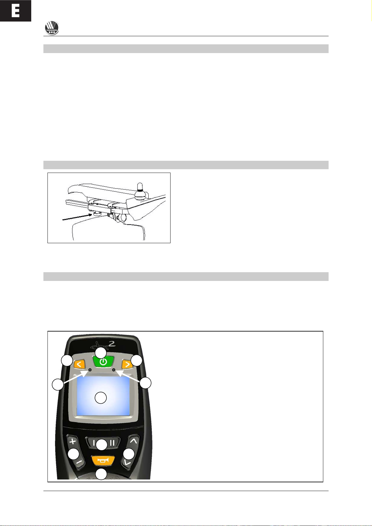
ADJUSTING THE STEERING UNIT
The steering unit's horizontal position can be changed
by loosening screw (1). The unit can then be adjusted
as desired, or removed. Screw (1) must then be
retightened properly. If screw (1) is p u lled to the side,
the steering unit can be tu r n e d to the side.
L Make sure that the steering unit's connection cable stays clear of the pincer mechanism.
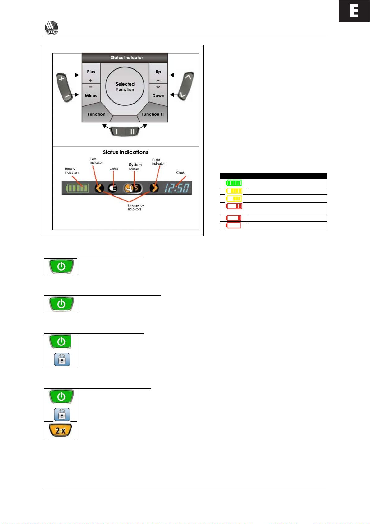
DX2 STEERING UNIT
The steering and control unit built into your electric wheelchair enables you to control all the vehicle's
driving, steering and braking processes and to control other adjusting motors (options: lifting column
and seat/back adjuster and leg supports). The wheelchair's electrical unit and electronics are
constantly being monitored internally. Any fault in the electronics is indicated on the operating display
(6) a nd the status display (1) a n d , if n e ce s sa ry , the wheelchair may be switched off for reasons of
safety (see the chapter on fault analysis).
1 = Display (colour)
2 = "ON / OFF" button
3 = "LEFT INDICATOR" + "LIGHT" button
4 = "RIGHT INDICATOR" + "WARNING INDICATOR" button
5 = "HORN" button
6 = Fault code/operating display
7 = Brightness sensor
8 = "DRIVE PROFILE" button
9 = "SELECT FIELD" button
10 = "SELECT MENU" button
1 2 3
4 5 6 7 8
9
10 1
Page 7
E
TRACER
01/2010
5
The function buttons (8), (9) and (10)
enable functions to be selected that
are displayed in the assigned fields on
the screen.
The status display is constantly visible
in the upper part of the display and
always shows the batteries' charge
level and the current time.
The light, indicator and warning light
displays only appear when the
relevant function is selected. The
system status display appears when
there is a fault or an event, and
displays the relevant event or fault
code (1-12).
Display
Meaning
Battery fully charged
Battery fully charged
Battery half charged
Battery will soon be low, charge
it
Battery is low, charge it soon
Battery is dead, charge now
Start the steering / control unit
Press the ON/OFF button (2) and the operating display (6) will briefly flash on and the
screen will show the drive level (1-5) last used.
Switch off the steering / control unit
Press the ON/OFF button (2) and the system will switch off.
Lock the steering / control unit
If you keep the ON/OFF button (2) pressed for longer than 4 seconds, the steering unit
will be locked.
The lock symbol will briefly appear in the display.
Unlock the steering / control unit
When the ON/OFF button (2) is pressed...
... the lock symbol will appear in the display.
When you press the horn button (5) twice while the lock symbol is showing, the control
unit will be unlocked. The drive level (1-5) last used will appear in the display (1-5).
4 secs.
Page 8
E
TRACER
01/2010
6
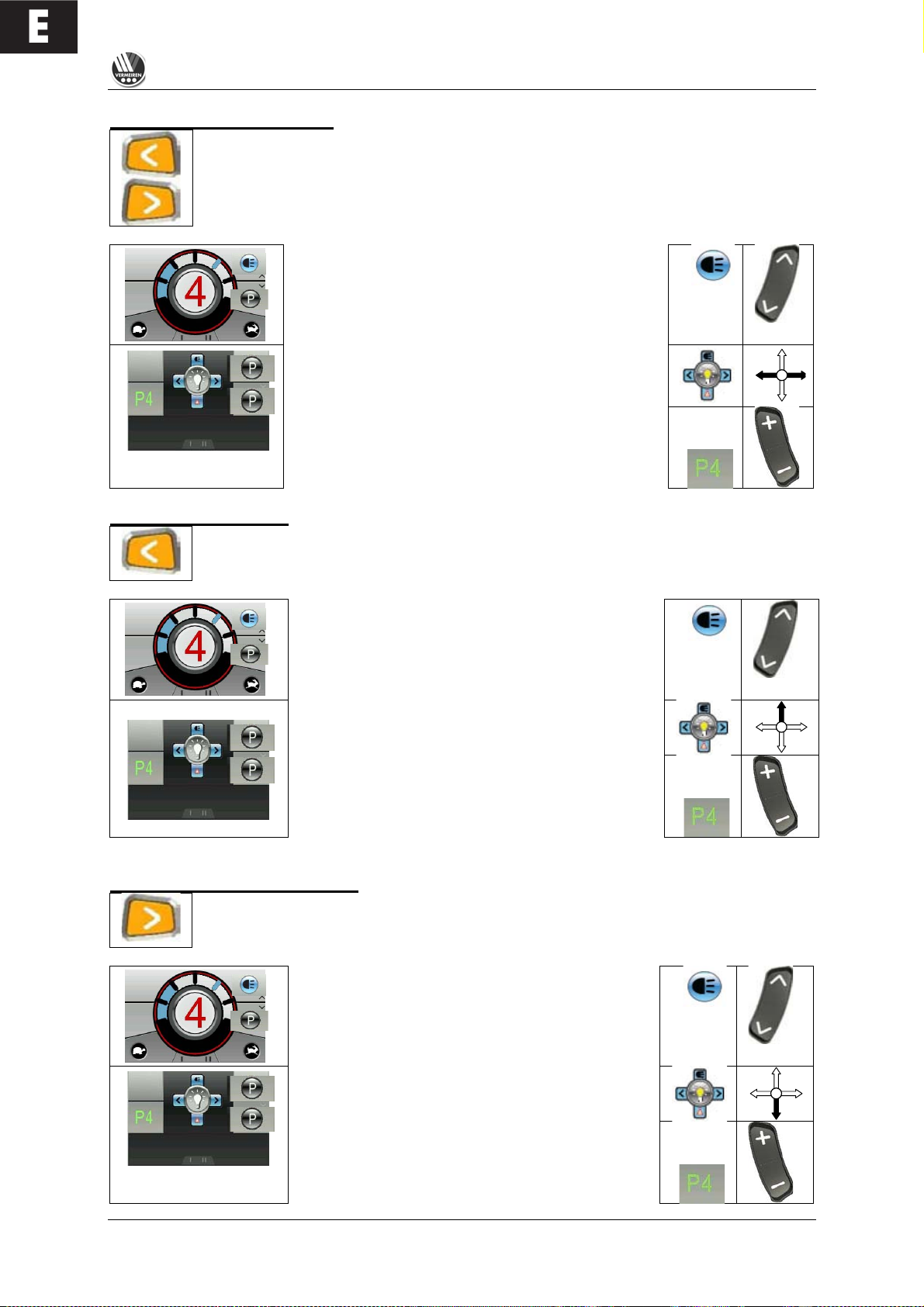
Switch the indicators on/off
To switch the drive direction display on and off, press buttons (3) or (4) for whichever
indicator you wish, left or right. When you activate a drive direction, it will flash in the
status display.
or
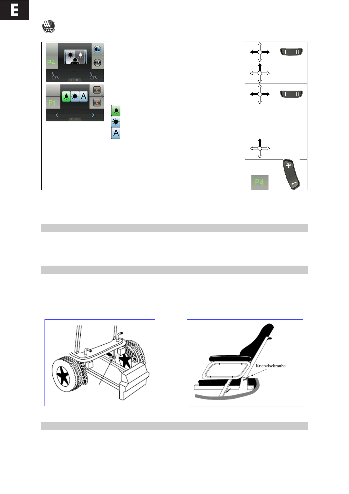
Select the light function using the field selection
button (9) and the display will show the light selection
menu.
To switch the flash function (left or right) on or off,
move the joystick in the appropriate direction left or
right.
To switch back to the driving program, select the
drive profile button (8) in drive mode.
Switch the light on/off
To switch the light on and off, keep the button for the left-hand indicator (3) pressed for
longer than 3 seconds. When the light function is switched on its symbol will light up in
the status display.
or
Select the light function using the field selection
button (9) and the display will show the light
selection menu.
Push the joystick upwards to switch the light on or
off.
To switch back to the driving program, select the
drive profile button (8) in drive mode.
Switch the warning light on/off
To switch the warning light on and off, keep the button for the right-hand indicator (4)
pressed for longer than 3 seconds. When the warning light function is switched on its
symbol will light up in the status display.
or
Select the light function using the field selection
button (9) and the display will show the light
selection menu.
Push the joystick downwards to switch the
warning light on or off.
To switch back to the driving program, select the
drive profile button (8) in drive mode.
Page 9
E
TRACER
01/2010
7
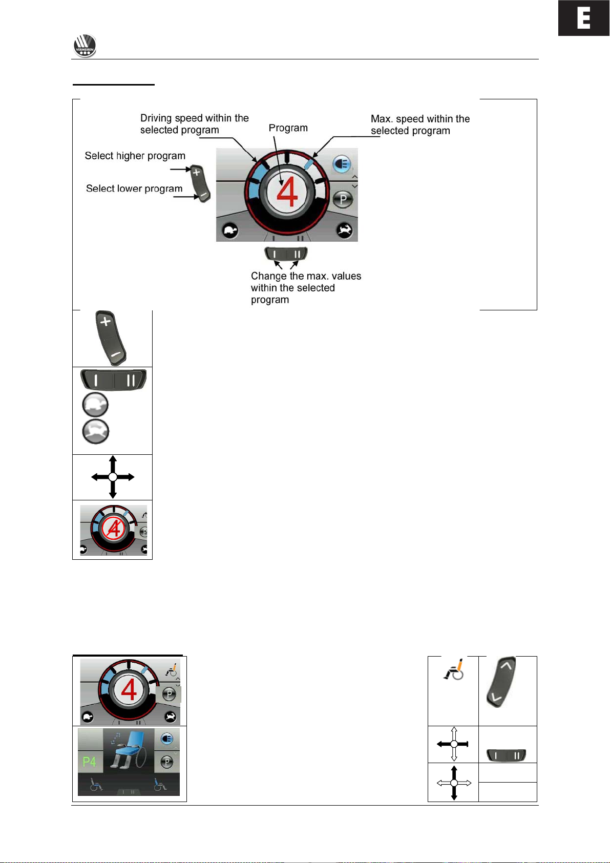
Drive functions
In drive mode use the drive profile button (8) to select a higher or lower driving
program (drive profile 1-5). These drive programs are programmed in the factory
to rise from slow to fast. T h e d rive p ro g ra m you select a ppears in red text in the
middle of the display.
slower faster
The top speed in any drive program can be changed using the menu selection
button (10) in the drive program selected.
To drive the wheelchair in the direction you wish, m ove the joystick to the position
you want.
If the loading socket is p lugged in, the wheelchair w ill b e lo c k ed for drive functions.
If the joystick is moved, the d is p la y will also briefly show a red wa rning bar.
L Make sure that the steering lever is in the neutral (central) position when pressing the on/off
button, otherwise the electronics will be blocked. This block can be lifted by switching the
control unit off and then on again.
L Always adapt your speed to the prevailing environmental conditions.
Electric adjustments
Select the program function using the field
selection button (9) and the display will show the
menu for the adjust functions.
Select left/right with the joystick or the menu
selection button (10) until the adjust function you
want appears in the centre of the display.
Return
function
To adjust the selected function, move the joystick
in the direction you w a nt up or down.
Start
function
Page 10
E
TRACER
01/2010
8
To switch back to the driving program, select the
drive profile button (8) in drive mode.
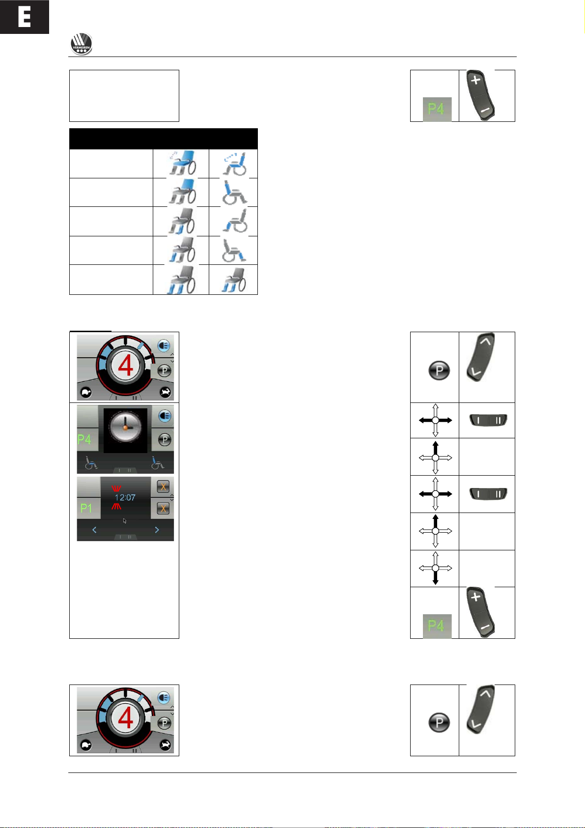
Adjust function
In
Display
Display
Menu
Seat inclination
Angle of backrest
Leg support
left
Leg support
right
Leg supports
simultaneous
The only functions displayed in the menu selection and
the centre of the display are those which exist on your
wheelchair and have been enabled.
L Make sure that no objects and/or persons are
inside the swinging range of the adjust functions,
since this could cause damage and/or injury.
L For your safety the adjust functions can only be
activated when all four wheels of the wheelchair
are standing still. The driver programs are
disabled while the adjust functions are active.
Set time
Select the program function using the field
selection button (9) and the display will show the
menu for the special functions.
Select left/right with the joystick or the menu
selection button (10) until the time function you
want appears in the centre of the display.
If you want to set the time, confirm by moving the
joystick upwards.
The time digit waiting to be set flashes. To change
other digits, you can select left/right with the
joystick or use the menu selection button (10).
To adjust the digits, select upwards with the
joystick.
To save the new time, confirm by moving the
joystick downwards.
To switch back to the driving program, select the
drive profile button (8) in drive mode.
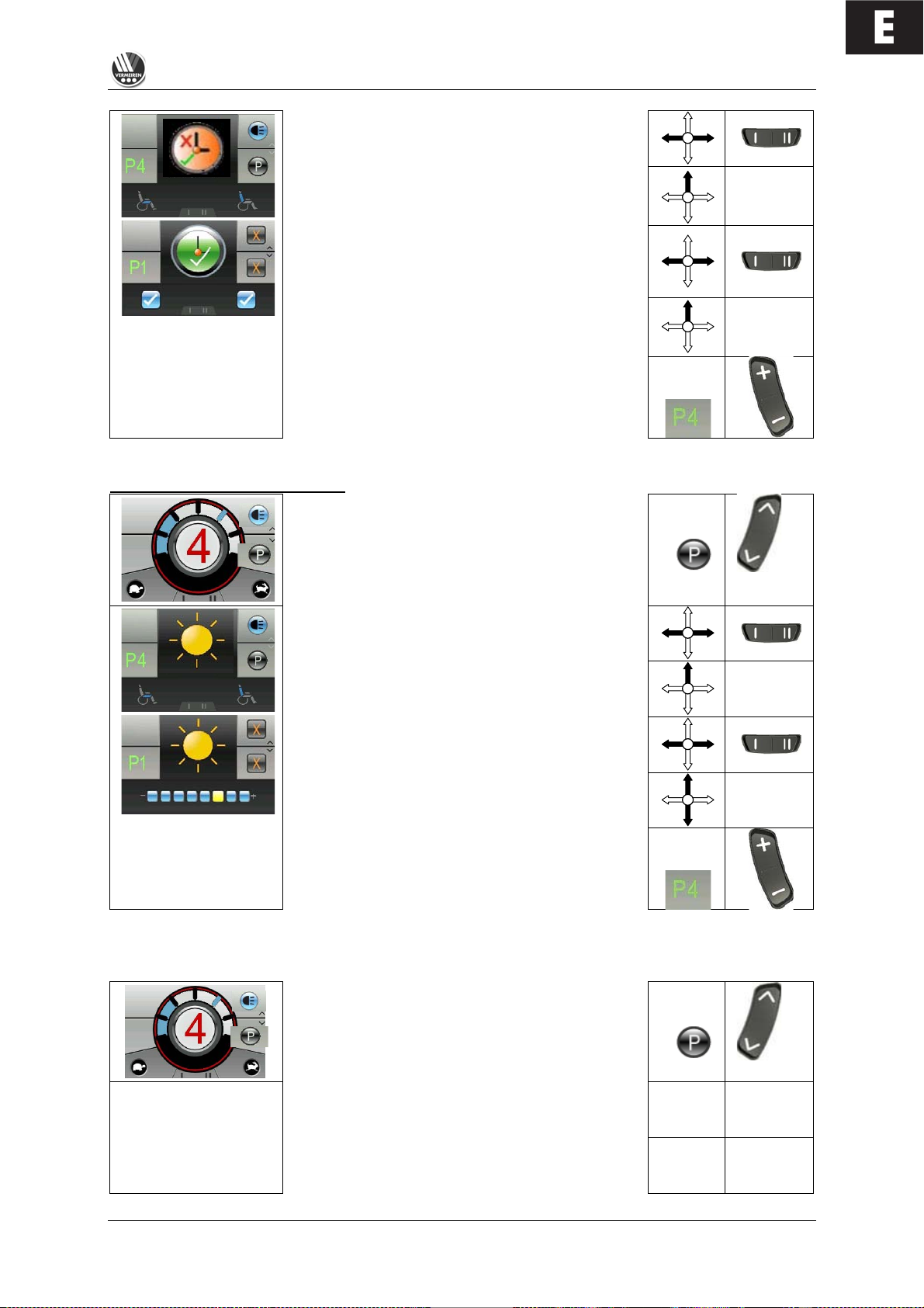
By default, the factory sets the time to be visible in the status display. To change this option, proceed
as follows:
Select the program function using the field
selection button (9) and the display will show the
menu for the special functions.
Page 11
E
TRACER
01/2010
9
Select left/right with the joystick or the menu
selection button (10) until the time function you
want appears in the centre of the display.
If you want to change the display option for the
time, confirm by moving the joystick upwards.
The option currently selected will appear in the
menu and the centre of the display. To change
this, select left/right with the joystick or the
left/right menu selection button (10).
To save the option you want, confirm by moving
the joystick upwards.
To switch back to the driving program, select the
drive profile button (8) in drive mode.
Adjust the screen brightness
Select the program function using the field
selection button (9) and the display will show the
menu for the special functions.
Select left/right with the joystick or the menu
selection button (10) until the brightness function
you want appears in the centre of the display.
If you want to change the brightness of the
display, confirm by moving the joystick upwards.
Adjust the brightness of the display by moving the
joystick left/right or selecting the left/right menu
selection button (10).
To save the brightness you have selected, confirm
by moving the joystick upwards or downwards.
To switch back to the driving program, select the
drive profile button (8) in drive mode.
By default, the factory sets the brightness of the display to be automatically adjusted to match the light
conditions. To change this function, proceed as follows:
Select the program function using the field
selection button (9) and the display will show the
menu for the special functions.
Select left/right with the joystick or the menu
selection button (10) until the brightness function
you want appears in the centre of the display.
If you want to change the brightness function,
confirm by moving the joystick upwards.
Page 12
E
TRACER
01/2010
10
Select left/right with the joystick or the menu
selection button (10) until the brightness function
you want appears in the centre of the display.
If you want to chan g e the brightness function,
confirm by moving the joystick upwards.
Adjust the display's brightness function by moving
the joystick left/right or selecting the left/right
menu selection button (10).
= inwards
= outwards
= automatically (via light sensor (7))
To save the brightness function you have
selected, confirm by moving the joystick upwards.
To switch back to the driving program, select the
drive profile button (8) in drive mode.
If you have special r e q uirements, you can as k your
specialist dealer to enter an individual driving program.
SEAT AND BACK
In the standard version your TRACE R has a fixed sea t and a fixed backrest which can b e adjusted
mechanically. As an optional extra the seat can be inclined electrically and the back can also be
adjusted electrically.
MECHANICAL ADJUSTMENT OF THE BACK
For easier stowing of the electric wheelchair in a vehicle, the back can be folded down forwards or
backwards. Open the lid of the battery box (see the chapter "Removal and replacement of the
batteries"). Above the battery box on the right-hand side are bolts which can be pulled out quickly by
loosening the clasps. You ha v e no w s eparated the connection between the back and the frame. The
backrest can be tilted to the front or to the rear, and removed, after loosening the screw handles on
the lower side of the bac k u n it. (The back can be fixed ag a in b y reversing this process).
ELECTRIC SEAT INCLINE (option)
If you chose th e electric seat tilting option, your wheelchair will have been fitted with the system before
delivery. To operate this, it is only necessary to switch the steering unit on. The driving program then
switches itself on. If you want to adjust the angle of your seat, you just need to use the function button
for adjusting the seat. T h e c o n tr o l in d ic a to r on the DX control unit s h o ws that you have selecte d th is
Lever screw
Fig. B
Fig. A
knob
Page 13
E
TRACER
01/2010
11
function (on the G90 co n tro l unit, the selected symbol flashes). You can then ad ju st the slope of the
seat by pushing the joystick fo rwards or pulling it backward s .
L Make sure that no objects and/or persons are inside the swinging range of the wheelchair,
either in front or at the rear, since this could cause damage and/or injury.
L For your safety this adjust function can only be activated when all four wheels of the
wheelchair are standing still. When this function is selected, the driving program is disabled.
ELECTRIC BACK ADJUSTMENT (option)
The back can be adjusted in a similar way to the seat angle. You only have to select button the
relevant button on the steering unit an d y ou c an the n tilt the ba c k a s y ou w ish .
L Make sure that no objects and/or persons are inside the swinging range of the wheelchair,
either in front or at the rear, since this could cause damage and/or injury.
L For your safety this function can only be used when all four wheels of the wheelchair are
standing still. When this function is selected, the driving program is disabled.
L Make sure that you do not set the backrest too far over backwards, since this can displace the
centre of gravity too far to the back and cause tipping over.
L For your own safety you should not drive the wheelchair in an inclined or tilted position, since it
would severely limit your visibility.
LEG SUPPORTS
The basic model of your electric wheelchair is equipped with leg supports which allow your legs to rest
comfortably. You can adjust the length of the foot supports continuously, turn them aside, or even
remove them completely. T h es e adjustments s hould be carried out by a third person w ith the required
technical knowledge. Consult your specialist dealer if these adjustmen ts become necessar y. If you
want to carry out these adjustments yourself, you should read the following sections carefully.
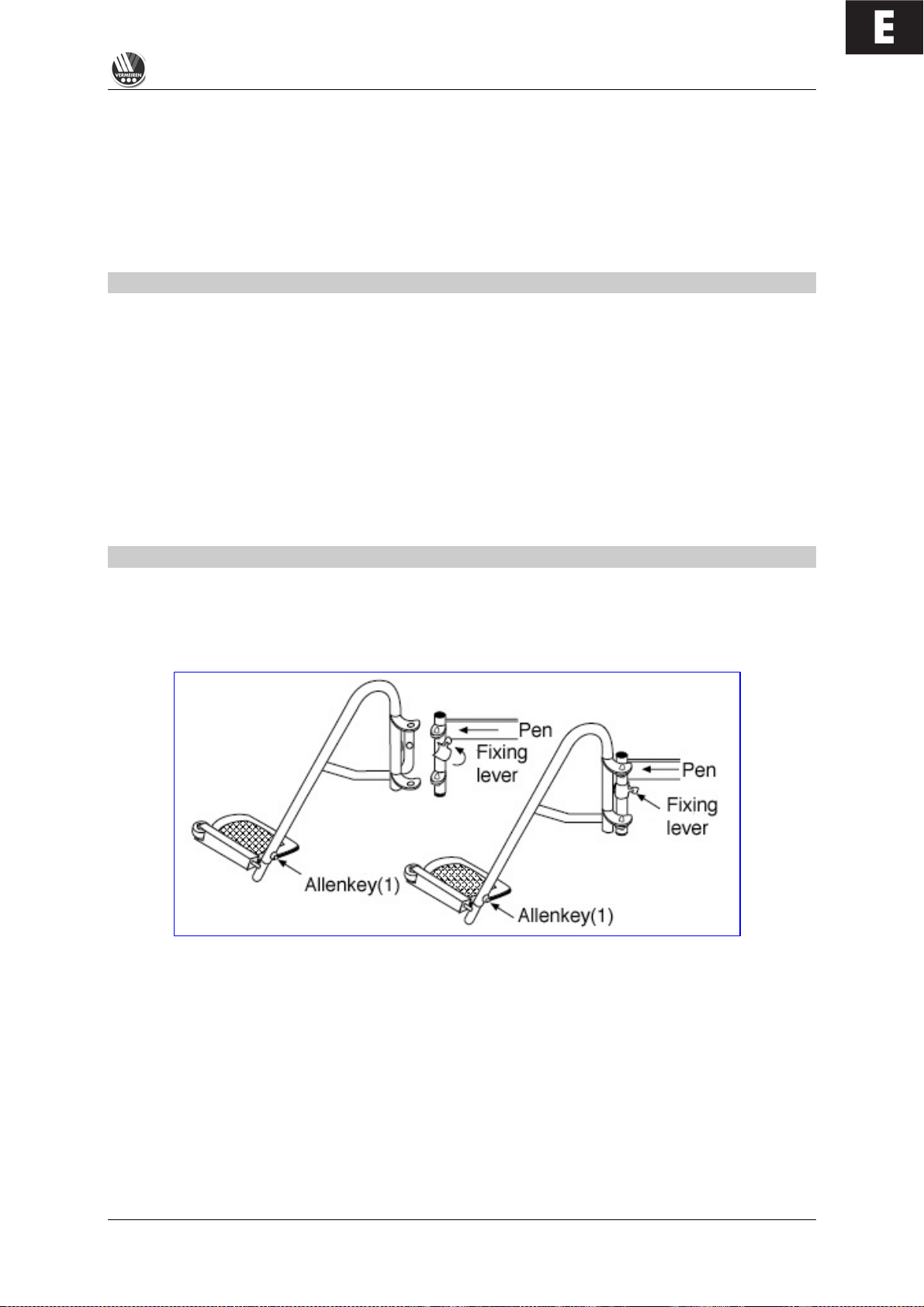
When you want to fix the footrests, hang one leg support sideways on the outside and then turn it
inwards until it stops. The fixing lever (F igure B) must point backwards. If the leg s u pports do not
engage immediately, push them lightly inwards. Do the same on the other sid e. To remove the
footrests, reverse this pro cess.
L When handling the leg supports, make sure that you hold on to the upper curve to prevent
your fingers from getting caught and hurt.
Turn the footplates out of the way for climbing in and out com fortably. T he footplates are designed for
resting your feet securely on them; in addition, your fe e t are pre ve n ted from moving sideways
unnecessarily. Use the Allen keys provided to adjust the length of the leg supports. There is a
countersunk Allen screw (Figure A) on the rear side of the leg support for fixing the footplate. By
loosening this screw th e footplate can be adjusted to the length of your leg. It mus t b e tightened
properly afterwards.
Fig. A
Fig. B
Page 14
E
TRACER
01/2010
12
1
2
Frame
L Make sure that the footplate is at least 6 cm above the ground to avoid scraping the ground
when moving. This could damage the wheelchair and endanger its operational safety. The
user might also get hurt.
L Do not stand on the footplates; they are only designed for letting your feet rest on
them.
L When the leg supports are adjusted, no persons or parts should be within their reach,
otherwise there is danger of injury and/or damage.
If there are patterns of illness and/or disabilities which mean ther e is no guarantee that your legs
would rest constantly on the leg supports, you may select from other available leg supports. Kindly ask
your specialist dealer if you have queries in this regard.
ARMRESTS
The height of the armrests can be adjusted by
loosening screw (1) and pulling the armrest
upwards.
To adjust the width between the armrests, you only
have to loosen screw (2) and place the armrest in
the desired position. The s c r e w must be tightened
properly afterwards.
L Make sure that all fixing screws are properly
tightened b e fo re using the whe e lc h air,
otherwise injury and/or damage can be
caused.
L Never pick the wheelchair up for transportation by grasping the armrests, but take hold of solid
frame parts only.
The armrest containing the steering electronics can only be detached if the electronics have been
removed previously.
L The armrests may only be removed when there is no chance of the wheelchair user
falling out sideways.
If chan g e s , damage, or wear of the suspension are noticeable, kindly consult your specialist dealer
who can remedy these defects.
L To avoid endangering your safety, do not use the w heelchair if you see that the mountings have
changed, been damaged, or have worn out.
L If you make any changes to the armrests and/or the armrest retainers, you do so en tirely at
your own risk. Then your insurance claims lapse immediately.
BATTERY CHARGER
To charge the batteries, only use the battery charger supplied - IMPULSE S (8 A).
Primary voltage
230 Vac – 50/60 Hz – single phase
Secondary nominal voltage
24 V
Secondary maximum voltage
35 V
Secondary power
max. 8 A
Battery type
Lead-sulphuric acid: gel
Battery capacity
60 Ah – 85 Ah (80% capacity charged within 8 hours)
Safeguards
Protected against reverse polarisation, electrical
surges and extreme temperature
Nominal output
270 W
Efficiency
min. 80% (when fully loaded)
Page 15

E
TRACER
01/2010
13
Ambient temperature
0° C to +40° C
Unit dimensions
H 70 x W 150 x D 200 mm
Protection range
IP 21, Protection Class II
Total weight
Approx. 1.3 kg
Mains cable length
1.9 m
Charge cable length
2.4 m
Ambient storage temperature
-15° C to +50° C
Relative storage humidity
max. 95% (non-condensing)
Conformity
EMC Directive 89/336/EEC
Low Voltage Directive 73/23/EEC
We reserve the right to introduce technical changes.
CHARGING THE BATTERIES
As the IMPULSE S (8 A) charger aligns the charge curve with the AGM batteries' charge level, you
can recharge your wheelchair after each use. This avoids any aggressive battery charging and the
"memory effect".
Recharge the wheelchair, at the latest, when the charge indicator on the steering unit goes into the red
zone. If, despite this, you continue driving, eventually only the last red diode lights up and flashes
continually, indicating that the batteries are nearly flat. If you disregard this warning signal, too, an
error message will shortly appear indicating that the batteries can no longer provide power for driving.
The batteries should therefore be charged before these error messages appear, using the supplied
battery charger IMPULSE S (8 A). Avoid the batteries becoming drained, in any case.
• SETTING UP THE CHARGER
When setting up the charger, ensure that it is well-ventilated on all sides. A minimum of 10 cm space
should be left free around the unit for this purpose. If the charger is insufficiently ventilated so that the
unit heats up, the charging rate will fall which will extend the charging time. If the charger overheats (>
+50° C), it will stop charging.
The charger should only be used from a wall socket with a voltage of 230V – 50/60Hz and in wellventilated, dry areas.
• FIRST USE
First put the plug into the wall socket. After an LED combination has lit up, the charger switches to
STANDBY. Both LEDs (green and yellow) are active.
Next, connect the charger cable with the three-pin plug to the loader socket on the electric
wheelchair's steering unit. Once connected to the batteries, the charger automatically begins charging.
Now only the yellow LED is active.
When charging is complete, the yellow LED goes out and the green LED comes on. Now remove the
charger cable from the steering unit. The charger switches back to STAND-BY mode (yellow and
green LEDs active).
If the charger cable is not removed, a tiny current will keep the batteries topped up (trickle charging).
L When charging is complete, always remove the plug from the steering unit first and only then
the mains plug from the wall socket.
• INDICATORS
Yellow LED
Green LED
Charger switched off (not plugged into the mains)
!
!
"
!
Charger has just been switched on and displays the
charging characteristic that has been set
!
"
Stand-by
#
#
Charging
#
!
Full
!
#
Fault
"
"
! = Off # = On " = Flashing
Page 16
E
TRACER
01/2010
14
If you decide not to use your electric wheelchair for an appreciable period, you must nevertheless
recharge it regularly to keep it in a running condition ready for immediate use.
L If the batteries are not used for an appreciable period, they discharge slowly by themselves
(drainage). Then it becomes impossible to recharge them with the battery charger supplied.
So charge the batteries at least once a month even if they are not being used.
L Only use the battery charger supplied to charge the batteries.
L The manufacturer accepts no liability for damage caused by improper charging.
L Never interrupt the charging cycle. The charger shows when the charging cycle is finished.
(green LED remains active).
For further information, please refer to the user instructions provided with the charger.
BATTERIES
The standard for your electric wheelchair is two closed, 12V/70Ah AGM batteries. The batteries used
with your electric wheelchair are drive batteries which only attain full capacity after a few charging and
use cycles.
If the batteries lose their power after long usage, or if they are damaged, get them both replaced by a
specialist dealer only.
L We accept no liability for damage caused through using other types of battery.
L Do not use the batteries at temperatures below +5°C or above +50°C (the ideal is: +20°C).
L If the batteries are opened, all manufacturer liability and all claims will become void.
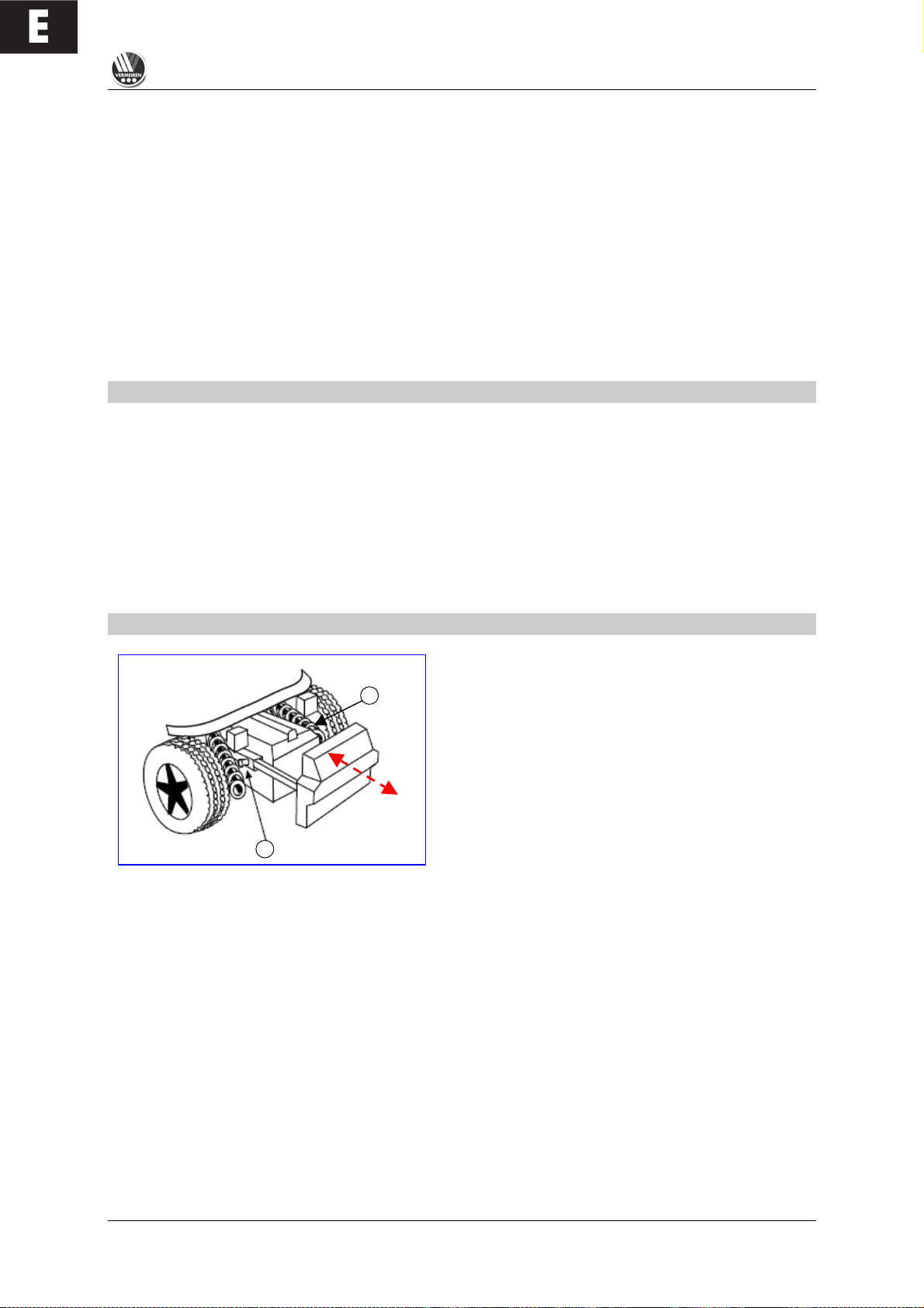
REMOVAL AND REPLACEMENT OF THE BATTERIES
Kindly obey the following instructions when removing the batteries for servicing or for transportation:
Pull up the knobs (1) and pull the battery drawer
backwards. Now you can grasp the first battery by its
handle and pull it backwards on the rail. Then you can
lift the first battery out of the wheelchair by means of
the handgrip on the battery box. To remove the
second battery box, push your hand beneath the
battery box. There is a hollow which allows you to
take hold of the battery box from below and pull it
backwards with a slight upwards motion.
Now this battery box can also be lifted out of the wheelchair by grasping the handle. When replacing
the battery boxes, you reverse the process and only need to push the battery boxes backwards.
L To avoid bruising, make sure that your hands are not caught between the handle and the
frame tube when battery boxes are pulled out.
L Make sure that the batteries are safely put down outside the wheelchair.
L When replacing the batteries, make sure that they are positioned correctly and that the plugs
on the battery boxes are on the left side.
L Both connectors of the battery boxes, one at the front and the other at the rear, must be
plugged in first, otherwise there is no connection to the electronics.
L Make sure that the plugs are connected properly after replacing the battery boxes. If the rear
cover does not fit over the knobs (1), it means that the plugs have not connected properly.
When transporting the wheelchair, it is not necessary to remove the batteries from their boxes. When
removal of the batteries becomes necessary (e.g. replacing the batteries), note the following:
• Remove the battery box lid by loosening the screws on the handle.
• Lift the lid off.
1
1
Page 17
E
TRACER
01/2010
15
• Put the handle back on the battery to allow it to be carried.
• On one side the battery box is connected to the battery by an Allen screw. Unscrew this and
remove it.
• The battery can be lifted out of the battery box by the handle after the pole clamps have been
removed.
• Reverse these processes when replacing the batteries.
L These tasks should be undertaken by the specialist dealer.
L Make sure that no tools or other conducting objects make contact with both poles of the
batteries, or the resulting electric currents can cause injuries.
L No work involving the batteries and the electronics should be undertaken in damp conditions.
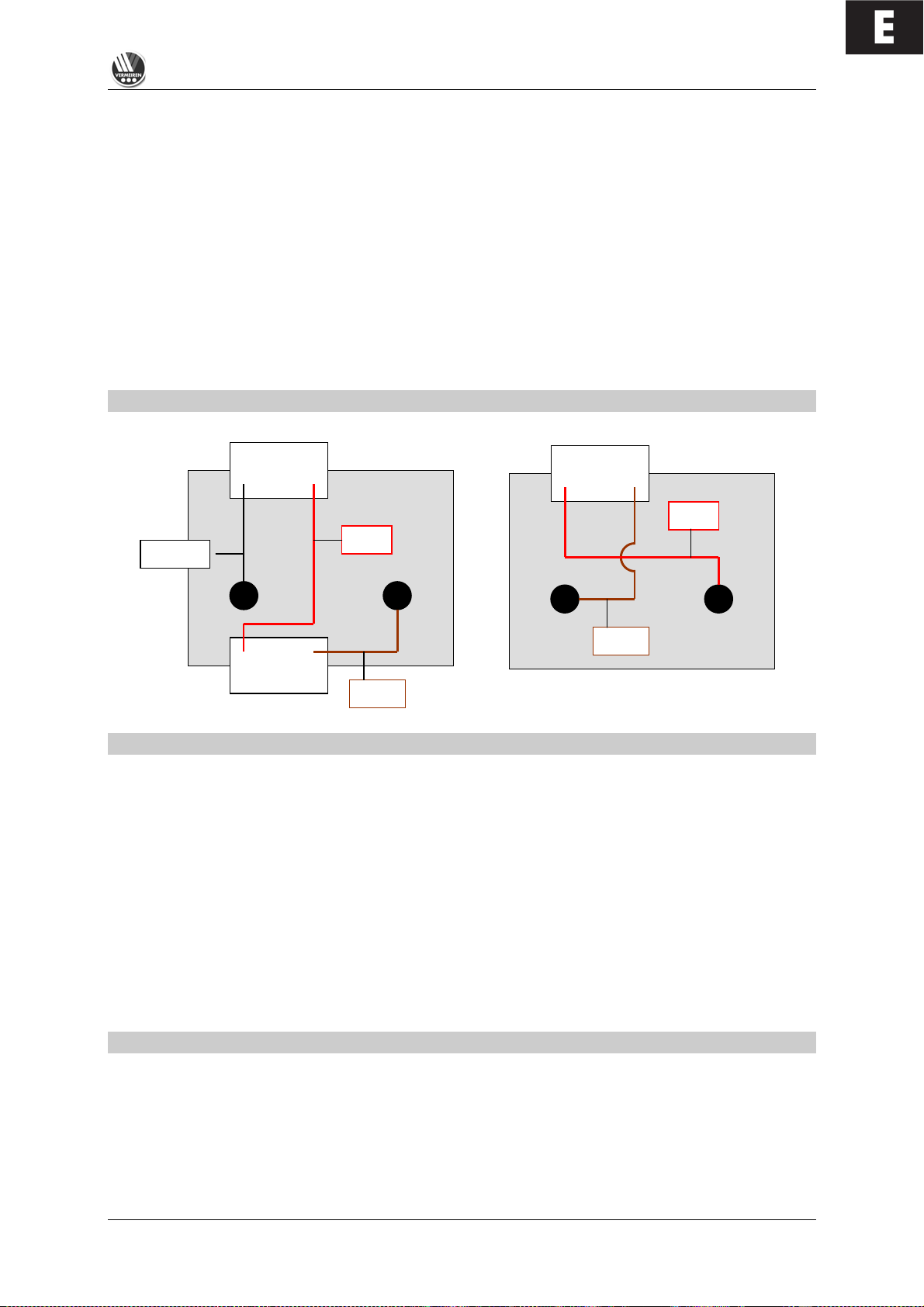
L When connecting the batteries, you should consult the circuit diagram on the battery box lid.
L The manufacturer is not liable for damage/injury caused by improper handling.
BATTERY CONNECTIONS
BATTERY STORAGE
If you do not use your wheelchair for a long while, you can leave it connected to the battery charger.
Charging is automatically controlled by the battery charger. If you remove and store the batteries,
kindly note the following:
• Remove the cable clamps from the poles of the battery.
• The positive pole must be covered by at least one pole cap.
• Only grasp the batteries by two opposite sides of the unit.
• Ensure no objects get in between the poles (a short-circuit could occur!).
• Batteries should only be stored in dry, well-ventilated spaces at a temperature between +5°C and
+45°C.
• Leave batteries in their battery boxes so they are protected from damp, etc.
• Protect the plugs and sockets of the battery boxes against corrosion.
• Protect the batteries against drainage (see "Charging the batteries" section).
L If batteries are not used, they can completely drain.
Your dealer will be happy to advise you on storage and with inspecting your batteries.
THERMAL FUSES
To protect the motor against overload, on the right side of the seat frame there is a thermal fuse that
will automatically cut off the motor to prevent overheating and thus rapid wear and tear or
breakdowns. This can occur if you go up or down slopes that exceed the maximum gradient indicated.
Nominal loads exceeding the maximum could also trigger the safety mechanism. If you try to drive
with the brakes on, it could also result in overload. The values to comply with are indicated in the
“Technical Details” section. To be able to use the wheelchair again, remove the overload and wait till
the motor has cooled off, and then gently press in the thermal fuse again. The system is now ready for
use again.
Battery I
- +
24 V
- +
!
!
Black
Red
Brow
- +
Battery II
+ -
Brow
Red
OUTPUT
Page 18

E
TRACER
01/2010
16
PARKING BRAKES
In addition to electromagnetic braking, your electric wheelchair can also be equipped with fixed
braking for each driving wheel. These must then be set for the wheels. When pneumatic tyres are
used, the parking brake can only function when the tyres are inflated hard enough (see the section
"Technical details").
L Note that the tyre pressure should always correspond to the values given in the section "Technical
details", otherwise the action of the parking brakes would be reduced or even be zero.
L Note that the parking brakes are not supposed to be used for braking while driving. The real
function of the parking brakes is to prevent the wheelchair from rolling away after it has
stopped. If it is used for reducing the speed while driving, injury and/or damage could result.
If the brakes lose their function through wear and tear and/or the covers and hoses have been
damaged, we advise you to consult your specialist dealer who has the tools and the knowledge for
repairing / replacing the defective parts.
L When unsuitable tools are used or through improper maintenance
damage and/or loss of function could result.
If you wish to adjust the parking brakes yourself, use a suitable Allen key to loosen the two screws
which hold the brake suspension on the rail. Then push the brake unit to the desired position and
retighten the two Allen screws and check whether the braking action is correct.
L Brake adjustments not complying with the manufacturer's instructions are done at your own
risk (only in the case of built-in parking brakes). No liability is applicable.
L Rather let your dealer adjust the parking brakes; he is trained on our products and will comply
with all relevant prescribed safety measures.
L Note that the parking brakes are not supposed to be used for braking while driving. The real
function of the parking brakes is to prevent the wheelchair from rolling away after it has
stopped. If it is used for reducing the driving speed, injuries could follow.
If you are not satisfied with the braking behaviour of your wheelchair, consult your specialist dealer
immediately; he will then adjust the brakes properly.
L If water, oil, or other kinds of dirt have soiled the wheels of the wheelchair, then the braking
action of the parking brakes would be impaired. Check the condition of the wheels every time
before using the wheelchair.
L If the brakes lose their effectiveness because of wear and tear and/or damage to the
tyres/inner tubes, kindly consult your specialist dealer, since special machines are required for
changing the "PU" tyres. The end-user is not able to change the "PU" tyres.
TYRES
The TRACER electric wheelchair is fitted with 3.00-8 driving wheels (standard pneumatic) and 260x85
steering wheels (standard pneumatic). Consult your specialist dealer about other wheel combinations.
He will advise you as to which combinations are suitable for your individual requirements.
L Make sure that the wheels are always inflated correctly, otherwise the driving behaviour might
be affected. The correct pressures for the tyres are given in the chapter "Technical details". In
addition, you should always check the pressure values appearing on the tyres themselves.
L We do not provide any guarantee for wheels not supplied by the manufacturer.
TYRE CHANGING
If you want to change the tyres or inner tubes, you should note the following:
Before you can remove a tyre, you must let all the air out of the tube, and insert a tyre lever between
the tyre and the rim. Then slowly and carefully push the lever downwards. This will pull the tyre over
the edge of the rim. If you then move the lever along the rim, the tyre will jump out. Now carefully
remove the tyre from the rim and then remove the tube.
L There must be no air in the tube before it can be removed.
Page 19
E
TRACER
01/2010
17
L If handled improperly, the rim might be damaged. We recommend you get your dealer to do
this work.
Note the following before inserting the new inner tube:
Check the rim bed and the inside wall of the tyre for foreign matter and clean these properly if
necessary. Check the condition of the rim bed, especially around the position of the air valve. Please
use only genuine original replacement parts. No liability is accepted for damage caused by nongenuine replacement parts. Kindly contact your specialist dealer.
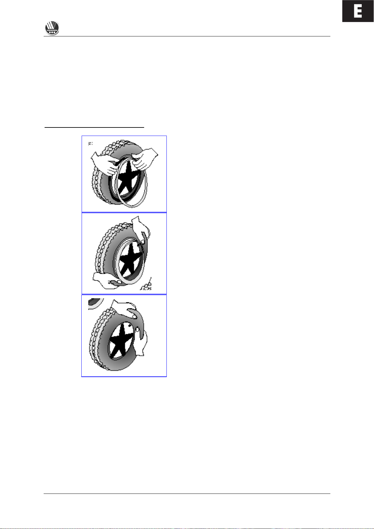
WHEN PLASTIC RIMS ARE USED
Place the rim belt in position over the air valve before
inserting it into the rim. Then the rim belt can be pulled
over easily. Check whether all spoke heads are
covered (in the case of a plastic rim a rim belt is not
required).
Push the tyre over the edge of the rim, starting behind
the air valve. Inflate the tube slightly until it is round,
and place it inside the tyre.
If the inner tube fits snugly inside the tyre without any
folds (if there are folds, let some air out), then you can
push the upper side of the tyre gently onto the rim with
both hands, beginning behind the airvalve.
Check all around on both sides that the tube is not pinched between the rim and the edge of the tyre.
Lightly push the air valve inwards and pull it out again to make sure that the tyre is positioned properly
in the region of the air valve.
To ensure that the wheel is inflated correctly, admit only so much air initially that the tyre can still be
easily pushed inwards by using your thumbs. If the check-lines are equidistant from the edge of the
rim on both sides of the tyre, then the tyre is centered properly. If not - let out the air and position the
tyre afresh.
Now the tyre can be inflated to its full operating pressure (note the maximum) and the valve cap
should be replaced.
Page 20
E
TRACER
01/2010
18
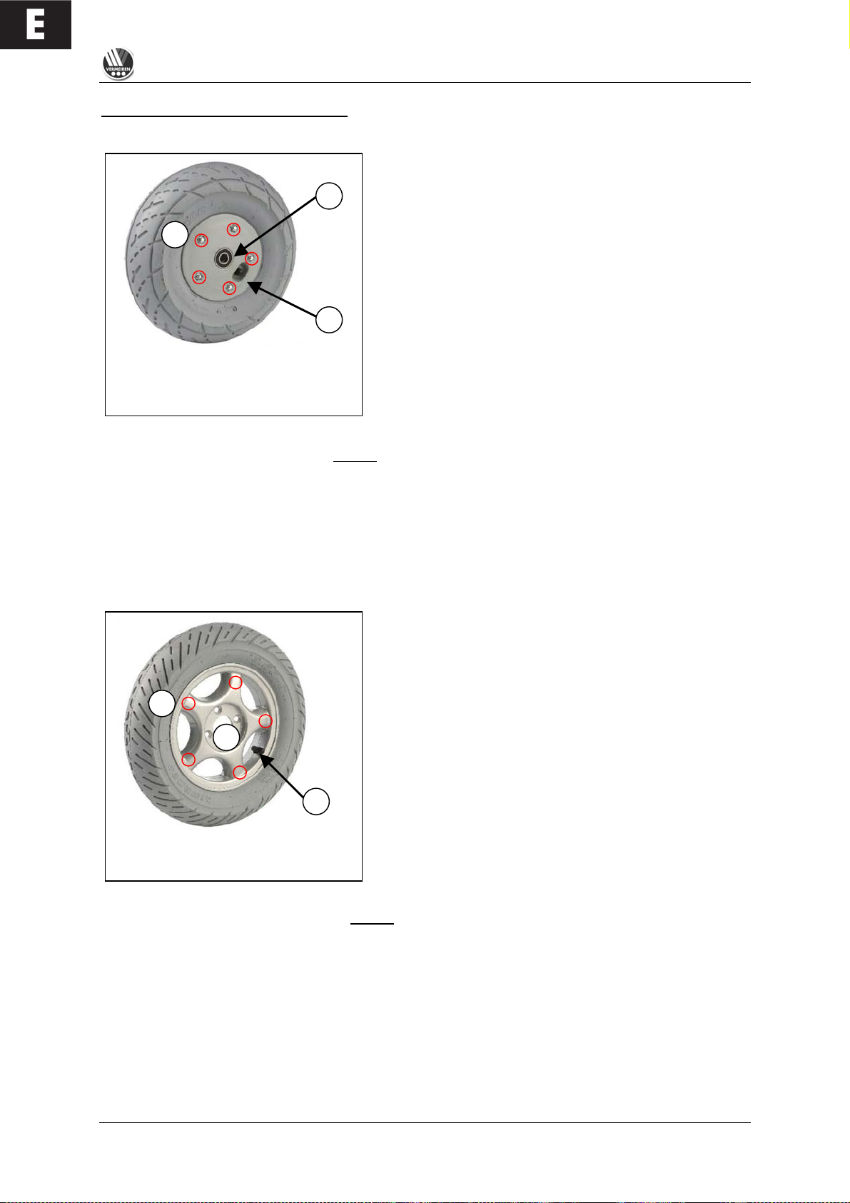
WHEN ALUMINIUM RIMS ARE USED
STEERING WHEELS
A. Loosen the screw on the steering wheel axle and
remove it from the steering whee l fork.
B. Let the air out of the steering wheel by lightly pressing
the pressure pin on the v a lv e .
C. Loosen the 5 screws that hold the split rim together.
Now separate the rim sides.
ASSEMBLY
Insert the partly-filled inner tu b e in to th e ty r e .
C. Connect the two sides of the rim through the tyres and
use the 5 connecting screws to screw the rim
together.
B. Make sure that the valve juts out of the valve opening
in the rim.
A. Put the wheel back into the front wheel fork and inflate
the wheel.
L
Before taking the rim apart always let the air out of the tyres, or the sides of the rim could
come apart explosively and cause injury!
L Make sure that the inner tube does not get caught in the sides of the rim
L Only inflate the wheels to the max. tyre pressure ( see "Technical details")
L Check to see that all the screws on the wheels are firmly tightened before using the
wheelchair.
DRIVE WHEELS
A. Unscrew and remove the axle nut on the drive wheel
and the 4 screws that attach the wheel to the flange.
B. Let the air out of the wheel by lightly pressing the
pressure pin on the valve.
C. Unscrew the 5 screws on the inside of the rim.
Separate the rim sides.
ASSEMBLY
Insert the partly-filled inner tu be into the tyre.
C. Connect the two sides of the rim through the tyres and
screw them back again.
B. Put the valve through the hole for it in the rim.
A. Put the wheel back on the flange and secure the
wheel by hand-tightening the axle nut. Inflate the
wheel to the recommended tyre pressure.
L
Before disassembling the rims, always let the air out of the tyres !
L When assembling, make sure that the inner tube does not get caught between the sides of the
rim.
L Only inflate the wheels to the max. tyre pressure (see "Technical details")
L Check to see that all the screws on t h e wheels are firmly tightened befo r e using the
wheelchair.
L Screw adhesive (e.g. Loctite) should be applied to the screws on the flange. Screw adhesive
will only work if the thread is free of grease and particles.
L Improper assembly voids any warranty claim.
A B C
A B C
Page 21
E
TRACER
01/2010
19
1
1
L When inflating the tyres, always check that the pressure is correct. The correct pressure is
given on the tyre walls (also refer to "Technical details").
L Use only inflating equipment which complies with regulations and indicates the pressure in
bar, or use the supplied air pump. We do not accept any liability for damage caused by using
inflation equipment n o t s u pplied by the manufac tu r e r .
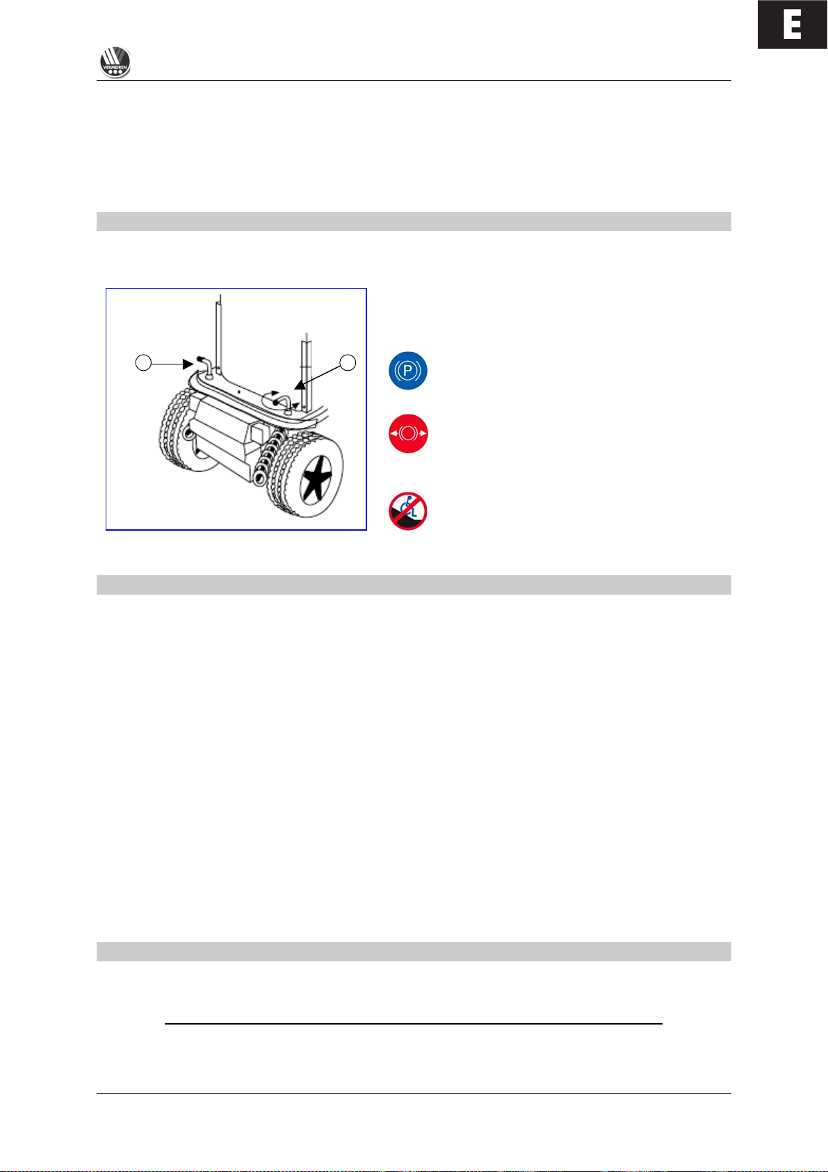
PUSHING THE WHEELCHAIR
The wheelchair can be pushed by an attendant. Turn the locking lever outwards (inwards in the case
of the TRACER 50+); this allows the wheelchair to be pushed freely. Now the wheelchair will no longer
be driven by the motors, nor will it be braked by the motors.
When pushing the wheelchair, make sure that the
controls are switched off and that you only push it on
level terrain.
When the locking lever is in this direction, edriving is enabled; the electromagnetic brake
is activated.
When the locking lever is in this direction,
your wheelchair is in the free-wheeling
position; the electromagnetic brake is
deactivated.
Without the braking effect of the motors which
is abse n t when the wheelchair is being
pushed, the wheelchair can accidentally move
or turn. (Use the parking brakes to secure the
wheelchair !).
TRANSPORTING THE WHEELCHAIR
Before lifting up the wheelchair, all moveable parts must be dismantled (footrests, armrests, and
steering unit).
L When raising the wheelchair, it should only be grasped by fixed parts of the frame.
L To prevent damage, the steering unit and armrests should be removed for transportation.
L When assembling, make sure that all screws are retightened properly.
To prevent the wheelchair from moving about, switch the locking mechanism behind the backrest to
electronic driving (it must be engaged). In addition, engage the parking brakes if present in your
model. If you require further belt securing systems, make sure that they are only attached to solid
parts of the frame.
If you want to be tak e n up or down stairs with the wheelchair, you will need a wheelchair ramp
or wheelchair lift system.
L At least two persons are required to move the wheelchair up or down stairs or over single
steps.
L When being transported, no persons or objects should be below the wheelchair, to prevent
personal injury or damage to the wheelchair.
TRANSPORTING BY CAR
When inside a vehicle the wheelchair must be securely fastened by means of the built-in safety b e lt s
or by specially provided belt systems.
Nobody is permitted to sit in a wheelchair which is transported in a vehicle.
L Make sure that the wheelchair is fastened by fixed parts of the frame only.
L Check that the wheelchair cannot slide in any direction.
Page 22
E
TRACER
01/2010
20
L Engage all parking brakes in addition to the electromagnetic brake of the wheelchair.
L Loose parts taken from the wheelchair must be stowed securely.
For transportation by public vehicles for disabled persons you should request information from the
organisation concerned about compliance with the currently applicable prescriptions and norms for
such transport.
For transportation in other vehicles (airplanes, buses, ships, trams, trains, etc.) you should consult the
operator concerned about whether you and your wheelchair could be safely transported according to
the relevant rules and norms.
L We do not accept any liability for damage and/or injuries resulting from transportation by third
parties. Transportation is at your own risk.
If you have further questions about transportation, kindly consult your specialist dealer.
He/she shall gladly assist you further.
USING RAMPS
If you are considering ramps for overcoming obstacles, kindly note the following:
For your own safety you should drive on ramps at the slowest possible speed. If the wheelchair has
optional adjustment functions, ensure that
1. the back has been set to upright (if there is one)
2. the angled seat has been set to horizontal (if there is one)
3. the leg supports have been set so that no collision can occur while passing the obstacle.
L The manufacturer can accept no liability for any damage or injury that may arise from the
adjustment functions being extended when being used on a ramp.
If another person is pushing you, note that the large weight of the electric wheelchair exerts
appreciable reverse forces.
If your helper does not have the strength to push the wheelchair up the ramp, you must immediately
secure it by engaging the motor adjustment (Notstop).
L Observe the instructions on the maximum load of the ramps used.
L Use a restraining safety belt to secure yourself in your wheelchair.
L We do not accept any liability for injury or damage caused by an improper choice of ramps.
ACCESSORIES
! INDIVIDUAL HEADREST (L55)
The standard backrest can be enhanced by an individually adjustable head support supplied by us.
This comprises a cushioned headrest which can be set in various positions by means of a gearwheel
(see diagram).
The receptacle screwed in the upper third of the back, can be fixed to the centre of the back for
inserting the headrest. The height of the headrest can be adjusted and then tightened at the desired
height. The holes required for fixing the headrest have already been drilled in the back unit.
Page 23
E
TRACER
01/2010
21
1
2
L Make sure that the headrest is inserted at least to the marked position to be fixed securely and
reliably.
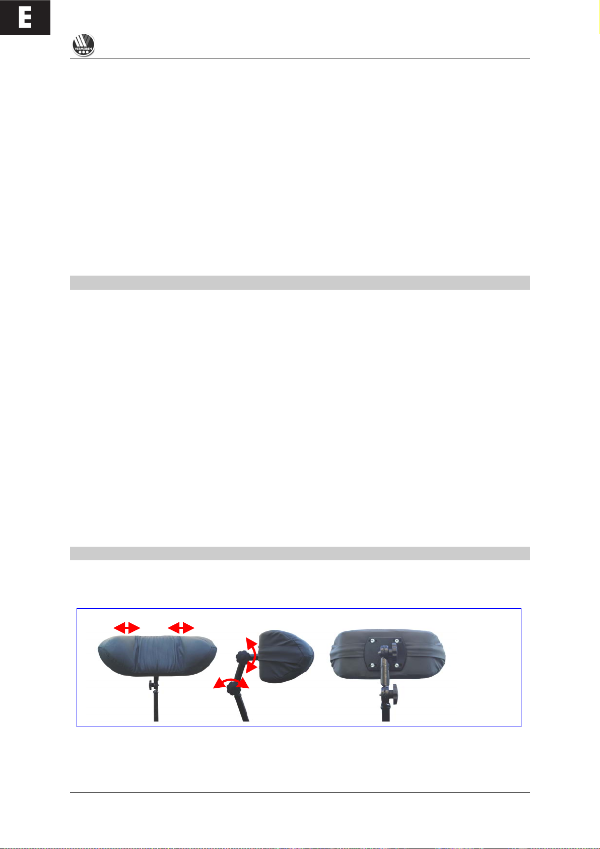
The depth of the headrest can be adjusted by slightly loosening the adjusting screws to allow
movement of the sprocket gears. Then you can adjust the headrest to your needs and secure it by
retightening the adjusting scre w s . If the adjusted position is not satisfactory, you can repeat this
process.
L Ensure that the back of your head is supported when relaxed in an upright sitting position.
L Before using the headrest all fixing screws must be tightened properly, since injuries might
result when it slips downwards unintentionally.
You can secure your head against tipping sideways by lightly pressing the side panels of the headrest
inwards and to the fr o n t.
L Do not exert too much pressure on the side panels otherwise bruising may result.
L Do not clap the side panels together violently, otherwise they might break off, causing possible
injury as well as loss o f fu nction.
Structural alterations to the headrest would void any warranty.
LEG SUPPORTS
If the leg sup ports supplied with the wheelchair do not mee t your requirem e n ts , you could consider leg
supports with adjustable height. Because the footrest attachment is standardised, it can be assembled
in the same way as d e s c r ib ed in the section on foot s upports.
Kindly consult your specialist dealer if you have questions abo u t o ther footrest systems; he shall gladly
advise you about the indication and function of our available foot supports.
PERSONAL SAFETY SYSTEM (B58)
For your safety we offer you a standardised safety belt which is equipped with a snap-on fastener, like
those mounted in cars and v a n s . This can be fix e d by means of bolts inserted in th e bolt holes on b oth
sides of the seat frame next to the backframe attachments. To ensure proper fixing, self-locking
("nylock") nuts should be used.
If the belt has been dismantled, only new genuine nuts provided by the manufacturer should be used
for re-attachment.
L To ensure the validity of the warranty, entrust this work to your specialist dealer.
L Before using the seatbelt, make sure that all screws are properly tighte n e d.
Please consult your specialist dealer if you require other safety belt systems. He/she shall gladly
assist you further.
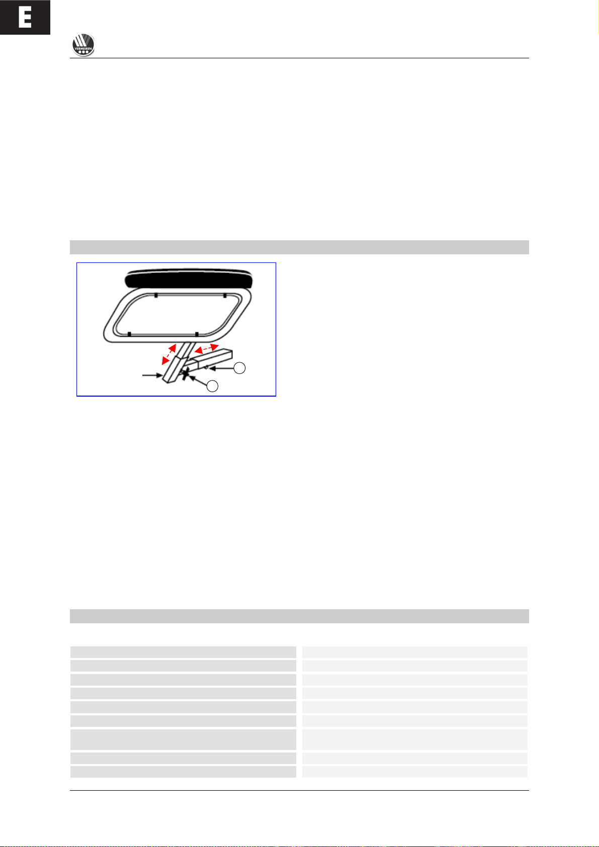
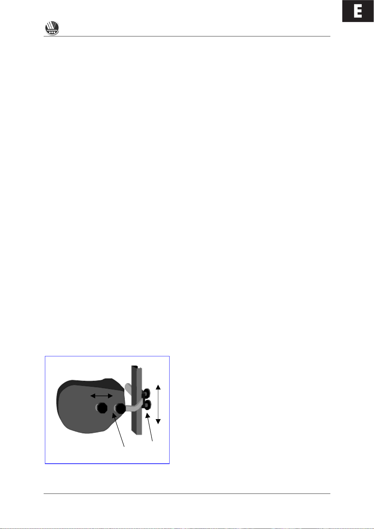
BODY SUPPORTS (L04)
If yo u r uppe r body require s strong e r bracin g than that
provided by the standard backrest, we offer a lateral
support system which can be mounted on the
backrest. The guiding rail is mounted vertically about
6 cm behind the backrest to one side. The screw
threads set in the ba c k , can b e used for this purpose
(older models can be upgraded by using wood
screws). The supporting rods are inserted from the
rear and secured by the two Phillips screws. When
adjusting the height and depth of the supports, slightly
loosen the Philips screws (1) and position the
supports to your liking. Then retighten the Philips
screws (1).
To adjust the depth of the supports, you can loosen screws (2) and set them to the desired depth.
Page 24

E
TRACER
01/2010
22
L Make sure that all screws are properly tightened after the assembly, otherwise the stability of
the supports is endangered, and injury/damage can occur.
L Make sure that the rail system is properly mounted and that nothing obstructs its functional
integrity.
L If the wheelchair is not fully assembled when delivered, only your specialist dealer who has
suitable tools and knowledge of the fittings, may perform the mounting procedure.
L Improper assembly leading to damage voids any warranty claim.
L While the body supports are fitted, you should sit still and in a natural position in your
wheelchair to allow correct fitting.
L Make sure that no objects and/or body parts are located between the supports and the back of
the supports when they are pulled tight, otherwise bruising and/or damage might occur.
If you have further questions about the indications and function of the supports, kindly contact your
specialist dealer. He will be happy to answer your questions.
FOR YOUR SAFETY
Some safety tips are given below for your security:
L To prevent injury and/or damage to your wheelchair, make sure that no objects and/or body
parts are caught in the spokes of the driving wheels.
L Do not step on the footplate when getting in or out of the wheelchair. The footplates must be
folded up beforehand, or the leg supports should be swung outwards out of the way.
L You should investigate the effects of shifting the centre of gravity on the behaviour of the
wheelchair for example on gradients, on laterally sloping ground, or when overcoming
obstacles, only when a helper is present to secure and support you.
L If you want to pick up something (lying in front of, on the side, or to the rear of the wheelchair),
you should not lean too far out to avoid tipping over because of the displacement of the centre
of gravity.
L Always follow the instructions for using your wheelchair. For example, avoid driving without
brakes against an obstacle (step, edge of the curb) or dropping down from steps.
L Stairs may only be negotiated when aided by another person. If devices and furnishings like
ramps or lifts are available, use them.
L Check that the profile depth of the tyres is adequate.
L Obey traffic regulations when driving on public roads.
L When driving your wheelchair, you should not be under the influence of alcohol or medicine as
in the case of driving other vehicles. This also applies to indoor driving.
L When travelling outdoors, adapt your driving to weather and traffic conditions.
L Check that the rear reflectors of your wheelchair are not covered by dirt and/or other objects.
L When driving in the dark, wear bright clothing to be more visible, or clothing with reflectors,
and make sure that the reflectors of the wheelchair are clearly visible.
L Be careful when using sources of fire such as cigarettes, since they can set the seat and back
covers alight.
L Make sure that the maximum load (125 kg for the TRACER / 150 kg for the TRACER 50+) is
not exceeded.
MAKING REGULAR CHECKS
As with any technical product, your wheelchair, too, requires regular checks if it is to be kept fullyfunctional. The steps to be taken to fully enjoy the advantages of your wheelchair even after protracted
use, are described below.
Page 25

E
TRACER
01/2010
23
! BEFORE DRIVING
1. Check the tyres for visible damage and/or soiling. Remove any dirt as it could impair the
motion and road-holding capacity of the tyres. When a tyre is damaged, please go see an
authorized workshop for repair.
2. Use the drive electronics' display to check that the driving, braking and adjustment
features are fully-functional. If these functions are impaired, contact your dealer.
3. Check the pressure of the tyres and inflate them if necessary (see section "Technical
details").
4. Make sure that all screws are tightened properly.
! APPROX. EVERY 8 WEEKS
Depending on the frequency of use check the following:
1. That the armrests are working
2. Movable parts of the footrests
3. The condition of the covers and cushioning materials.
4. The tread depth of the wheels
! APPROX. EVERY 6 MONTHS
Depending on the frequency of use check the following:
1. Cleanliness
2. General condition
3. That the charger is working
4. Operation of the steering wheels
If the rotation resistance is too great, clean the bearings of the steering wheels. If this is
insufficient, please consult your dealer.
L In cases of lost functionality, repairs and inspections, consult your dealer.
CARE
Your electric wheelchair requires regular care to keep it in a pleasant condition. To do this, note the
following:
L Steam or high-pressure cleaning is forbidden !
! COVERS
Clean the covers with hot water. You can remove stubborn dirt by washing with a mild commercial
detergent. Stains can be removed by using a sponge or a soft brush.
L Do not use strong cleaning liquids like solvents, nor use hard brushes.
L We shall decline all liability for damage caused by the use of improper cleaning agents.
L Take care that you do not soak the covers.
! PLASTIC PARTS
Clean all plastic parts of your wheelchair with commercial plastic cleaners. Read the specific product
information and only use soft sponges or cloths.
! SURFACE LAYERS
The high quality of the surface layer guarantees optimal protection against corrosion. If the outside of
the frame has been damaged by scratches or otherwise, you can protect the area by applying varnish
obtainable from your specialist dealer.
! ELECTRONICS CASING
Only wipe the steering unit with a cloth moistened
by a few drops of a commercial domestic cleaner.
Do not use any abrasives or sharp-edged polishing equipment like a metal scrubber or brush, since
these can scratch the surface of the steering unit and destroy its water repelling property.
L Regularly check the plug connectors for corrosion or damage, since it could affect the
efficiency of the electronics.
L Before any maintenance work, disconnect the batteries to prevent any unwanted current flow.
L The manufacturer accepts no liability for damage caused by poor maintenance.
Page 26

E
TRACER
01/2010
24
INSPECTION
In principle we recommend annual inspections, but at least before usage is resumed. The following
checks must at least be performed and documented by authorized persons:
• Check the cabling (especially for: crushing, abrasion, cuts, visible insulation of the inner
conductor, visible metallic veins, kinks, lumpiness, color changes of the outer sleeve, brittle
spots)
• Visual inspection of the frame parts to check for plastic deformation and/or wear and tear
(basic frame, seat frame, back frame, side parts, leg supports, motor suspensions)
• Electric leads to be securely placed to avoid shearing, crushing and other mechanical stresses
and strains.
• Visually check all housings for damage, screws must be securely fixed, seals and gaskets
should not exhibit visible damage.
• Review the charger's residual diversion current (
A
) based on VDE 0702
• Review the charger's insulation resistance (
MO
) based on VDE 0702
• Check the functioning of the armrests and leg supports (locking, load, deformation, wear and
tear caused by loads)
• Check the functioning of the drives (during a test drive " noises, speed, free running, etc.), if
necessary: Measure the performance, first with no load, and then with the nominal load
("SWL") to investigate the wear and tear of the motors by comparing the values of the electric
current with the values at delivery, condition and function of the carbon rod, the condition of
the collector, remove debris from the motor housing and the collector, etc.)
• Check the condition of the batteries, covers, tubes, and tyres.
Checking measurements may only be carried out by skilled persons trained on the wheelchair at least
and at least under the supervision of an electrician who knows the checking instruments and
processes. Only an electrician is able to release the electric wheelchair for use after successful
checking measurements or servicing. The service must be confirmed in the service plan when at least
the above-mentioned aspects have been checked.
L The manufacturer is not liable for damage caused by deficient or improper inspections.
DISINFECTION
Only a hygiene technician or someone appointed by him can disinfect your wheelchair and this should
be done every time before its use is resumed or before it is provided to a different person. All parts of
the wheelchair can be treated with a disinfectant cloth. In principle all surfaces of a system or a
product have to be disinfected before passing it on to another user, or when it is known that the user
carries an infective vector. In these cases the measures of the federal law on epidemics have to be
considered.
Disinfectants may only be applied by authorised persons trained in the functioning and
application of disinfectants.
L Wear suitable protective clothing because the disinfectants can irritate the skin on contact. For
this purpose you should also take note of the product information for the solutions concerned.
L You employ unauthorised persons at your own risk.
L No liability is accepted by the manufacturer of the wheelchair for damage and injury caused by
the improper handling of disinfectants.
Page 27
E
TRACER
01/2010
25
We recommend the following disinfectants for scrubbing (based on the list of the Robert Koch Institute, RKI):
Surface
disinfection
(scrubwashing
Disinfecting excretions
1 part sputum or stool + 2 parts
diluted solution or 1 part urine + 1
part diluted solution
Washingdisinfection
disinfection)
Sputum
Stools
Urine
Diluted solution
Time to take effect
Diluted solution
Time to take effect
Diluted solution
Time to take effect
Diluted solution
Time to take effect
Diluted solution
Time to take effect
Active substance
Name
%
Hrs. % Hrs. % Hrs. % Hrs. % Hrs.
Effective
range
Manufacturer
or
Supplier
Amocid
1
12 5 6 5 4 5 6 5 2 A Lysoform
Gevisol
0,5
12 5 4 5 4 5 6 5 2 A Schülke & Mayr
Helipur
6 4 6 4 6 6 6 2 A
B.Braun Petzold
m-cresol soap
solution DAB 6
1
12 5
4
A
Mucocit-F 2000
1
12 A Merz
Phenol
1
12 3 2 A
Phenol or
phenol derivatives
Velicin forte
5 4 5 6 A
Ecolab
Chloramine-T DAB
9
1,5
12
2,5 2 5 4 A1 B
Clorina
1,5
12
2,5 2 5 4 A1 B
Lysoform
Chlorine, organic or
inorganic substances
with active chlorine
Trichlorol
2
12 3 2 6 4
A1 B
Lysoform
Apesin AP1002
4 4 AB
Tana Chemie
Pure Dismozon2
4 1 AB
Bode Chemie
Perform2
3 4 AB
Schülke & Mayr
Percompounds
Wofesteril2
2 4 AB
Kesla Pharma
Aldasan 2000
4 4 AB
Lysoform
Antiseptica
Surface
Disinfection 7
3
6
AB
Antiseptica
Aldospray Conc.
3 4 AB
Lysoform
Apesin AP30
5 4 A
Tana Chemie
Bacillocid Spezial
6 4 AB
Bode Chemie
Buraton 10F
3 4 AB
Schülke & Mayr
Desomed A 2000
3 6 AB
Desomed
Hospital dis-
infection cleaner
8
6
AB
Dreiturm
Desomed Perfekt
7 4 A
Desomed
Fink-Antisept B
8 6 AB
FINKTEC
Formaldehyde
solution DAB 10
(formalin)
1,5
12 3 4
AB
Incidin perfekt
1
12 3 4
AB
Ecolab
Kohrsolin
2
12 3 4
AB
Bode Chemie
Lyso FD 10
3 4 AB
Schülke & Mayr
Lysoform
4
12 5 6
AB
Lysoform
Lysoformin
3
12 5 6
AB
Lysoform
Lysoformin 2000
4 6 AB
Lysoform
Melsept
2
12 4 6
AB
B.Braun Petzold
Formaldehyde
and/or other
aldehydes or
derivatives
Melsitt
4
12
10 4 AB
B.Braun Petzold
(…)
Page 28
E
TRACER
01/2010
26
Surface
disinfection
(scrubwashing
Disinfecting excretions
1 part sputum or stool + 2 parts
diluted solution or 1 part urine + 1
part diluted solution
Washingdisinfection
disinfection)
Sputum
Stools
Urine
Diluted solution
Time to take effect
Diluted solution
Time to take effect
Diluted solution
Time to take effect
Diluted solution
Time to take effect
Diluted solution
Time to take effect
Active substance
Name
%
Hrs. % Hrs. % Hrs. % Hrs. % Hrs.
Effective
range
Manufacturer
or
Supplier
Minutil 2 12 6 4
AB
Ecolab
Multidor
3 6 AB
Ecolab
Nüscosept
5 4 AB
Dr.Nüsken Chemie
Optisept
7 4 A
Dr.Schumacher
Pursept-FD
7 4 AB*
Merz
Septoclean FDN
3 6 AB
Haka Kunz
Tegodor
3 6 AB
Goldschmidt
Formaldehyde
and/or other
aldehydes or
derivatives
Ultrasol F
3
12 5 4
AB
Fresenius
Franko-DES
2
12 A Franken
Tensodur 103
2
12 A MFH
>Marienfelde<
Lime-wash3
20 6 A3 B
1
Insufficiently effective against myco-bacteria when disinfecting surfaces, especially in the presence of blood.
2
Not suitable for disinfecting blood-contaminated or porous surfaces (e.g. raw wood).
3
Useless for tuberculosis; preparation of lime-wash: 1 part dissolved lime (calcium hydroxide) + 3 parts water.
*Virus effectiveness tested in compliance with the RKI test method [German Federal Health Circular 38 (1995) 242] .
A: suitable for killing vegetative bacterial germs including myco-bacteria as well as fungi, including fungal spores.
B: suitable for deactivating viruses.
The current state of the disinfectants included in the RKI list can be ascertained at the Robert Koch
Institute (Home page: www.rki.de
).
All steps taken for disinfecting rehabilitation equipment and their components or other accessory parts,
are recorded in a disinfection report which contains at least the following information with product
documentation appended:
Table 2 – Example of a disinfection book
Date of the
disinfection
Reason
Specification
Substance and concentration
Signature
Abbreviations used in column 2 (reason):
V = suspected infection IF = infection case W = repetition I = inspection
Kindly consult your specialist dealer if you have further queries about disinfection; he will
gladly assist you.
STORAGE
• Store in a dry place (between + 5 °C and + 45 °C).
• The relative humidity of the air should be between 30% and 70%.
• Air pressure between 700 hPa and 1060 hPa.
• Disconnect the power plug of the battery charger.
• For the batteries, see the chapter on “Battery Storage”.
• Check internal cables for squashing and the prevention of kinks.
• Store all removed parts together in one place (or mark them if necessary) to avoid mixing up
with other products when re-assembling (e.g. the charger).
• Components must be stored without being subjected to any load. Grasp the wheelchair by
solid frame parts only.
Page 29

E
TRACER
01/2010
27
GUARANTEE
Excerpt from the "General business conditions":
(…)
5. The guarantee period for warranty claims is 24 months.
(…)
The guarantee excludes damage arising from structural changes to our products, insufficient
maintenance, defective or improper handling or storage or the use of pirate parts. Likewise, the
guarantee excludes parts or working parts subject to natural wear and tear.
(…)
The terms of the guarantee may differ from country to country. Please contact your dealer for further
information.
CONFORMITY
The TRACER electric wheelchair complies with the requirements of the European directive:
- 93/42/EEC (Med ica l Products Directive)
and the product norms:
- (DIN) EN 12182: 1999
- (DIN) EN 12184: 1 9 9 9
DISPOSAL
The manufacturer is responsible for taking back and recycling the e lec tric wheelchair and shall
meet the requirements of European Directive 2002/96/EC on Waste Electrical and Electronic
Equipment. You can find out from your local waste disposal company where you can take the
electrical wheelchair to be recycled free of charge. It m ay not be disposed of with domestic
waste.
Your dealer will also be able to advise you should you have any queries.
Page 30
E
TRACER
01/2010
28
FAULT ANALYSIS
The following diagnoses refer to all the electronics. The flashing code is read from the status display on the DX2 steering and
control unit. The various modules for steering, power, and lamps, have their own light signals indicating the status of the module
concerned (steady light = OK; flashing light = defective).
This fault analysis aids problem analysis and problem solving by indicating the possible faults. If faults arise which cannot be
identified and remedied with the aid of this analysis, kindly contact the manufacturer. We wish to point out that in any case of
improper handling or if the delivered configuration has been changed, we cannot guarantee the accuracy of the fault indications.
DX2: The status display shows the workshop ID with the code number.
Number
Problem/Fault
Checks
0
There is no indication of
the charge level of the
batteries after the
steering unit is switched
on.
1. Check whether the battery plug is inserted fully and correctly
connected to the socket of the steering unit.
2. Check whether the two batteries are connected correctly.
3. Check whether the batteries are charged.
4. Check whether the thermal fuse is defective or loose.
1
One of the DX modules
is defective (controls,
power module, light
module, CLAM module).
1. If the control unit's module LED flashes, the control unit should be
replaced.
2. If the power module diode flashes, this module must be replaced.
3. If the lamp module diode flashes, this module must be replaced.
L If the steering and control unit has to be replaced, a new error
code might be indicated, since a complete fault analysis could not be
carried out.
2
A module connected to
the power module is
defective.
Check the condition of the connected module.
3
Left motor (or its
connection) is defective.
1. Check whether the plugs of both motors have been inserted properly.
2. Check the plug contacts of both motors for corrosion or damage.
3. Check both motors. Unplug the motors and measure the plug
connection with an Ohm meter. If you obtain readings of more than 1
Ohm or less than 100 milliOhms, the motor is defective.
4. Check the resistance of the motor. Measure every contact using an
Ohm meter.
4
Right motor (or its
connection) is defective.
As described above.
5
Left parking brake (or its
connection) is defective.
1. Check whether the motors' plugs have been inserted properly.
2. Check the plugs for corrosion or damage.
3. Check the parking brakes. Measure the resistance of the connections
by means of an Ohm meter. If the resistance value is above 100
Ohms or beneath 20 Ohms, the parking brake is probably defective.
L If fitted with 300W Schmid motors, this fault will also display if
the motors are disconnected.
6
Steering unit defective
1. Unplug both motors. Switch the steering off and then on again, while
leaving the joystick in the neutral position. If this flashing sequence
appears again, the steering is defective.
2. Unplug both motors. Again switch the steering off and on while
leaving the joystick in the neutral position. Then briefly push the
joystick in any arbitrary direction. If the steering relay then clicks twice
and a fault is indicated in the left motor, the steering is in order. If any
other fault is indicated and the steering relay does not click twice, the
steering is defective.
3. Check the motors as described above in 3. and 4.
L If a fault is shown in one motor while driving, it could be
indicated as a steering fault.
7
Battery voltage too low
1. Check that the charger provided is properly connected.
2. Check whether the battery charger indicates "Charging".
3. Check whether the batteries are really being charged (deep
discharge)
4. Check whether the so-called "memory effect" has resulted in the
battery no longer being able to generated the capacity to enable the
control elements to work properly.
Page 31

E
TRACER
01/2010
29
Number
Problem/Fault
Checks
8
Battery overcharged
1. Check that only the charger supplied has been used.
2. Check that the battery charger is working.
3. This fault may also be displayed if an external power source comes in
contact with the wheelchair.
4. You can use a multimeter to check that the battery voltages that the
manufacturer has specified are being complied with and are below 32
V.
9
Faulty communication
between the power
module and the steering
unit
1. Check that the plug connections between the power module and the
steering unit have been installed properly.
2. Check the plug connectors for corrosion or damage.
3. Check whether the cable is damaged or broken (multimeter).
L The error code can be cancelled by switching the steering unit
off and back on. However, the problem should be remedied as
quickly as possible, or other faults may occur.
10
Communication fault
between multiple
components
1. Check the relevant status indicators.
2. Check that the plug connections are properly engaged.
3. Check the cables and plug connectors for corrosion and damage.
11
Motor rest phases
The system switches off automatically if the motors' programmed running
times are exceeded. The wheelchair can be reactivated by switching the
system off and back on.
12
Module tuning error
A module can fail if different programming affects its tuning. Kindly contact
the manufacturer.
Page 32

F
TABLE DES MATIÈRES
Chapitre Page
Table des matières ................................................................................................ ............................1
Avant-propos......................................................................................................................................2
Caractéristiques techniques...............................................................................................................2
Généralités.........................................................................................................................................3
Domaine d'utilisation.......................................................................................................................... 3
Livraison................................................................................................ .............................................3
Explication des symboles...................................................................................................................3
Organes de commande .....................................................................................................................4
Réglage de la commande..................................................................................................................4
Commande DX2 ................................................................................................................................4
Assise et dossier................................................................................................................................10
Réglage mécanique du dossier .........................................................................................................10
Inclinaison électrique du siège (Option).............................................................................................11
Réglage électrique du dossier (Option) .............................................................................................11
Repose-jambes..................................................................................................................................11
Accoudoirs .........................................................................................................................................12
Chargeur ............................................................................................................................................13
Chargement des batteries..................................................................................................................13
Batteries.............................................................................................................................................14
Dépose et pose des batteries ............................................................................................................15
Branchement des batteries................................................................................................................16
Stockage des batteries ......................................................................................................................16
Coupe-circuit thermique.....................................................................................................................16
Freins de stationnement ....................................................................................................................16
Pneus.................................................................................................................................................17
Remplacement des pneus ................................ .................................................................................17
Pousser le fauteuil roulant .................................................................................................................20
Transport du fauteuil roulant..............................................................................................................20
Transport dans la voiture ...................................................................................................................20
Transport via des rampes ..................................................................................................................21
Accessoires................................ ........................................................................................................21
• Appuie-tête individuels (L55).......................................................................................................21
• Repose-jambes ...........................................................................................................................22
• Ceinture de retenue de la personne (B58) ..................................................................................22
• Coussins de maintien du tronc (L04)...........................................................................................23
Pour votre sécurité.............................................................................................................................23
Contrôles réguliers.............................................................................................................................24
Entretien................................................................................................ .............................................24
• Revêtements ...............................................................................................................................25
• Pièces en matière plastique ........................................................................................................25
• Revêtement de surface ...............................................................................................................25
• Boîtier électronique......................................................................................................................25
Inspection...........................................................................................................................................25
Désinfection .......................................................................................................................................26
Stockage ............................................................................................................................................28
Garantie .............................................................................................................................................29
Conformité .........................................................................................................................................29
Recyclage ................................................................................................................................ ..........29
Analyse des erreurs ................................................................................................ ...........................
30
Page 33

F
TRACER
01/2010
2
AVANT-PROPOS
Nous tenons tout d’abord à vous remercier pour la confiance que vous nous accordez en optant pour
l’un de nos fauteuils roulants.
Les fauteuils roulants électroniques Vermeiren sont le résultat de longues années d'études et
d'expériences. Lors de la phase de développement, nous avons attaché une importance particulière à
la simplicité d’emploi et d’entretien.
La durée de vie de votre véhicule dépend fortement du soin dont vous faites preuve lors de son
utilisation. Ce mode d’emploi doit vous aider à vous familiariser avec l’utilisation de votre fauteuil
roulant et vous donner quelques conseils pour maintenir celui-ci en état de fonctionnement et lui
assurer une longue durée de vie.
Ce mode d'emploi reflète l'état le plus récent de développement du produit. La société Vermeiren se
réserve toutefois le droit d’apporter des modifications sans obligation d’adapter ou de remplacer les
modèles livrés précédemment.
N’oubliez pas que le respect de nos instructions vous permettra de conserver votre fauteuil roulant en
parfait état de conservation et de fonctionnement, même après des années d’utilisation.
Pour toute autre question, veuillez vous adresser à votre revendeur.
CARACTÉRISTIQUES TECHNIQUES
(spécifiées pour le réglage standard (état à la livraison)). L'utilisation d'autres repose-jambes/appuie-têtes/systèmes d'assise/batteries ou d'autres
accessoires particuliers modifie en conséquence les caractéristiques correspondantes (cm / kg / °).
TRACER
TRACER 50+
Longueur (sans repose-jambes)
87 cm
87 cm
Longueur (avec repose-jambes)
119 cm
119 cm
Hauteur (avec dossier)
109 cm
109 cm
Largeur (totale)
66 - 72 cm
74 - 82 cm
Profondeur d’assise
45 cm
50 cm
Hauteur d’assise
55 cm
58 cm
Hauteur de dossier
60 cm
60 cm
Hauteur d’accoudoir (siège-rembourrage)
20 - 24 cm
20 - 24 cm
Hauteur d’accoudoir (rembourrage-sol)
71 - 74 cm
71 - 74 cm
Moteurs
2 x 200 W CD/Merrits
2 x 300 W (A.M.T)
Poids (batteries comprises)
+/- 119 kg
+/- 128 kg
Charge nominale (charge utile max.)
maxi 125 kg
maxi 150 kg
Vitesse max.
10 km/h (pour l'Allemagne : 6 km/h maxi.)
Autonomie*
env. 35 km
Pente max. franchissable*
10° (17%) en position assise droite
Hauteur max. des obstacles
70mm Classe B (en position assise droite)
Batteries
2 x 12V/70Ah AGM
Chargeur
Impulse S (8 A) externe
Commande
DC (DX2) / Système de freinage électromagnétique
Température de fonctionnement (électronique)
-20°Celsius à +40°Celsius
Coupe-circuit thermique
30 Amp.
Classe d’utilisation
B
Pression de gonflage des pneus des roues
directrices**
max. 3,5 bars
Pression de gonflage des roues motrices**
max. 2,5 bars
Rayon de braquage
env. 140 cm
Sous réserve de modifications techniques. Tolérance dimensionnelle +/- 1,5 cm / ° / kg
* Dans des conditions optimales de chargement de batterie, état des pneus et surface au sol
** Comme différents types de pneus sont possibles, veillez à respecter les pressions de gonflage indiquées.
Page 34

F
TRACER
01/2010
3
GÉNÉRALITÉS
Le fauteuil roulant électrique TRACER est conçu pour l’extérieur mais, en raison de sa maniabilité et
de sa compacité, il peut être également utilisé à l’intérieur.
L'utilisation du fauteuil roulant TRACER ne vous contraint légalement ni à être titulaire du permis de
conduire ni à contracter une assurance auto. Nous vous recommandons cependant de contracter une
assurance privée.
Nous tenons à vous signaler que des pannes peuvent être provoquées par des sources
électromagnétiques (ex. : téléphone portable, etc.) et que l’électronique du fauteuil roulant peut ellemême causer des perturbations sur d’autres appareils électriques.
Même si votre revendeur vous a renseigné sur les organes de commande de votre fauteuil roulant
électronique et sur leur manipulation, nous vous conseillons, avant la première utilisation, de prendre
connaissance des pages suivantes, à tête reposée.
DOMAINE D’UTILISATION
La multitude de variantes d’équipement et d’accessoires, de même que la construction modulaire,
permettent une utilisation en cas de handicap moteur dû à :
• Paralysies
• Perte de membres (amputation des jambes)
• Défaut/déformation des membres
• Contractures/lésions des articulations
• Pathologies telles que l’insuffisance cardiaque et circulatoire, les troubles de l’équilibre ou la
cachexie, ou maladies gériatriques.
En cas de prise en charge individuelle, il faut en outre tenir compte de :
• Taille et poids du corps
• État physique et psychique
• Conditions de logement et
• Environnement
Une garantie ne peut être offerte que si le produit est utilisé dans les conditions prédéfinies et
aux fins prévues.
LIVRAISON
• Châssis avec moteurs, siège et dossier
• Repose-pieds (standard : B06, amovible, pivotant)
• 2 x batteries, y compris les bacs de batterie
• Chargeur
• Électronique de commande
• Outil (clé pour boulons à six pans creux)
• Mode d’emploi
EXPLICATION DES SYMBOLES
Respecter les consignes de sécurité !
Lire le mode d’emploi avant utilisation !
Position : actionner le frein de stationnement (mode de conduite électronique possible)
Position : frein de stationnement relâché (déplacement en roue libre et en mode « poussée »
possible, mode de conduite électronique impossible)
Prudence dans les descentes et les montées en mode « roue libre »
Collecte et recyclage séparés des appareils électriques et électroniques
Page 35

F
TRACER
01/2010
4
ORGANES DE COMMANDE
Le fauteuil roulant électronique est livré entièrement monté. Il reste simplement à installer les reposepieds (voir description correspondante). Votre revendeur vous livre le fauteuil roulant entièrement
monté et vous explique les différents organes de commande et leur utilisation. Pour votre propre
sécurité, nous allons détailler à nouveau les différents éléments du fauteuil.
La commande intégrée dans votre fauteuil roulant électronique vous permet de maîtriser la conduite,
les changements de direction et le freinage du véhicule. L’installation électrique du fauteuil roulant et
l’électronique proprement dite font l’objet d’un contrôle interne permanent. En cas de défaillance de
l’électronique, un code d'erreur s’affiche sur l’unité de commande et, le cas échéant, le fauteuil est mis
hors tension pour des raisons de sécurité (voir le chapitre « Analyse des erreurs »). Dans ce cas,
adressez-vous à votre revendeur.
Diverses variantes du modèle TRACER sont possibles : réglage électrique de l’inclinaison du siège et
de l’inclinaison du dossier, ainsi que réglage des repose-pieds en hauteur.
REGLAGE DE LA COMMANDE
Vous pouvez modifier la position horizontale de l'unité
de commande en desserrant la vis (1) et en déplaçant
ou en retirant l'unité de commande comme souhaité.
Resserrez ensuite la vis (1). Si vous tirez latéralement
sur la vis (1), vous pouvez faire basculer l’unité de
commande sur le côté.
L
Veillez à ce que le câble de raccordement de la commande ne se bloque pas dans le
mécanisme en croix.
COMMANDE DX2
La commande intégrée dans votre fauteuil roulant électronique vous permet de contrôler la conduite,
les changements de direction et le freinage du véhicule, ainsi que de commander les moteurs de
réglage supplémentaires (facultatif : tubulures, réglage de l'assise/du dossier, repose-pieds).
L’installation électrique du fauteuil roulant et l’électronique proprement dite font l’objet d’un contrôle
interne permanent. Toute défaillance électronique s’affiche sur le témoin de fonction (6) et la barre
d'état de l'écran (1) et, le cas échéant, le fauteuil est mis hors tension pour des raisons de sécurité
(voir le chapitre « Analyse des erreurs »).
1 = Ecran (couleur)
2 = Bouton « MARCHE / ARRET »
3 = Touche « CLIGNOTANT GAUCHE » + « LUMIERE »
4 = Touche « CLIGNOTANT DROIT » + « WARNING »
5 = Touche « AVERTISSEUR »
6 = Témoin de code d'erreur/de fonction
7 = Témoin de luminosité
8 = Touche « PROFIL DE CONDUITE »
9 = Touche « CHOIX DE TERRAIN »
10 = Touche « CHOIX DE MENU »
1 2 3 4 5 6 7
8 9 10
1
Page 36

F
TRACER
01/2010
5
Les touches de fonction (8), (9) et
(10) vous permettent de choisir les
fonctions qui s'affichent dans les
champs correspondants sur l'écran.
La barre d'état reste toujours visible
dans la partie supérieure de l'écran et
indique en permanence l'état de
charge de la batterie, ainsi que
l'heure.
Les indications de lumière, clignotant
et warning ne sont visibles que si
vous sélectionnez la fonction
correspondante. L'état système
apparaît en cas d'erreur ou
d'événement, avec le code
d'erreur/d'événement correspondant
(de 1 à 12).
Affichage
Signification
Batterie complètement chargée
Batterie presque complètement
chargée
Batterie à demi chargée
Batterie presque déchargée,
recharger
Batterie déchargée, recharger
rapidement
Batterie vide, recharger
immédiatement
Démarrer la commande
Appuyez sur le bouton MARCHE/ARRET (2) ; le témoin de fonction (6) clignote
brièvement et la dernière vitesse utilisée (1-5) est indiquée.
Arrêter la commande
Appuyez sur le bouton MARCHE-ARRET (2) et le système est mis hors tension.
Verrouiller la commande
Restez appuyé un peu plus de 4 secondes sur le bouton MARCHE/ARRET (2) pour
verrouiller la commande.
Le symbole de verrouillage s'affiche brièvement.
Déverrouillage de la commande
Appuyez sur le bouton MARCHE/ARRET (2) …
...le symbole de verrouillage s'affiche.
Appuyez deux fois sur la touche de l'avertisseur (5), jusqu'à ce que le symbole de
verrouillage disparaisse. La commande est déverrouillée. L'écran indique la dernière
vitesse utilisée (1-5).
4 sec.
Page 37

F
TRACER
01/2010
6
Activer/désactiver le clignotant
Pour activer/désactiver l'indicateur de direction, appuyez sur les touches (3) ou (4)
respectivement pour la direction gauche ou droite. La direction choisie clignote dans la
barre d'état.
ou
Sélectionnez la fonction de lumière via la touche de
sélection (9) pour faire apparaître le menu
correspondant à l'écran.
Déplacez le joystick selon que vous voulez activer ou
désactiver le clignotant (gauche ou droit) vers la
gauche ou la droite.
Pour revenir au programme de conduite, choisissez
le mode de conduite via la touche de profil de
conduite (8).
Allumer/éteindre la lumière
Pour allumer et éteindre la lumière, appuyez sur la touche correspondant au clignotant
gauche (3) pendant un peu plus de 3 secondes. Dans la barre d'état, le symbole de la
fonction d'éclairage s'allume.
ou
Sélectionnez la fonction de lumière via la touche de
sélection (9) pour faire apparaître le menu
correspondant à l'écran.
Poussez le joystick vers le haut pour allumer ou
éteindre.
Pour revenir au programme de conduite, choisissez
le mode de conduite via la touche de profil de
conduite (8).
Activer/désactiver le warning
Pour allumer et éteindre le warning, appuyez sur la touche correspondant au clignotant
droit (4) pendant un peu plus de 3 secondes. Dans la barre d'état, le symbole de la
fonction de warning s'allume.
ou
Sélectionnez la fonction de lumière via la touche de
sélection (9) pour faire apparaître le menu
correspondant à l'écran.
Poussez le joystick vers le bas pour allumer ou
éteindre le warning.
Pour revenir au programme de conduite, choisissez
le mode de conduite via la touche de profil de
conduite (8).
Page 38

F
TRACER
01/2010
7
Fonctions de conduite
A l'aide de la touche de profil de conduite (8), sélectionnez un programme de
conduite plus haut ou plus bas (profil de conduite 1-5). Ces programmes de
conduite sont réglés en usine, selon une échelle progressive de conduite lente à
rapide. Le programme choisi s'affiche en rouge au milieu de l'écran.
plus lent plus rapide
Dans chaque sélection, la touche de menu (10) permet de modifier la vitesse
maximale du programme.
Pour orienter et faire rouler le fauteuil dans la direction voulue, poussez le joystick
sur la position voulue.
Lorsque le fauteuil est branché à la prise de charge, les fonctions de conduite sont
verrouillées. Si le joystick est actionné, une barre de fermeture rouge s'affiche
brièvement en travers du numéro de programme.
L Vérifiez que le levier de commande se trouve sur la position centrale neutre lorsque vous
actionnez le bouton marche/arrêt, pour éviter tout blocage de l'électronique. Vous pouvez
supprimer ce blocage en désactivant la commande et en la réactivant ensuite.
L Adaptez votre vitesse de déplacement à votre environnement.
Réglages électriques
Sélectionnez la fonction via la touche de sélection
(9) pour faire apparaître le menu des commandes
de réglage.
Poussez le joystick vers la droite/gauche ou
appuyez sur la touche de sélection (10) jusqu'à
affichage de la commande de réglage voulue au
milieu de l'écran.
Retour en
arrière
Pour effectuer le réglage voulu, déplacez le
joystick dans la direction voulue vers le haut ou
vers le bas.
Démarrer
la fonction
Page 39

F
TRACER
01/2010
8
Pour revenir au programme de conduite,
choisissez le mode de conduite via la touche de
profil de conduite (8).
Commande de
réglage
Affichage
Ecran
Affichage
Menu
Inclinaison de
l'assise
Inclinaison du
dossier
Repose-jambes
gauche
Repose-jambes
droit
Repose-jambes
simultané
Le menu et l'affichage central présentent uniquement les
fonctions qui sont accessibles ou disponibles pour votre
fauteuil.
L Durant cette opération, vérifiez bien qu’aucun
objet et/ou personne ne se trouve dans la zone
de basculement derrière le fauteuil roulant, pour
éviter tout dommage et/ou blessure.
L Pour votre sécurité, vous ne pouvez activer ces
commandes de réglage que si les quatre roues
du fauteuil roulant sont à l’arrêt. Pendant
l'activation des commandes de réglage, les
programmes de conduite sont désactivés.
Réglage de l'heure
Sélectionnez la fonction via la touche de sélection
(9) pour faire apparaître le menu des commandes
des options.
Poussez le joystick vers la droite/gauche ou
appuyez sur la touche de sélection (10) jusqu'à
affichage de la commande d'heure voulue au
milieu de l'écran.
Pour régler l'heure, poussez le joystick vers le
haut.
Le chiffre de l'heure à régler clignote. Pour
modifier d'autres chiffres, vous pouvez pousser le
joystick vers la gauche/la droite ou utiliser la
touche de sélection de menu (10).
Pour régler les chiffres, poussez le joystick vers le
haut.
Pour enregistrer la nouvelle heure, poussez le
joystick vers le bas.
Pour revenir au programme de conduite,
choisissez le mode de conduite via la touche de
profil de conduite (8).
Page 40

F
TRACER
01/2010
9
L'affichage de l'horloge dans la barre d'état de l'écran est réglé en usine. Pour modifier cette option,
procédez comme suit :
Sélectionnez la fonction via la touche de sélection
(9) pour faire apparaître le menu des commandes
des options.
Poussez le joystick vers la droite/gauche ou
appuyez sur la touche de sélection (10) jusqu'à
affichage de la commande d'heure voulue au
milieu de l'écran.
Pour modifier l'option d'affichage de l'heure,
poussez le joystick vers le haut.
L'option sélectionnée s'affiche dans le menu et au
milieu de l'écran. Pour la modifier, poussez le
joystick vers la gauche/la droite ou appuyez sur
la touche de sélection de menu (10) vers la
gauche/la droite.
Pour enregistrer l'option voulue, poussez le
joystick vers le haut.
Pour revenir au programme de conduite,
choisissez le mode de conduite via la touche de
profil de conduite (8).
Régler la luminosité de l'écran
Sélectionnez la fonction via la touche de sélection
(9) pour faire apparaître le menu des commandes
des options.
Poussez le joystick vers la droite/gauche ou
appuyez sur la touche de sélection (10) jusqu'à
affichage de la commande de luminosité voulue
au milieu de l'écran.
Pour modifier la luminosité de l'affichage, poussez
le joystick vers le haut.
Réglez la luminosité de l'écran en poussant le
joystick vers la gauche/la droite ou appuyez sur
la touche de sélection de menu (10) vers la
gauche/la droite.
Enregistrez la luminosité choisie en poussant le
joystick vers le haut ou vers le bas.
Pour revenir au programme de conduite,
choisissez le mode de conduite via la touche de
profil de conduite (8).
Page 41

F
TRACER
01/2010
10
Suite aux réglages en usine, la luminosité de l'écran s'adapte automatiquement aux conditions de
lumière environnan t e s . P our modifier cette option , procédez comme su it :
Sélectionnez la fonction via la touche de sélection
(9) po u r faire apparaître le menu des commandes
des options.
Poussez le joystick vers la droite/gauche ou
appuyez sur la touche de sélection (10) jusqu'à
affichage de la commande de luminosité voulue
au milieu de l'écran.
Pour modifier l'option de luminosité de l'écran,
poussez le joystick vers le haut.
Réglez l'option de luminosité de l'écran en
poussant le joystick vers la gauche/la droite ou
appuyez sur la touche de sélection de menu (10)
vers la gauche/la droite.
= Intérieur
= Extérieur
= Automatique (sur capteur de lumière (7))
Enregistrez l'option de luminosité choisie en
poussant le joystick vers le haut.
Pour revenir au programme de conduite,
choisissez le mode de conduite via la touche de
profil de conduite (8).
Si vous avez des exigences spéciales, vous pouvez vous adresser à votre revendeur pour
obtenir une programmation personnalisée des programme s de c on d u ite.
ASSISE ET DOSSIER
Dans la version standard, votre fauteuil TRACER est équipé d’une assise fixe et d’un dossier fixe à
réglage mé ca n iqu e. Des systèmes de réglage électrique de l’inclinaison de l'assise et du dossier sont
disponibles en option.
RÉGLAGE MÉCANIQUE DU DOSSIER
Pour vous permettre de ranger plus facilement le fauteuil roulant électronique dans un véhicule, le
dossier peut se rabattre vers l’avant ou vers l’arrière. Ouvrez le capot de la batterie (voir le chapitre
« Dépose et pose des batteries »). À droite, au-dessus du bac de batterie, vous pouvez retirer le
boulon à l’aide d’un dispositif de fermeture rapide. Vous avez à présent retiré la liaison entre le dossier
et le châssis. Desserrez les vis papillons sur la partie inférieure du dossier . Vo u s pouvez à prése n t
rabattre vers l’avant ou vers l’arrière, vo ire retirer le dossier. (Pour la pose, procédez dans l’ordre
inverse de la dépos e ).
Fig. A
Vis
papillon
Fig. B
Boulon
Page 42

F
TRACER
01/2010
11
INCLINAISON ELECTRIQUE DE L'ASSISE (Option)
Si vous avez o p té pour le réglage é le c tr iq ue de l’inclinaison de l'assise, celui-ci est prémonté en usine.
Pour actionner ce système, il vous suffit de mettre l’unité de comm ande sous tension. Le programme
du mode de conduite commence par se déclencher. Pour régler l'inclinaison de l'assise, sé lec tion n ez
simplement la touche de fonction correspondant au réglage de l'assise. Sur la commande DX , le
voyant indique que cette fonction a été sélectionnée (sur la commande G90, le symbole sélectionné
clignote). Vous pouvez maintenant régler l’inclinaison de l'assise à l’aide du joystick (en tirant ce
dernier vers l’avant ou vers l’arrière).
L Durant cette opération, veillez à ce qu’aucun objet et/ou personne ne se trouve dans la zone
de basculement devant ou derrière le fauteuil roulant, pour éviter tout dommage et/ou
blessure.
L Pour votre sécurité, vous ne pouvez activer ce réglage que si les quatre roues du fauteuil
roulant sont à l’arrêt. Lorsque vous sélectionnez cette fonction, les programmes d e conduite
sont désactivés.
REGLAGE ELECTRIQUE DU DOSSIER (Option)
La commande de réglage du dossier s’effectue de la même m anière que le réglage de l’inclinaison de
l'assise. Il vou s suffit de sélectionner la touche de comm a n de (11) prévue à cet effet sur la commande
et d’incliner le dossier à vo tre convenance.
L Durant cette opération, veillez à ce qu’aucun objet et/ou personne ne se trouve dans la zone
de basculement derrière le fauteuil roulant, pour éviter tout dommage et/ou blessure.
L Pour votre sécurité, vous ne pouvez activer ce réglage que si les quatre roues du fauteuil
roulant sont à l’arrêt. Lorsque vous sélectionnez cette fonction, les programmes d e conduite
sont désactivés.
L Veillez à ne pas rouler avec un dossier trop incliné, car le centre de gravité se situe alors trop
vers l’arrière et le fauteuil risque de basculer.
L Pour votre propre sécurité, évitez de rouler en position assise et dossier inclinés, car la
visibilité est fortement réduite.
REPOSE-JAMBES
Dans la version de base, votre fauteuil roulant est déjà équipé de repose-jambes qui permettent de
supporter les mollets. Vous pouvez régler progressivement la longueur des repose-pieds, faire
basculer les repose-pieds sur le côté ou les retirer complètement. Les réglages doivent être effectués
par une tierce personne, possédant les connaissances spécialisées adéquates. Si ces réglages sont
nécessaires, adressez-vous à votre revendeur. Si vous voulez effectuer vous-même ces réglages,
lisez attentivement le s p aragraphes qui suiven t.
Pour installer les repose-pieds, accrochez un repose-pied sur le côté, tourné vers l’extérieur, dans les
tourillons et faites-le basculer vers l’intérieur jusqu’à c e qu’il soit bloqué. Au préalable, tournez le levier
de sécurité (Fig. B) vers l’arrière. Si le repose-pied ne s’enclenche pas directement, poussez-le
Vis à six pans
Vis à six pans
Pivot
Pivot
Levier de
sécurité
Levier de
sécurité
Fig. A
Fig. B
Page 43

F
TRACER
01/2010
12
1
2
Cadre
légèrement vers l’intérieur. Procédez de la même manière de l’autre côté. Pour la dépose, pro c é dez
dans l’ordre inverse de la pose.
L Pour le transport et la pose, veillez toujours à saisir le re pose-pied par la partie arrondie
supérieure pour éviter de vous blesser en vou s coinçant les doigts dans le système
d’encliquetage.
Les patins sont escamotables pour faciliter l'installation dans le fauteuil et l'extraction. Les patins
servent uniquement à supporter vos pieds et protègent en outre ceux-ci à l’aide de b utées latérales.
Pour régler les repose-pieds en hauteur, vous pouvez utiliser la clé pour vis à six pans creux fournie
avec le fauteuil. Une vis à six pans creux noyée (Fig. A) se trouve à l'extrémité du repose-pied, au
verso ; elle sert à fixer le p a tin sur le support. D e s s e rrez cette vis pour p o u v oir adapter le patin à la
longueur de la jamb e . Resserrez ensuite la vis .
L Vérifiez que le patin se trouve au moins à 6 cm du sol pour éviter qu'il ne heurte le s o l lors des
déplacements, ce qui risquerait d'endommager malencontreusement le fauteuil et de nuire à
la sécurité du passager. Ce dernier risquera it d 'ê tr e blessé.
L Ne vous mettez pas debout sur les patins : ceux-ci sont uniquement conçus pour
supporter les pieds.
L Lors du réglage des repose-jambes, aucune personne ni aucune pièc e ne doivent se trouver
dans la zone de pivotement des repose-jambes, pour éviter tout dommage matériel et/ou
blessure.
Dans le cas de signes cliniques et/ou de handicaps empêchant un repos uniforme des jambes sur les
repose-jambes, vous avez la possibilité d’installer d’autres modèles d isponibles dans notre gamme.
Pour toute demande de renseignements, veuillez vous adresser à votre revendeur.
ACCOUDOIRS
Les accoudoirs sont réglables en hauteur. Pour ce
faire, desserrez la vis (1) et tirez l’a c c o u d o ir vers le
haut.
Pour régler l’accoudoir en largeur, il vous suffit de
desserrer la vis (2) et de régler l’accoudoir à votre
convenance. Resserrez ensuite la vis.
L Avant d'utiliser le fauteuil roulant, vérifiez que
les vis de blocage sont bien serrées pour
éviter toute blessure et/ou dommage matériel.
L
Pour le transport, ne saisissez jamais le fauteuil par les accoudoirs, mais uniquement par les
parties fixes du châssis.
L’accoudoir qui héberge l’électronique de commande ne peut être démonté qu’après un retrait
préalable de celle-ci.
L Le retrait des accoudoirs est possible uniquement si vous êtes sûr que l'utilisateur du
fauteuil roulant ne risque pas de ba s c ule r latéra lem e nt.
Si vous détectez des modifications, des dommages ou une certaine usure au niveau des fixations,
adressez-vous à votre revendeur qui pourra y remédier.
L Pour votre propre sécurité, n'utilisez plus le fauteuil roulant en cas de modifications,
dommages ou signes d'usure visibles au niveau des fixations.
L Si vous apportez des modifications aux accoudoirs et/ou aux supports des accoudoirs, vous
agissez sous votre propre responsabilité. À ce moment-là, vous ne bén é fic iez plus de la
garantie.
Page 44

F
TRACER
01/2010
13
CHARGEUR
Pour charger les batteries, utilisez exclusivement le chargeur IMPULSE S (8 A) livré avec le fauteuil.
Tension primaire
230 Vca – 50/60 Hz – monophasée
Tension secondaire nominale
24 V
Tension secondaire maximale
35 V
Courant secondaire
maxi 8 A
Type de batterie
Plomb-acide sulfurique : gel Gel
Capacité des batteries
60 Ah – 85 Ah (charge à 80 % de capacité en 8 heures)
Systèmes de sécurité
protection contre les inversions de polarité, les
surtensions et la température
Puissance nominale
270 W
Degré d’efficacité
80 % mini. (avec charge complète)
Température environnante
0° C à +40° C
Dimensions du boîtier
H 70 x L 150 x P 200 mm
Superficie à protéger
IP 21, Classe de protection II
Poids total
env. 1,3 kg
Longueur du câble secteur
1,9 m
Longueur du câble du chargeur
2,4 m
Température environnante pour le stockage
-15° C à +50° C
Humidité relative pour le stockage
maxi. 95 % (sans condensation)
Conformité
Directive appareils électromagnétiques
89/336/CEE
Directive sur les basses tensions 73/23/CEE
Sous réserve de modifications techniques.
CHARGEMENT DES BATTERIES
Comme le chargeur IMPULSE S (8 A) adapte la courbe de charge à l'état de chargement des
batteries AGM, vous pouvez charger votre fauteuil roulant après chaque utilisation. Vous évitez ainsi
tout chargement agressif des batteries et empêchez un « effet mémoire ».
Rechargez votre fauteuil roulant de préférence avant que le témoin de l'état de charge de votre
commande entre dans la zone rouge. Si vous continuez quand même à rouler, le témoin de charge
(quand seule la dernière diode s’allume) vous indique par un clignotement ininterrompu que la
capacité de la batterie est insuffisante. Si vous ignorez également ce signal d’avertissement, un code
d’erreur apparaît sur votre système électronique après un court instant pour vous signaler que les
batteries ne fournissent plus une puissance suffisante pour la conduite. Avant que ces messages
d’erreur ne s’affichent, vous devez donc recharger vos batteries à l’aide du chargeur IMPULSE S (8 A)
fourni avec le fauteuil. Évitez dans tous les cas une décharge complète des batteries.
• INSTALLATION DU CHARGEUR
Lorsque vous installez le chargeur, veillez à ce que son emplacement soit suffisamment aéré. Un
espace minimal de 10 cm doit être conservé autour de l'appareil. Si le chargeur est insuffisamment
ventilé et que sa température interne augmente, le courant de charge est réduit, ce qui prolonge la
durée de chargement. En cas de surchauffe du chargeur (> +50° C), celui-ci met fin au chargement.
Le chargeur ne doit être utilisé que sur une prise murale qui présente une tension secteur de 230 V –
50/60 Hz, dans des pièces sèches et aérées.
• MISE EN SERVICE
Commencez par brancher la prise secteur dans la prise murale. Le chargeur affiche une combinaison
de voyants et passe à l'état « STAND-BY ». Les deux voyants (vert et jaune) s'allument.
Raccordez ensuite le câble de chargement avec la fiche trois pôles à la sortie de chargement de
l’unité de commande du fauteuil roulant électronique. Dès la connexion aux batteries, le chargeur
débute le chargement. Seul le voyant jaune est alors allumé.
Page 45

F
TRACER
01/2010
14
Une fois le processus de chargement terminé, le voyant jaune s'éteint et le vert s'allume. Retirez alors
le câble de chargement de l'unité de commande : le chargeur retourne à l'état « STAND-BY »
(voyants vert et jaune allumés).
Si le câble de chargement reste raccordé, les batteries sont maintenues à un état de charge optimal
grâce à un courant très faible (maintien de charge).
L Une fois le chargement terminé, retirez toujours la prise de chargement de l'unité de
commande avant de retirer la prise réseau de la prise murale.
• AFFICHAGES
Voyant jaune
Voyant vert
Chargeur éteint (prise secteur non branchée)
!
!
"
!
Le chargeur vient d'être mis en marche et indique la
courbe de charge caractéristique définie
!
"
Stand-by
#
#
Charge
#
!
Complète
!
#
Erreur
"
"
! = éteint # = allumé " = clignote
Si vous n’utilisez pas votre fauteuil roulant électronique pendant une période prolongée, vous devrez
de temps en temps le brancher sur le chargeur de batterie pour recharger les batteries et maintenir le
fauteuil roulant en état de fonctionnement.
L Si les batteries restent inutilisées pendant une période prolongée, elles se déchargent
lentement d'elles-mêmes (décharge totale). Une charge à l’aide du chargeur fourni n’est plus
possible. En cas de non utilisation des batteries, chargez-les au moins une fois par mois.
L Pour charger les batteries, utilisez exclusivement le chargeur de batterie fourni.
L Le fabricant décline toute responsabilité en cas de dégâts causés par des erreurs de charge.
L N'interrompez jamais l'opération de chargement. Le chargeur vous indique quand le cycle de
charge est terminé. (voyant vert allumé fixe).
Vous trouverez des informations supplémentaires dans la notice jointe au chargeur.
BATTERIES
Votre fauteuil roulant électronique est équipé en série de 2 batteries AGM fermées de 12 V / 70 Ah.
Les batteries utilisées pour votre fauteuil roulant électronique sont des batteries de traction, qui
atteignent leur capacité maximale après quelques cycles de chargement et d'utilisation.
Si les batteries ne sont plus aussi performantes après de nombreuses utilisations ou si elles sont
endommagées, vous devez les faire remplacer toutes les deux par un revendeur qualifié.
L Nous déclinons toute responsabilité en cas de dégâts occasionnés par l'utilisation de batteries
d'autres marques.
L N'exposez pas les batteries à des températures inférieures à +5 °C ou supérieures à +50 °C
(optimal : +20°C).
L La responsabilité du fabricant et la garantie sont caduques en cas d'ouverture des batteries.
Page 46

F
TRACER
01/2010
15
DÉPOSE ET POSE DES BATTERIES
En cas de retrait des batteries pour l’entretien ou le transport, nous vous prions de respecter les
instructions qui suivent.
Tirez sur les boutons (1) et tirez le tiroir à batteries
vers l’arrière. Vous pouvez à présent saisir la
première batterie par la poignée et la faire glisser sur
le rail vers l’arrière. Vous pouvez ensuite extraire du
fauteuil roulant la première batterie en saisissant la
poignée du bac à batterie. Pour retirer le second bac,
glissez la main sous celui-ci. Vous y trouverez une
petite cavité par laquelle vous pouvez saisir le bac
(par en dessous) et le tirer vers l’arrière en le
soulevant légèrement.
Vous pouvez maintenant saisir le bac de batterie par la poignée pour l'extraire du fauteuil roulant.
Pour mettre en place les bacs de batterie, procédez dans l’ordre inverse. Dans ce cas, il suffit de les
faire glisser vers le fond jusqu'à ce qu'ils soient calés.
L Lorsque vous extrayez les bacs de batterie, veillez à ne pas placer vos mains entre la poignée
et le cadre tubulaire, pour éviter de les écraser.
L Veillez à ranger les batteries à l'abri lorsqu’elles ne se trouvent pas sur le fauteuil roulant.
L Lors de la mise en place des batteries, veillez à les installer de manière à ce que les fiches sur
les bacs de batterie se trouvent sur le côté gauche.
L Lors de la mise en place, vous devez d’abord installer les bacs de batterie avec deux fiches
(une à l’avant et une à l’arrière) pour garantir la connexion avec l’électronique.
L Après 'installation des bacs de batterie, vérifiez le bon état des connexions. Si le capot arrière
ne peut pas se bloquer à l'aide des boutons (1), les connexions ne sont pas correctes.
Pour le transport, ne sortez pas les batteries des bacs. Si une dépose des batteries s'avère
nécessaire (ex. : remplacement des batteries), suivez les instructions ci-dessous :
• Desserrez les vis de la poignée pour déposer le capot du bac de batterie.
• Soulevez le capot.
• Remontez la poignée sur la batterie pour qu’elle reste transportable.
• Sur le côté, le bac de batterie est relié à la batterie par une vis à six pans creux. Desserrez-la
et retirez-la.
• Une fois que les pôles de la batterie sont débranchés, vous pouvez soulever la batterie par la
poignée pour l’extraire du bac.
• Pour remettre la batterie en place, procédez en sens inverse.
L Ces opérations doivent être exécutées par le revendeur.
L Veillez à ce qu’aucun outil ou autre objet conducteur ne vienne se placer entre les pôles des
batteries, pour éviter tout risque d'électrocution.
L Évitez toute intervention sur les batteries ou l’électronique dans un environnement humide.
L Lors du branchement des batteries, il est impératif de respecter le schéma électrique ci-
dessous (également présent sur le capot du bac de batterie).
L Le fabricant décline toute responsabilité en cas de dégâts/blessures causés par une erreur de
manipulation.
1
1
Page 47

F
TRACER
01/2010
16
BRANCHEMENT DES BATTERIES
STOCKAGE DES BATTERIES
Si vous n'utilisez pas votre fauteuil roulant durant une période prolongée, vous pouvez le laisser
branché sur le chargeur. La charge sera réglée automatiquement par le chargeur. Pour déposer et
entreposer les batteries, procédez comme suit :
• Débranchez les câbles des pôles de la batterie.
• Protégez au moins le pôle positif à l’aide d’un capuchon.
• Ne saisissez les batteries que par deux côtés opposés.
• Veillez à ce qu'aucun objet puisse venir se placer entre les pôles (risque de court-circuit !).
• Stockez les batteries uniquement dans des locaux secs et ventilés, avec une température
comprise entre +5 et +45 .
• Laissez les batteries dans les bacs de batterie pour les protéger contre tout environnement
humide ou défavorable.
• Protégez les connecteurs des bacs de batterie contre la corrosion.
• Protégez les batteries contre une décharge complète (voir le chapitre « Charger les batteries »).
L La non utilisation des batteries peut les décharger complètement.
Votre revendeur se tient à votre disposition pour le stockage et l'entretien de vos batteries.
COUPE-CIRCUIT THERMIQUE
Pour protéger les moteurs contre une surcharge, nous avons placé un coupe-circuit thermique sur le
côté droit du châssis du siège (entre le logement de l'accoudoir et la lumière avant) qui interrompt
automatiquement le fonctionnement des moteurs, ce qui évite tout risque de surchauffe, d'usure
prématurée ou de panne intempestive. Le coupe-circuit peut s'activer dans des pentes où la déclivité
dépasse les valeurs maximales indiquées, ou encore en cas de charges supérieures à la valeur
nominale. Le risque de surcharge existe également si vous tentez de vous déplacer avec les freins de
stationnement tirés. Vous trouverez les valeurs à respecter dans le chapitre « Caractéristiques
techniques ». Pour remettre le fauteuil roulant en service, éliminez les causes de surcharge et
attendez que les moteurs soient refroidis avant d’enfoncer de nouveau délicatement le coupe-circuit
thermique. Le système est de nouveau prêt à rouler.
FREINS DE STATIONNEMENT
En plus du frein électromagnétique, votre fauteuil roulant électronique peut également être équipé de
freins de stationnement pour chaque roue motrice. Il faut donc installer ces derniers sur les roues. En
cas d’utilisation avec des pneumatiques, le frein de stationnement ne peut fonctionner que si les
pneus sont suffisamment gonflés (voir la section « Caractéristiques techniques »).
L Veillez toujours à ce que la pression des pneus corresponde aux valeurs indiquées au
chapitre « Caractéristiques techniques », sinon l'effet de freinage des freins de stationnement
risque d'être réduit ou même annulé.
Batterie I
- +
24 V
- +
!
!
noir
roug
brun
- +
Batterie II
+ -
brun
roug
SORTIE
Page 48

F
TRACER
01/2010
17
L Ne perdez pas de vue que les freins de stationnement ne sont pas conçus pour freiner
pendant la conduite. Le serrage de ces freins sert uniquement à empêcher le fauteuil roulant
(quand il se trouve dans une position fixe) de démarrer tout seul. L’actionnement de ces freins
pendant la conduite peut provoquer des blessures et/ou des dégâts.
Si les freins perdent de leur efficacité en raison de l’usure et/ou de dommages au niveau des pneus et
des chambres à air, nous vous conseillons de vous adresser à votre revendeur pour pouvoir les
remplacer, car ce dernier dispose des outils et des connaissances adéquats.
L L'utilisation d'un outil inapproprié ou une erreur de manipulation
peuvent entraîner des dommages et/ou un dysfonctionnement.
Pour régler vous-même les freins de stationnement, prenez une clé appropriée pour vis à six pans
creux et desserrez les deux vis à six pans creux qui maintiennent la fixation des freins sur le rail.
Déplacez l'ensemble du frein sur la position souhaitée et resserrez les deux vis à six pans creux que
vous avez dévissées précédemment. Vérifiez que les freins offrent l’efficacité souhaitée.
L Les réglages des freins qui ne sont pas effectués conformément aux indications du fabricant
se font à vos risques et périls (uniquement pour les freins de stationnement existants). Nous
déclinons toute responsabilité.
L Faites régler vos freins de stationnement par le revendeur, car celui-ci a suivi une formation
sur nos produits et respecte les réglementations en matière de sécurité.
L Ne perdez pas de vue que les freins de stationnement ne sont pas conçus pour être utilisés
pendant la conduite. Le serrage de ces freins sert uniquement à empêcher le fauteuil roulant
(quand il se trouve dans une position fixe) de démarrer tout seul. L’actionnement des freins
pendant la conduite peut provoquer des blessures.
Si vous n’êtes pas satisfait du comportement de votre fauteuil roulant au freinage, adressez-vous
immédiatement à votre revendeur qui effectuera le réglage des freins pour vous.
L Les performances des freins de stationnement risquent d'être compromises par la présence
de saletés (eau, huile, boue, etc.) sur les roues. Avant chaque utilisation du fauteuil roulant,
vérifiez l’état des roues.
L Si les freins perdent de leur efficacité en raison de l'usure et/ou de dommages au niveau des
pneus/chambres à air, adressez-vous à votre revendeur, car des machines spéciales sont
requises pour le remplacement des pneus PU. Cette opération ne peut pas être effectuée par
l’utilisateur final.
PNEUS
Le fauteuil roulant électronique TRACER est équipé en standard de roues motrices 3.00-8
(pneumatiques) et de roues directrices 260x85 (pneumatiques). Pour d’autres combinaisons de roues,
adressez-vous à votre revendeur qui vous conseillera volontiers, en fonction de vos besoins
personnels.
L Veillez toujours à ce que les roues soient suffisamment gonflées, en raison de l'impact
possible sur le comportement du fauteuil lors de la conduite. Le chapitre « Caractéristiques
techniques » contient des indications sur la pression de gonflage pour les pneus. En outre,
vous devez toujours respecter les valeurs indiquées sur les pneus pour le gonflage.
L Nous n'offrons aucune garantie pour les roues qui ne proviennent pas du fabricant.
REMPLACEMENT DES PNEUS
Si vous devez remplacer vos pneus ou vos chambres à air, voici quelques conseils :
Pour retirer le pneu, procédez comme suit : après avoir évacué complètement l'air restant dans la
chambre à air, prenez un démonte-pneu, placez-le entre le pneu et la jante, et exercez ensuite une
pression vers le bas lentement et sans à coups. Cette opération permet de faire sortir le pneu de la
jante. Si vous faites ensuite glisser le démonte-pneu le long de la jante, le pneu saute hors de la jante.
Vous pouvez maintenant facilement retirer le pneu et ensuite la chambre à air de la jante.
L Avant la dépose, il est nécessaire d'avoir évacué l’air de la chambre à air.
Page 49

F
TRACER
01/2010
18
L Une erreur de manipulation risque d’endommager la jante. De préférence, laissez le
revendeur effectuer cette opération.
Avant le montage de la nouvelle chambre à air, vous devez contrôler les points suivants :
Vérifiez l'absence de corps étrangers dans l’embase de la jante et la paroi intérieure du pneu et,
éventuellement, procédez à un nettoyage en profondeur. Contrôlez l’état de l’embase de la jante, en
particulier au niveau du trou pour la valve. Utilisez uniquement des pièces d’origine. Aucune garantie
ne couvrira les dégâts provoqués par l’utilisation de pièces de rechange qui ne sont pas des pièces
d’origine. Contactez votre revendeur.
MONTAGE en cas de JANTES PLASTIQUES
Faites glisser la garniture de jante par dessus la valve
de la chambre à air et introduisez ensuite celle-ci
dans la jante. Vous pouvez maintenant tendre la
garniture de jante sans difficulté. Vérifiez que toutes
les têtes de rayon sont recouvertes (aucune garniture
de jante n’est utilisée avec les jantes en matière
plastique).
Prenez maintenant le pneu et enfoncez-le derrière la
valve en commençant au-dessus du rebord de jante.
Ensuite, gonflez légèrement la chambre à air jusqu’à
ce qu’elle prenne sa forme ronde et se place dans le
pneu.
Si la chambre à air se place dans le pneu sans le
moindre pli sur toute la périphérie (si des plis se
forment, laissez s’échapper un peu d’air), vous
pouvez poser la face supérieure du pneu, en
commençant du côté opposé à la valve, en appuyant
légèrement avec les deux mains sur la valve.
Des deux côtés, vérifiez sur tout le pourtour que la chambre à air n’est pas coincée entre le talon du
pneu et la jante. Faites glisser la valve légèrement vers l’arrière et extrayez-la à nouveau pour obtenir
une bonne assise du pneu dans la zone de la valve.
Pour gonfler correctement la roue, introduisez d’abord suffisamment d’air pour que vous puissiez
encore enfoncer votre pouce dans le pneu. Si la ligne de contrôle de chaque côté du pneu présente la
Page 50

F
TRACER
01/2010
19
même distance par rapport au rebord de jante, cela signifie que le pneu est bien centré. Dans le cas
contraire, laissez s’échapper un peu d’air et réalignez le pneu.
Gonflez ensuite le pneu jusqu’à la pression de service maximale (respectez la pression de gonflage)
et vissez le capuchon sur la valve.
MONTAGE en cas de JANTES ALU
ROUES DIRECTRICES
A. Desserrez la fixation à vis de l'axe de roue directrice
et retirez-la du trou de la fourche de roue directrice.
B. Évacuez l'air de la roue directrice en appuyant
légèrement sur la valve.
C. Desserrez les 5 fixations par vis qui maintiennent la
jante.
Séparez ensuite les côtés de la jante.
REMONTAGE
Placez la chambre à air légèrement gonflée dans le pneu.
C. Assemblez dans le pneu les deux côtés de la jante et
vissez la jante à l'aide des 5 vis.
B. Veillez à ce que la valve ressorte par le trou de la
jante prévu à cet effet.
A. Remontez la roue dans la fourche de roue avant et
regonflez le pneu.
L
Avant la séparation de la jante, commencez toujours par évacuer l'air des pneus, car les côtés
de la jante risqueraient de s'ouvrir brutalement et de causer des blessures !
L Vérifiez que la chambre à air n'est pas pincée par les côtés de la jante
L Ne gonflez les pneus qu'à la pression maximale (voir « Caractéristiques techniques »)
L Avant d'utiliser le fauteuil roulant, contrôlez le serrage de tous les vissages des roues.
ROUES MOTRICES
A. Desserrez et retirez l'écrou chapeau de la roue
motrice, ainsi que les 4 fixations à vis qui fixent la
roue au flasque.
B. Évacuez l'air de la roue en appuyant légèrement sur
la valve.
C. Dévissez les 5 fixations à l'intérieur de la jante. Tirez
sur les côtés de la jante.
REMONTAGE
Placez la chambre à air légèrement gonflée dans le pneu.
C. Insérez la jante en appuyant de chaque côté, et
revissez en place.
B. Faites ressortir la valve par le trou de la jante prévu à
cet effet.
A. Remontez la roue sur le moyeu et assurez-vous que
vous serrez bien l'écrou chapeau. Gonflez le pneu à
la pression voulue.
L Avant tout démontage de la jante, pensez toujours à laisser échapper l'air du pneu !
L Au remontage, vérifiez que la chambre à air n'est pas pincée par les côtés de la jante.
L Ne gonflez pas les pneus au-delà de la pression maximale (voir « Caractéristiques
techniques »)
L Avant d'utiliser le fauteuil roulant, contrôlez le serrage de tous les vissages des roues.
A
B
C
A B C
Page 51

F
TRACER
01/2010
20
L Mettez un peu de fixatif (par exemple, Loctite) sur les fixations à vis du flasque. Le fixatif ne
tient que si les filetages sont propres (pas de trace de graisse ni de particules).
L Vous perdez le bénéfice de la garantie en cas de montage incorrect.
L Respectez toujours la pression de gonflage correcte lorsque vous gonflez les pneus. Elle
figure sur le flanc du pneu (voir aussi « Caractéristiques techniques »).
L Pour gonfler les pneus, utilisez des appareils de gonflage normalisés avec des échelles de
mesure en bar ou la pompe livrée avec le fauteuil. Nous n’offrons aucune garantie pour des
dégâts dus à l’utilisation d’appareils de gonflage qui n’ont pas été fournis par le fabricant.
POUSSER LE FAUTEUIL ROULANT
Le fauteuil roulant peut être poussé par un accompagnateur/une accompagnatrice. Tournez le levier
de verrouillage vers l’extérieur (vers l’intérieur sur le modèle TRACER 50+) pour pouvoir pousser le
fauteuil roulant librement. Les moteurs n'exercent plus aucune action d'entraînement ou de freinage
sur le fauteuil roulant.
Lorsque vous poussez le fauteuil, vérifiez que la
commande est désactivée et veillez à pousser le
fauteuil uniquement sur des parties planes.
Lorsque le levier de verrouillage est poussé
en direction de ce symbole, le mode de
conduite électrique est possible. Le frein
électromagnétique est activé.
Lorsque le levier de verrouillage est poussé
en direction de ce symbole, le fauteuil roulant
se trouve en position roue libre. Le frein
électromagnétique est désactivé.
Sans le frein moteur, désactivé en mode
« poussée », des changements de direction
ou déplacements involontaires peuvent être
dangereux. (Sécurisez le fauteuil en utilisant
les freins de stationnement !).
TRANSPORT DU FAUTEUIL ROULANT
Avant de soulever le fauteuil roulant, il est nécessaire de démonter toutes les pièces mobiles (reposepieds, accoudoirs, commande).
L Lorsque vous soulevez le fauteuil roulant, prenez-le par les éléments fixes du châssis.
L Pour éviter tout dommage, enlevez la commande et les accoudoirs pendant le transport.
L Lors du montage, vérifiez que toutes les vis sont bien serrées.
Pour éviter que le fauteuil roulant ne glisse pendant le transport, placez le dispositif de verrouillage en
mode de conduite électronique (embrayage). Serrez également les freins de stationnement (si votre
modèle en est équipé). Si vous utilisez en outre un système de ceintures pour le sanglage, attachezles uniquement à des parties fixes du châssis.
Tout déplacement d'un fauteuil roulant en haut ou en bas d'un escalier nécessite l'utilisation
d'une rampe ou d'un système de monte-escalier adapté aux fauteuils roulants.
L Pour transporter le fauteuil roulant au-dessus de quelques marches, deux personnes au
moins sont nécessaires.
L Pendant le transport, ni personne ni objet ne doivent se trouver sous le fauteuil roulant, pour
éviter tout risque de blessures ou de dommages.
TRANSPORT EN VOITURE
À l’intérieur d’un véhicule, veillez à attacher solidement le fauteuil roulant à l’aide des systèmes de
ceinture existants ou installés à cet effet.
1
1
Page 52

F
TRACER
01/2010
21
Il est interdit de transporter une personne dans le fauteuil roulant pendant le trajet.
L Attachez le fauteuil roulant uniquement par les éléments fixes du châssis.
L Vérifiez que le fauteuil roulant est solidement attaché et qu'il ne risque pas de glisser d'un côté
ou de l'autre.
L En plus du frein électromagnétique, serrez les freins de stationnement du fauteuil roulant.
L Les pièces démontées du fauteuil roulant doivent être solidement arrimées.
Pour le transport dans des véhicules de transport public pour handicapés prévus à cet effet, informezvous auprès de l’organisme responsable des consignes et normes à respecter pour le transport de
fauteuils roulants.
Pour les transports dans d’autres moyens de transport (avions, bus, bateaux, tramways, trains, etc.),
informez-vous auprès des sociétés correspondantes pour savoir si vous pourrez être transporté avec
votre fauteuil roulant conformément aux dispositions et aux normes en vigueur.
L Nous déclinons toute responsabilité en cas de dommages et/ou blessures subis lors du
transport par des tiers. Le transport se fait à vos risques et périls.
Pour toute autre question concernant le transport, veuillez vous adresser à votre revendeur.
Il pourra vous aider.
TRANSPORT VIA DES RAMPES
Si vous devez vous utiliser une rampe pour franchir un obstacle, nous vous recommandons de tenir
compte des points suivants :
Pour votre propre sécurité, vous ne devez aborder une rampe qu’à la vitesse minimale nécessaire. Si
vous êtes équipé de fonctions de réglage supplémentaires (en option), veillez à ce que :
1. le dossier se trouve à la position verticale (le cas échéant)
2. l'inclinaison de l'assise est réglée en position horizontale (le cas échéant)
3. les repose-pieds sont réglés de telle sorte qu'aucune collision ne soit possible pendant le
franchissement de l'obstacle.
L Le fabricant décline toute responsabilité en cas de dommage ou blessure engendré par des
réglages inappropriés lors de l'utilisation de rampes.
Si vous vous faites pousser par un accompagnateur/une accompagnatrice, n’oubliez pas que des
forces de retour plus fortes apparaissent en raison du poids propre élevé du fauteuil roulant
électronique.
Si un accompagnateur/une accompagnatrice ne dispose pas d’une force suffisante lors du transport
du fauteuil roulant, bloquez immédiatement le fauteuil roulant en enclenchant le déplacement motorisé
(arrêt d’urgence).
L Observez les indications de charge utile maximale des rampes utilisées.
L Utilisez une ceinture de retenue pour vous attacher dans votre fauteuil roulant.
L Nous déclinons toute responsabilité en cas de dégâts ou dommages subis par vous-même ou
par le fauteuil roulant à la suite d’un mauvais choix de rampe.
ACCESSOIRES
! APPUIE-TÊTES INDIVIDUELS (L55)
L'appuie-tête fourni avec le dossier livré en série est réglable individuellement. Il comprend un reposetête rembourré réglable dans différentes positions grâce à un système de réglage par engrenages
(voir figure).
Page 53

F
TRACER
01/2010
22
Vous pouvez régler ces appuie-tête en hauteur à votre convenance en accrochant l’appuie-tête dans
le support à installer sur le dossier du fauteuil roulant (après vissage préalable de ce support dans le
tiers supérieur du dossier) et en le fixant ensuite à l’aide de la vis de blocage. Des trous sont déjà
prévus dans le dossier pour l’installation de l’appuie-tête.
L N’oubliez pas que vous devez enfoncer l’appuie-tête dans le logement au moins jusqu’à la
position marquée pour garantir un maintien correct et fiable.
Vous pouvez maintenant régler la profondeur à l’aide des vis de réglage qui se trouvent sur l’appuietête, en desserrant légèrement les vis de réglage jusqu’à ce que les engrenages puissent tourner.
Réglez l’appuie-tête à votre convenance et bloquez la position en resserrant les vis de réglage. Si la
position réglée ne vous convient pas, répétez l’opération.
L Veillez à ce que l’arrière de votre tête soit soutenu par l’appuie-tête en position assise droite
détendue.
L Avant la mise en service des appuie-têtes, vous devez serrer à fond toutes les vis de blocage,
car un affaissement ou un déplacement involontaires de l’appuie-tête risquent de provoquer
des blessures.
Pour caler votre tête, vous pouvez comprimez les ailes latérales légèrement vers l’avant, ce qui
empêchera tout basculement latéral.
L Veillez à ce qu’une pression trop forte ne soit pas exercée sur les ailes latérales afin d'éviter
d'avoir la tête comprimée.
L Il ne faut pas replier complètement les ailes latérales car elles risquent de se casser, ce qui
peut provoquer, en dehors des risques de blessures, une mise hors d'usage.
Nous déclinons toute responsabilité en cas de modification de la structure de l’appuie-tête.
! REPOSE-JAMBES
Si les repose-jambes livrés avec le fauteuil ne correspondent pas à vos souhaits, vous avez la
possibilité d’installer des repose-jambes réglables en hauteur. Le support du repose-pied étant
standardisé, les repose-jambes s’installent comme indiqué au chapitre « Repose-pieds ».
Si vous avez d’autres questions concernant les systèmes de repose-jambes, adressez-vous à votre
revendeur qui vous conseillera volontiers sur l’indication médicale et la fonction de nos reposejambes.
! CEINTURE DE RETENUE DE LA PERSONNE (B58)
Pour votre sécurité, nous vous proposons une ceinture de retenue de la personne équipée d’un
enrouleur (comme dans les automobiles). Pour l'installer, servez-vous des trous qui se trouvent dans
le châssis du siège (sur le côté, près des fixations du châssis du dossier) pour y visser la ceinture à
l’aide de boulons. Pour une fixation solide, des écrous autobloquants sont utilisés.
En cas de démontage de la ceinture, il est nécessaire d'utiliser de nouveaux écrous d’origine livrés par
le fabricant pour pouvoir la réinstaller.
L Confiez ces travaux à votre revendeur pour ne pas perdre le bénéfice de la garantie.
L Avant d’utiliser la ceinture, vérifiez que les boulons sont bien serrés.
Si vous souhaitez d’autres systèmes de ceinture, adressez-vous à votre revendeur.
Il pourra vous aider.
Page 54

F
TRACER
01/2010
23
! COUSSIN DE MAINTIEN TRONC (L04)
Si le haut du corps doit bénéficier d’un meilleur
maintien que ne le permet le dossier standard, nous
proposons un coussin de maintien tronc adaptable sur
le dossier. La glissière se monte verticalement à une
distance latérale d’environ 6 cm derrière le dossier. Le
dossier possède des filets intégrés à utiliser à cet effet
(sur les anciens modèles, une modernisation avec
des vis à bois est possible). Les tiges des coussins
sont placées dans le support à glissière et se fixent à
l’aide de deux vis en étoile. Pour régler la hauteur et
la profondeur des coussins, desserrez légèrement les
vis en étoile (1) et placez les coussins dans la position
souhaitée. Ensuite, rebloquez-les à l’aide des vis en
étoile (1).
Pour le réglage de la profondeur des coussins, vous pouvez desserrer les fixations par vis (2) et régler
les coussins à la profondeur souhaitée.
L Après le montage, vérifiez que toutes les vis sont bien serrées. Si ce n'est pas le cas, la
stabilité des coussins risque d’être compromise, ce qui peut provoquer des blessures et/ou
des dommages.
L Vérifiez que le système de rails est placé de manière à ne pas perturber l'utilisation.
L Si le fauteuil n’a pas été livré déjà monté, confiez le montage à votre revendeur, car lui seul
possède les outils et les connaissances nécessaires.
L Vous perdez le bénéfice de la garantie en cas de dommages consécutifs à un montage
incorrect.
L Lors du réglage des coussins, adoptez une position assise naturelle dans votre fauteuil roulant
et ne bougez pas, pour que le réglage puisse s'effectuer de manière correcte.
L Lors du réglage des coussins, veillez à ce qu’aucun objet et/ou partie du corps ne se trouve
entre les coussins et le dos des coussins lors du serrage des fixations, pour éviter tout
écrasement et/ou dégât.
Pour toute autre question concernant l’indication et le fonctionnement des coussins, veuillez vous
adresser à votre revendeur. Il répondra volontiers à vos questions.
POUR VOTRE SÉCURITÉ
Nous vous donnons ci-après quelques conseils qui vous seront utiles pour votre propre sécurité :
L Lorsque vous utilisez les roues motrices, veillez à ce qu’aucun objet et/ou partie du corps ne
puisse se prendre dans les rayons, pour éviter tout risque de blessures et/ou de dommages
sur votre fauteuil roulant.
L N’utilisez pas les repose-pieds pour monter sur le fauteuil roulant ou en descendre. Rabattez-
les d’abord vers le haut ou faites les complètement basculer vers l’extérieur.
L N'étudiez les effets des déplacements du centre de gravité sur le comportement du fauteuil
roulant, par exemple sur les tronçons en pente, les montées, les inclinaisons latérales ou lors
du passage d’obstacles, qu'avec l’aide d’une tierce personne.
L Lorsque vous voulez attraper des objets (qui se trouvent devant, sur le côté ou derrière le
fauteuil roulant), veillez à ne pas vous pencher trop à l'extérieur du fauteuil, en raison du
risque de basculement dû au déplacement du centre de gravité.
L Utilisez votre fauteuil roulant exclusivement en suivant les dispositions en vigueur. Évitez, par
exemple, d'essayer de franchir un obstacle (marche, bordure) ou de descendre des marches
sans ralentir.
L Les escaliers ne peuvent être franchis qu’avec l’aide d’un accompagnateur/d’une
accompagnatrice. S’il existe des installations, telles que des rampes d’accès, des ascenseurs,
etc., utilisez-les.
1
2
Page 55

F
TRACER
01/2010
24
L Vérifiez que vos pneus ont une profondeur de profil suffisante.
L Lorsque vous vous déplacez sur des trottoirs publics, n’oubliez pas que vous devez respecter
le code de la route.
L Comme pour la conduite d’autres véhicules, vous ne devez pas conduire votre fauteuil roulant
sous l’effet de l’alcool ou de médicaments. Cette consigne vaut également pour un usage à
l’intérieur.
L À l’extérieur de votre habitation, adaptez votre comportement de conduite aux conditions
météorologiques et routières existantes.
L Veillez à ce que le catadioptre sur votre fauteuil roulant ne soit pas encrassé et/ou dissimulé
par des objets.
L Pour être bien visible dans l’obscurité, portez des vêtements clairs ou réfléchissants, et veillez
à ce que les réflecteurs placés sur le fauteuil roulant soient bien visibles.
L Soyez prudent avec le feu, en particulier avec les cigarettes incandescentes. En effet, le tissu
de l'assise et du dossier risque de s'enflammer.
L Veillez à ne pas dépasser la charge utile maximale (125 kg pour le modèle TRACER / 150 kg
pour le modèle TRACER 50+).
CONTROLES REGULIERS
Comme tout autre produit technique, votre fauteuil roulant électronique doit faire l'objet de contrôles
réguliers pour rester en bon état de fonctionnement. Les instructions suivantes décrivent les mesures
à prendre pour pouvoir profiter pleinement des avantages de votre fauteuil roulant, même après une
utilisation prolongée.
! AVANT TOUTE MISE EN ROUTE
1. Contrôlez vos pneus (état et/ou propreté). Nettoyez-les le cas échéant, car toute salissure
peut compromettre les capacités de roulement et l'adhérence au sol des roues. Si un
pneu est endommagé, faites-le réparer dans un atelier spécialisé agréé.
2. Contrôlez l'efficacité des systèmes de conduite, de freinage et de réglage sur les
affichages de l'électronique de conduite. Si certains de ces systèmes sont moins
performants que voulu, demandez conseil à votre revendeur.
3. Vérifiez si les pneus sont suffisamment gonflés et gonflez-les le cas échéant (voir le
chapitre « Caractéristiques techniques »).
4. Vérifiez que toutes les vis sont bien serrées.
! ENVIRON TOUTES LES 8 SEMAINES
En fonction de la fréquence d’utilisation, contrôlez les points suivants :
1. Fonctionnement des accoudoirs
2. Pièces mobiles des repose-pieds
3. État des revêtements et matériaux de rembourrage
4. Profondeur du profil des roues
! ENVIRON TOUS LES 6 MOIS
En fonction de la fréquence d’utilisation, contrôlez les points suivants :
1. Propreté
2. État général
3. Fonctionnement du chargeur
4. Fonctionnement des roues directrices
En cas de résistance trop importante au roulement, nettoyez les roulements des roues
directrices. Si cette opération ne suffit pas, adressez-vous à votre revendeur.
L Si vous constatez des dysfonctionnements, confiez les contrôles et inspections au revendeur.
ENTRETIEN
Pour maintenir votre fauteuil roulant électronique en parfait état également au niveau visuel, veillez à
l’entretenir régulièrement. Observez les indications suivantes :
Page 56

F
TRACER
01/2010
25
L Le nettoyage à la vapeur ou avec des nettoyeurs haute pression est interdit !
! REVÊTEMENT
Nettoyez les revêtements à l’eau chaude. En cas de salissures tenaces, nettoyez le revêtement à
l’aide d’un détergent doux du commerce. Frottez les taches avec une éponge ou une brosse douce.
L N'utilisez pas de détergents agressifs, comme des solvants, ni de brosses dures.
L Nous déclinons toute responsabilité pour les dégâts dus à l’utilisation de produits de nettoyage
inappropriés.
L Veillez à ne pas mouiller trop abondamment les revêtements.
! PIÈCES EN MATIÈRE PLASTIQUE
Entretenez toutes les pièces en matière plastique de votre fauteuil roulant avec des détergents pour
plastiques du commerce. Respectez les informations produit qui vous sont fournies et utilisez
uniquement des éponges ou des chiffons doux.
! REVÊTEMENT DE SURFACE
Le traitement de surface de haute qualité garantit une protection optimale contre la corrosion. Si le
revêtement de surface du châssis est rayé ou abîmé d'une façon quelconque, utilisez un crayon de
retouche disponible chez votre revendeur pour colmater la zone.
! BOITIER ELECTRONIQUE
Nettoyez votre commande uniquement avec un chiffon humide
imprégné d’un peu de produit
d'entretien ménager du commerce. N’utilisez pas de produits abrasifs ou d’ustensiles à arêtes vives
(éponge métallique, brosse, etc.), car ceux-ci risquent de griffer la surface de la commande et
d’enlever la protection contre les éclaboussures.
L Contrôlez régulièrement que les fiches de raccordement ne sont pas corrodées ou
endommagées, ce qui risquerait de nuire au bon fonctionnement de l’électronique.
L Pour éviter toute décharge électrique involontaire, débranchez les batteries avant tous travaux
d’entretien.
L Le fabricant décline toute responsabilité pour les dégâts causés par un entretien insuffisant.
INSPECTION
Par principe, nous conseillons d’effectuer des inspections à un rythme annuel et au moins avant
chaque réutilisation. Seules les personnes autorisées peuvent exécuter et documenter les examens
minimums suivants :
• Contrôle du câblage (en particulier : écrasements, usure, coupures, isolations ou conducteurs
internes visibles, conducteurs métalliques visibles, plis, débosselages, décoloration de
l’enveloppe extérieure, zones cassantes)
• Contrôle visuel des éléments du châssis pour vérifier l’absence de déformation plastique et/ou
d’usure (châssis de base, châssis du siège, châssis du dossier, parties latérales, reposepieds, fixations de moteur)
• Lignes électriques bien tendues, pour éviter les cisaillements, écrasement et autres
sollicitations mécaniques.
• Contrôle visuel de tous les boîtiers pour vérifier qu’ils ne sont pas abîmés (vis bien serrées,
joints sans dommages externes visibles)
• Mesure du courant de fuite équivalent (
A
) du chargeur suivant VDE 0702
• Mesure de la résistance d’isolement (
MO
) du chargeur suivant VDE 0702
• Contrôle du fonctionnement des accoudoirs et des repose-pieds (verrouillage, sollicitation,
déformation, usure par sollicitation)
• Contrôle du fonctionnement des entraînements (au cours d’un parcours de test" bruits,
vitesse, marche silencieuse, etc.), si nécessaire : mesure de la puissance absorbée d’abord
sans charge, ensuite à la charge nominale (SWL), pour pouvoir calculer l’usure éventuelle des
moteurs via la consommation électrique et comparaison avec les valeurs d'origine ; état et
fonctionnement des électrodes, état du collecteur, nettoyage du carter du moteur et du
collecteur, etc.).
• Contrôle de l’état des batteries, des revêtements, des tuyaux, des bandes de roulement de
pneu.
Page 57

F
TRACER
01/2010
26
Les mesures de contrôle ne peuvent être effectuées que par des personnes qui ont au moins suivi
une formation sur le fauteuil roulant et que des électriciens qualifiés ont formé aux outils et procédures
de contrôle à mettre en œuvre. L’autorisation d’utiliser le fauteuil roulant électronique après des
mesures de contrôle réussies ou après des opérations d’entretien ne peut être délivrée que par un
électricien qualifié. Une fois que les profils mentionnés ci-dessus ont été contrôlés, faites-vous
confirmer l’entretien dans le programme d’entretien.
L Le fabricant n’est pas responsable des dommages dus à un manque d’entretien ou à un
entretien déficient.
DÉSINFECTION
La désinfection de votre fauteuil roulant ne peut être effectuée que par un spécialiste en hygiène ou
par une personne formée par un tel spécialiste. Elle doit avoir lieu avant chaque réutilisation ou
cession à un tiers. Toutes les pièces qui se trouvent sur le fauteuil roulant peuvent être soumises à
une désinfection par brossage. En principe, toutes les surfaces d’un système ou d’un produit sont
désinfectées avant le transfert à un autre utilisateur ou en cas de présence de problèmes infectieux
chez l’utilisateur (dans ce cas, appliquer les mesures préconisées par la loi allemande sur les
épidémies (BseuchG)).
Les produits de désinfection ne peuvent être utilisés que par un personnel qualifié agréé qui a
suivi une formation sur leur utilisation et leurs principes actifs.
L Portez des vêtements de protection appropriés, car la solution de désinfection peut provoquer
des irritations en cas de contact avec la peau. Lisez la notice jointe aux solutions que vous
utilisez.
L Le recours à des personnes non autorisées se fait à vos risques et périls.
L Le fabricant du fauteuil roulant décline toute responsabilité en cas de dommages ou blessures
dus à des erreurs de manipulation des désinfectants.
Page 58

F
TRACER
01/2010
27
Pour la désinfection par brossage (suivant la liste RKI), les désinfectants suivants sont recommandés :
Désinfecti
on
de surface
(par
brossage
ou par
Désinfection des excréments
1 volume d’excréments ou selles + 2
volumes de diluant du commerce ou
1 volume d’urine + 1 volume de
diluant du commerce
Désinfection
du linge
frottement)
Excréments
Selles
Urine
Dilution de service
Laisser agir
Dilution de service
Laisser agir
Dilution de service
Laisser agir
Dilution de service
Laisser agir
Dilution de service
Laisser agir
Agent
Nom
%
Heu
res
%
Heu
res
%
Heu
res
%
Heu
res
%
Heu
res
Activité
Fabricant
ou
Fournisseur
Amocid
1
12 5 6 5 4 5 6 5 2 A Lysoform
Gevisol
0,5
12 5 4 5 4 5 6 5 2 A Schülke & Mayr
Helipur
6 4 6 4 6 6 6 2 A
B.Braun Petzold
m-Solution de savon
de
formaldéhyde
DAB 6
1
12 5
4
A
Mucocit-F 2000
1
12 A Merz
Phénol
1
12 3 2 A
Phénol ou
Dérivés du phénol
Velicin forte
5 4 5 6 A
Ecolab
Chloramin-T DAB 9
1,5
12
2,5 2 5 4 A1 B
Clorina
1,5
12
2,5 2 5 4 A1 B
Lysoform
Substances chlorées
organ. ou
inorgan. avec chlore
actif
Trichlorol
2
12 3 2 6 4
A1 B
Lysoform
Apesin AP1002
4 4 AB
Tana Chemie
Dismozon pur2
4 1 AB
Bode Chemie
Perform2
3 4 AB
Schülke & Mayr
Composés per
Wofesteril2
2 4 AB
Kesla Pharma
Aldasan 2000
4 4 AB
Lysoform
Antiseptique
Désinfection
de surfaces 7
3
6
AB
Antiseptique
Aldospray-Konz.
3 4 AB
Lysoform
Apesin AP30
5 4 A
Tana Chemie
Bacillocid Spezial
6 4 AB
Bode Chemie
Buraton 10F
3 4 AB
Schülke & Mayr
Desomed A 2000
3 6 AB
Desomed
Nettoyant
désinfectant pour
hôpitaux
8
6
AB
Dreiturm
Desomed Perfekt
7 4 A
Desomed
Fink-Antisept B
8 6 AB
FINKTEC
Solution de
formaldéhyde DAB
10
(Formalin)
1,5
12 3 4
AB
Incidin perfekt
1
12 3 4
AB
Ecolab
Kohrsolin
2
12 3 4
AB
Bode Chemie
Lyso FD 10
3 4 AB
Schülke & Mayr
Lysoform
4
12 5 6
AB
Lysoform
Lysoformin
3
12 5 6
AB
Lysoform
Lysoformin 2000
4 6 AB
Lysoform
Melsept
2
12 4 6
AB
B.Braun Petzold
Formaldéhyde
et/ou divers
aldéhydes ou
dérivés
Melsitt
4
12
10 4 AB
B.Braun Petzold
(…)
Page 59

F
TRACER
01/2010
28
Désinfecti
on
de surface
(par
brossage
ou par
Désinfection des excréments
1 volume d’excréments ou selles + 2
volumes de diluant du commerce ou
1 volume d’urine + 1 volume de
diluant du commerce
Désinfection
du linge
frottement)
Excréments
Selles
Urine
Dilution de service
Laisser agir
Dilution de service
Laisser agir
Dilution de service
Laisser agir
Dilution de service
Laisser agir
Dilution de service
Laisser agir
Agent
Nom
%
Heu
res
%
Heu
res
%
Heu
res
%
Heu
res
%
Heu
res
Activité
Fabricant
ou
Fournisseur
Minutil 2 12 6 4
AB
Ecolab
Multidor
3 6 AB
Ecolab
Nüscosept
5 4 AB
Dr.Nüsken Chemie
Optisept
7 4 A
Dr.Schumacher
Pursept-FD
7 4 AB*
Merz
Septoclean FDN
3 6 AB
Haka Kunz
Tegodor
3 6 AB
Goldschmidt
Formaldéhyde
et/ou divers
aldéhydes ou
dérivés
Ultrasol F
3
12 5 4
AB
Fresenius
Franko-DES
2
12 A Franken
Tensodur 103
2
12 A MFH
>Marienfelde<
Kalkmilch3
20 6 A3 B
1
Effet insuffisant contre les microbactéries, plus particulièrement en présence de sang, en cas de désinfection des surfaces.
2
Ne convient pas pour la désinfection de bouteilles ou de surfaces poreuses (par ex. du bois brut) visiblement contaminées par le sang.
3
Inutilisable pour la tuberculose ; préparation du lait de chaux : 1 part de chaux éteinte (hydroxyde de calcium) + 3 parts d’eau.
* Efficacité contre les virus contrôlée selon la méthode du RKI [Bundesgesundheitsblatt 38 (1995) 242].
A: Convient pour tuer les germes bactériens végétatifs, y compris les microbactéries, ainsi que les champignons, y compris les spores de
champignon.
B: Convient pour inactiver les virus.
L'état actuel des désinfectants repris sur la liste RKI peut être demandé au Robert-Koch-Institut (RKI)
(page d’accueil : www.rki.de
).
Toutes les mesures de désinfection des appareils de réadaptation fonctionnelle, de leurs composants
ou autres accessoires sont consignées dans un livret de désinfection qui contient au minimum les
renseignements suivants et auquel est jointe la documentation des produits correspondants :
Tableau 2 – Modèle de livret de désinfection
Jour de la
désinfection
Raison
Spécification
Produit et concentration
Signature
Abréviations pour l’inscription dans la colonne 2 (raison) :
S = Soupçon d’infection CI = Cas d’infection R = Réutilisation I = Inspection
Pour toute question concernant la désinfection, adressez-vous à votre revendeur qui se fera un
plaisir de vous aider.
STOCKAGE
• Stockez le fauteuil roulant uniquement dans des locaux secs (+ 5°C à + 45°C).
• À une humidité relative de 30 % à 70 %.
• À une pression d’air de 700 hPa à 1060 hPa.
• Débranchez le câble secteur du chargeur de batterie.
• Pour les batteries, voir le chapitre « Stockage des batteries »
• Vérifiez que les câblages internes ne sont pas écrasés ou pliés.
Page 60

F
TRACER
01/2010
29
• Stockez (ou marquez de façon claire) toutes les pièces démontées au même endroit, pour
éviter de mélanger des pièces avec d’autres produits lors du remontage (par exemple,
chargeur).
• Ne stockez pas les éléments sous de lourdes charges. Entreposez le fauteuil roulant sur des
éléments fixes du châssis.
GARANTIE
Extrait des conditions commerciales générales :
(…)
5. Le délai de prescription pour les dommages et intérêts est de 24 mois.
(…)
Nous n'accordons aucune garantie pour les dommages résultant de modifications de nos produits, du
manque d'entretien ou du stockage, de la manipulation ou de l'utilisation inappropriées de pièces de
rechange autres que des pièces d'origine. La garantie sur les pièces d’usure et des pièces qui
subissent un vieillissement naturel est également exclue.
(…)
Les conditions de garantie peuvent varier suivant les pays. Contactez votre revendeur pour recevoir
plus d'informations.
CONFORMITÉ
Le fauteuil roulant TRACER respecte les exigences de la directive européenne :
- 93/42/CEE (directive sur les produits médicaux)
ainsi que les normes pour les produits :
- (DIN) EN 12182 : 1999
- (DIN) EN 12184 : 1999
RECYCLAGE
Le fabricant est responsable de la reprise et du recyclage du fauteuil roulant et respecte les
exigences de la directive européenne 2002/96/CE relative aux déchets électriques et
électroniques. Vous pouvez obtenir des informations auprès des services locaux de traitement
de déchets, pour savoir où vous pouvez déposer gratuitement le fauteuil roulant pour son
recyclage. Il est interdit de le jeter avec les déchets ménagers.
Votre revendeur est à votre disposition pour toute question.
Page 61

F
TRACER
01/2010
30
ANALYSE DES ERREURS
Les diagnostics suivants se réfèrent à l’ensemble de l’électronique. Le code clignotant s’affiche dans la barre d'état de la
commande DX2. Les différents modules de commande, les modules d’alimentation et les modules d’éclairage possèdent leurs
propres voyants qui indiquent si le module en question est défectueux (allumage permanent = OK/clignotement = défectueux).
Cette analyse des erreurs sert à analyser et éliminer les problèmes dus à toutes les erreurs possibles et imaginables. Si vous
rencontrez des erreurs impossibles à déterminer et à éliminer, contactez le fabricant. Nous tenons à vous signaler qu’aucune
garantie sur l’exactitude de l’affichage de l’erreur ne pourra être donnée en cas d’erreur de manipulation ou de modifications
apportées à la configuration livrée.
DX2 : la barre d'état indique le symbole d'outil avec le code.
Nombre
Problème/erreur
Vérification
0
Pas d’affichage de l’état
de charge des batteries
après la mise en service
de la commande.
1. Vérifiez si la fiche de raccordement de la commande est correcte et si
elle est bien branchée dans la prise des batteries.
2. Vérifiez si les batteries sont correctement reliées entre elles.
3. Vérifiez si les batteries sont chargées.
4. Vérifiez le coupe-circuit thermique (défectueux ou déclenché).
1
Un des modules DX est
défectueux (commande,
alimentation, éclairage,
CLAM).
1. Si le voyant du module de commande clignote, la commande doit être
remplacée.
2. Si la diode du module d’alimentation clignote, le module
d’alimentation doit être remplacé.
3. Si la diode du module d’éclairage clignote, le module d’éclairage doit
être remplacé.
L S'il s'avère nécessaire de remplacer la commande, un nouveau
code d'erreur risque d'apparaître, car une analyse complète des
erreurs n'a pas pu être effectuée.
2
Un module connecté au
module d’alimentation
est défectueux.
Contrôlez l’état du module connecté.
3
Le moteur gauche (ou la
connexion) est
défectueux.
1. Vérifiez si les fiches de raccordement des deux moteurs sont
correctement branchées.
2. Vérifiez que les contacts des fiches de raccordement des deux
moteurs ne sont pas corrodés ou endommagés.
3. Vérifiez les deux moteurs. Prenez un ohmmètre, débranchez les
moteurs et mesurez la connexion. Si vous obtenez des valeurs de
mesure de plus de 1 ohm et de moins de 100 milliohms, le moteur est
défectueux.
4. Contrôlez la tension du moteur vers le carter du moteur. Utilisez un
ohmmètre et mesurez chaque contact.
4
Le moteur droit (ou la
connexion) est
défectueux.
Voir plus haut.
5
Le frein de
stationnement gauche
(ou la connexion) est
défectueux.
1. Vérifiez si les fiches de raccordement des moteurs sont correctement
branchées.
2. Vérifiez que les contacts ne sont pas corrodés ou endommagés.
3. Contrôlez les freins de stationnement. Utilisez un ohmmètre et
mesurez la résistance des connexions. Si la tension est supérieure à
100 ohms et inférieure à 20 ohms, le frein de stationnement est
probablement défectueux.
L En cas d'équipement avec des moteurs Schmid 300W, cette
erreur apparaît également au moment du débrayage.
6
Commande défectueuse
1. Retirez la fiche des deux moteurs. Mettez la commande hors tension,
puis à nouveau sous tension quand le joystick se trouve en position
zéro neutre. Si cette séquence de clignotement s’affiche à nouveau,
la commande est défectueuse.
2. Retirez la fiche des deux moteurs. Mettez la commande hors tension,
puis à nouveau sous tension quand le joystick se trouve en position
neutre. Ensuite, poussez le joystick sur n’importe quelle position. Si le
relais de commande émet deux clics et si une erreur du moteur
gauche s’affiche, la commande fonctionne correctement. Si une autre
erreur s’affiche et si le relais de commande n’émet pas deux clics, la
commande est défectueuse.
3. Contrôlez les moteurs comme décrit aux points 3 et 4.
L Une erreur de moteur pendant la conduite peut s’afficher sous la
forme d’une erreur de la commande.
Page 62

F
TRACER
01/2010
31
7
Tension de batterie trop
basse.
1. Vérifiez si le chargeur livré avec le fauteuil est correctement branché.
2. Vérifiez si le chargeur de batterie affiche « Charger ».
3. Contrôlez les batteries pour voir si elles acceptent une charge
(décharge totale).
4. Vérifiez si, en raison de l’« effet mémoire », il n’est plus possible de
constituer une capacité suffisante permettant un fonctionnement
correct des éléments de commande.
Nombre
Problème/erreur
Vérification
8
Surcharge de la batterie.
1. Vérifiez si vous avez utilisé uniquement le chargeur livré avec le
fauteuil.
2. Vérifiez si le chargeur est opérationnel.
3. Cette erreur peut également s’afficher en cas de contact de sources
de courant externes avec le fauteuil roulant.
4. À l’aide d’un multimètre, vous pouvez contrôler si les voltages des
batteries indiqués par le fabricant correspondent et sont inférieurs à
32 V.
9
Erreur de
communication entre le
module d’alimentation et
la commande
1. Vérifiez si les connexions entre les modules d’alimentation et la
commande sont correctement installées.
2. Vérifiez que les connexions ne sont pas corrodées ou endommagées.
3. Vérifiez que les câbles ne sont pas endommagés et qu’ils ne sont pas
coupés (multimètre).
L Une mise hors tension et sous tension de la commande permet
d’effacer le code d’erreur. Ce problème devrait toutefois être éliminé
rapidement, sinon d’autres erreurs risquent d’apparaître.
10
Défaut de
communication entre
plusieurs composants
1. Vérifiez les affichages d’état correspondants.
2. Vérifiez les connexions pour voir si elles sont correctement
branchées.
3. Vérifiez que les câbles et les connexions ne sont pas corrodés ou
endommagés.
11
Phases de repos des
moteurs
Si les durées de fonctionnement des moteurs programmées pour leur
protection ont été dépassées, le système se coupe. En mettant le système
hors tension et sous tension, vous rétablissez le fonctionnement du
fauteuil.
12
Erreur de mise au point
des modules
En raison de différences de programmation, la mise au point des modules
peut provoquer une panne. Contactez le fabricant.
Page 63

INHOUDSOPGAVE
Hoofdstuk Pagina
Inhoudsopgave ..................................................................................................................................1
Voorwoord..........................................................................................................................................2
Technische gegevens........................................................................................................................2
Algemene instructies..........................................................................................................................3
Toepassingsgebied............................................................................................................................3
Levering .............................................................................................................................................3
Gebruikte symbolen ................................................................................................ ...........................3
De bedieningselementen ...................................................................................................................4
Verstellen van de sturing ...................................................................................................................4
Sturing DX2................................ ........................................................................................................4
Zitting en rugleuning ..........................................................................................................................10
Mechanisch verstelbare rugleuning ...................................................................................................10
Elektrische zitneiging (optie).............................................................................................................. 11
Elektrisch verstelbare rugleuning (optie)............................................................................................11
Beensteunen......................................................................................................................................11
Armsteunen................................ ........................................................................................................12
Laadapparaat................................................................ .....................................................................12
Laden van de batterijen .....................................................................................................................13
Batterijen............................................................................................................................................14
Batterijen verwijderen en plaatsen................................................................................................ .....14
Batterijen aansluiten ..........................................................................................................................15
Opbergen van de batterijen ...............................................................................................................16
Thermische zekering..........................................................................................................................16
Handrem ............................................................................................................................................16
Banden................................................................................................................................ ...............17
Banden wisselen................................................................................................................................17
Duwen van de rolstoel .......................................................................................................................19
De rolstoel transporteren ...................................................................................................................20
Transport in de auto...........................................................................................................................20
Transport op hellingbanen ................................ .................................................................................20
Accessoires................................ ........................................................................................................21
• Individuele hoofdsteun (L55) .......................................................................................................21
• Beensteunen ...............................................................................................................................21
• Gordels (B58) ..............................................................................................................................22
• Pelot (L04)...................................................................................................................................22
Voor uw veiligheid..............................................................................................................................22
Regelmatig controleren......................................................................................................................23
Verzorging..........................................................................................................................................24
• Bekleding.....................................................................................................................................24
• Kunststofonderdelen.................................................................................................................... 24
• Coatings ......................................................................................................................................24
• Elektronicabehuizing ...................................................................................................................24
Inspectie................................................................................................ .............................................24
Desinfecteren.....................................................................................................................................25
Opslag................................................................................................................................................27
Garantie .............................................................................................................................................28
Conformiteit................................ ........................................................................................................28
Afvalverwerking..................................................................................................................................28
Storingsanalyse .................................................................................................................................29
NL
Page 64

NL
TRACER
01/2010
2
VOORWOORD
We willen u danken voor het vertrouwen dat u in onze producten stelt.
De elektrische rolstoelen van Vermeiren zijn het resultaat van jarenlange studies en ervaringen. Bij de
ontwikkeling werd erg veel aandacht besteed aan een eenvoudige bediening en een gemakkelijk
onderhoud.
De levensduur van het product hangt in sterke mate af van de zorg waarmee u de rolstoel behandelt.
Deze handleiding maakt u vertrouwd met de bediening van uw rolstoel. In dit document vindt u ook
enkele onderhoudsadviezen zodat uw rolstoel lang meegaat.
Deze handleiding weerspiegelt de recentste productontwikkelingen. De firma Vermeiren behoudt zich
echter het recht voor om wijzigingen door te voeren zonder verplicht te zijn voordien geleverde
modellen aan te passen of te vervangen.
Houd er rekening mee dat bij het naleven van onze adviezen uw rolstoel ook na jaren gebruik nog in
perfecte staat is en perfect functioneert.
Als u nog vragen hebt, kunt u contact opnemen met uw vakhandelaar.
TECHNISCHE GEGEVENS
Aangeduid in de standaard instelling (toestand bij levering). Wanneer er andere beensteunen – hoofdsteunen – zitsystemen batterijen of individuele accessoires worden gebruikt, worden de opgegeven waarden (cm / kg / °) dienovereenkomstig
gewijzigd.
TRACER
TRACER 50+
Lengte (zonder beensteunen)
87 cm
87 cm
Lengte (met beensteunen)
119 cm
119 cm
Hoogte (met rugleuning)
109 cm
109 cm
Breedte (totaal)
66 - 72 cm
74 - 82 cm
Zitdiepte
45 cm
50 cm
Zithoogte
55 cm
58 cm
Hoogte rugleuning
60 cm
60 cm
Hoogte armsteunen (zitting - steunkussen)
20 - 24 cm
20 - 24 cm
Hoogte armsteunen (grond - steunkussen)
71 - 74 cm
71 - 74 cm
Motoren
2 x 200 W CD/Merrits
2 x 300 W (A.M.T)
Gewicht (met batterijen)
+/- 119 kg
+/- 128 kg
Nominale belasting (breeklast)
max. 125 kg
max. 150 kg
Max. snelheid
10 km/u (voor Duitsland: max. 6 km/u)
Bereik*
ca. 35 km
Max. stijging*
10° (17%) in rechte zitpositie
Max. hoogte van de hindernis
70mm klasse B (in rechte zitpositie)
Batterijen
2 x 12V/70Ah AGM
Laadapparaat
Impulse S (8 A) extern
Sturing
DC (DX2) / Elektromagnetisch remsysteem
Bedrijfstemperatuur (elektronica)
-20°Celsius tot +40°Celsius
Thermische zekering
30 AMP
Gebruiksklasse
B
Vuldruk stuurwielen **
max. 3,5 bar
Vuldruk aandrijfwielen **
max. 2,5 bar
Draaicirkel
ca. 140 cm
Technische wijzigingen voorbehouden. Maattolerantie +/- 1,5 cm / ° / kg
* Bij optimale batterijlading, bandenprofiel en ondergrond
** Omdat verschillende bandensets kunnen worden gebruikt, dient u de gegevens over de vuldruk van de betreffende banden
te respecteren.
Page 65

TRACER
01/2010
3
ALGEMENE INSTRUCTIES
De elektrische rolstoel TRACER is ontwikkeld voor gebruik buitenshuis, maar door de wendbaarheid
en het compacte design is deze ook geschikt voor gebruik binnenshuis.
Om de elektrische rolstoel TRACER te gebruiken, hebt u geen rijbewijs nodig. Een
aansprakelijkheidsverzekering is echter wel verplicht.
We willen er uw aandacht op vestigen dat storingen door elektromagnetische bronnen (b.v. door
GSM, enz.) kunnen worden veroorzaakt en dat de elektronica van de rolstoel zelf storingen bij andere
elektrische apparaten kan veroorzaken.
Ook wanneer de handelaar u de bedieningselementen van uw rolstoel en hoe u ermee dient om te
gaan heeft uitgelegd, moet u voor het eerste gebruik de volgende pagina’s toch aandachtig lezen.
TOEPASSINGSGEBIED
Dankzij de verschillende uitrustingsmogelijkheden en accessoires en de modulaire constructie is deze
rolstoel geschikt voor mensen die moeilijk of niet kunnen lopen wegens
• verlamming
• verlies van ledematen (beenamputatie)
• defect of vervorming van de ledematen
• contractuur of schade aan de gewrichten
• aandoeningen, zoals hart- en bloedsomloopinsufficiëntie, evenwichtsstoornissen of cachexie en
geriatrische patiënten.
Bij de individuele verzorging moet bovendien rekening worden gehouden met
• lichaamsgrootte en lichaamsgewicht
• fysieke en psychische gesteldheid
• woonomgeving en
• milieu
De garantie kan uitsluitend gelden wanneer het product onder de vermelde voorwaarden en
voor de vermelde doelstellingen wordt gebruikt.
LEVERING
• Frame met motoren, zitting- & rugmodule
• Voetsteunen (standaard): B06; afneembaar, wegklapbaar)
• 2 x batterijen met batterijkast
• Laadapparaat
• Stuurelektronica
• Gereedschap (inbussleutel)
• Handleiding
GEBRUIKTE SYMBOLEN
Veiligheidsinstructies respecteren!
Voor gebruik de handleiding lezen!
Positie: parkeerrem geactiveerd (elektrisch rijden mogelijk)
Positie: parkeerrem uitgeschakeld (vrijloop en duwen mogelijk, elektrisch rijden niet mogelijk)
Opletten bij vrijloop op hellingen
Gescheiden inzameling en recycling van elektrische en elektronische apparaten
NL
Page 66

NL
TRACER
01/2010
4
DE BEDIENINGSELEMENTEN
De elektrische rolstoel wordt gemonteerd geleverd. Alleen de voetsteunen dienen te worden
gemonteerd (zie betreffende beschrijving). Uw vakhandelaar levert de rolstoel kant-en-klaar
gemonteerd en informeert u over de verschillende bedieningselementen en hun gebruik. Voor uw
veiligheid beschrijven we verschillende elementen nog eens in detail.
Met de in de elektrische rolstoel geïntegreerde sturing controleert u alle rij-, stuur- en remhandelingen
van de rolstoel. De elektrische installatie van de rolstoel en de elektronica zelf worden constant intern
bewaakt. Bij een storing in de elektronica wordt dit op de stuureenheid weergegeven en wordt de stoel
eventueel om veiligheidsredenen uitgezet (zie het hoofdstuk "Storingsanalyse"). Neem in dit geval
contact op met de handelaar.
Het model TRACER kan worden uitgerust met een elektrisch verstelbare zitneiging en rugleuning, en
in de hoogte elektrisch verstelbare voetsteunen.
VERSTELLING VAN DE STURING
De stuureenheid kan ook in horizontale stand worden
gezet. Hiervoor maakt u de schroef (1) los en verstelt
of verwijdert u de stuureenheid. Haal daarna de
schroef (1) weer vast aan. Wanneer u de schroef (1)
opzij trekt, kan de stuureenheid opzij worden
gedraaid.
L
Let erop dat de verbindingskabel van de sturing niet in het schaarmechanisme terechtkomt.
STURING DX2
Met de in de elektrische rolstoel geïntegreerde sturing controleert u alle rij-, stuur- en remhandelingen
van de rolstoel. U controleert eveneens de sturing van de extra verstelmotoren (optioneel: hefkolom,
verstelling van zitting/rugleuning, en beensteunen). De elektrische installatie van de rolstoel en de
elektronica zelf worden constant intern bewaakt. Bij een storing in de elektronica wordt dit met de
bedrijfsindicator (6) en de statusindicator op het display (1) weergegeven en wordt de stoel eventueel
om veiligheidsredenen uitgezet (zie het hoofdstuk "Storingsanalyse").
1 = Display (in kleuren)
2 = Toets "AAN/UIT"
3 = Toets "RICHTINGAANWIJZER LINKS" + "LICHT"
4 = Toets "RICHTINGAANWIJZER RECHTS" + "KNIPPERLICHT"
5 = Toets "CLAXON"
6 = Indicator storingscode/bedrijfsindicator
7 = Lichtsensor
8 = Toets "RIJPROFIEL"
9 = Toets "VELDKEUZE"
10 = Toets "MENUKEUZE"
1 2 3 4 5 6 7
8 9 10
1
Page 67

TRACER
01/2010
5
Met de functietoetsen (8), (9) en (10)
kunt u de desbetreffende functies
selecteren die in de toegewezen
velden op het beeldscherm worden
weergegeven.
De statusaanduiding blijft steeds aan
de bovenrand van het display
zichtbaar en geeft permanent de
laadtoestand van de batterijen en de
actuele tijd aan.
De indicatoren voor licht,
richtingaanwijzer en knipperlicht
worden zichtbaar als de
desbetreffende functie wordt
geselecteerd. De systeemstatusindicator wordt bij een storing of een
gebeurtenis zichtbaar en met de
desbetreffende gebeurtenis- storingscode (1-12) weergegeven.
Indicator
Betekenis
Batterij volledig geladen
Batterij bijna volledig geladen
Batterij voor de helft geladen
Batterij bijna verbruikt, laden
Batterij verbruikt, snel laden
Batterij leeg, nu laden
Sturing starten
Druk op de AAN/UIT-toets (2); de bedrijfsindicator (6) licht kort op en op het
beeldscherm wordt de laatst gebruikte rijstand (1-5) weergegeven.
Sturing uitschakelen
Druk op de AAN/UIT-toets (2) en het systeem wordt uitgeschakeld.
Sturing blokkeren
Als u de AAN/UIT- toets (2) langer dan 4 seconden ingedrukt houdt, wordt de sturing
geblokkeerd.
Op het display wordt kort het symbool voor de blokkering weergegeven.
Sturing vrijschakelen
Nadat u "AAN/UIT"-toets (2) hebt ingedrukt...
...verschijnt in het display het blokkeersymbool.
Druk zolang het blokkeersymbool wordt weergegeven tweemaal op de claxontoets (5)
en de sturing wordt vrijgeschakeld. Op het display verschijnt de laatst gebruikte rijstand
(1-5).
4 sec.
NL
Page 68

NL
TRACER
01/2010
6
Richtingaanwijzer in-/uitschakelen
Om de rijrichtingindicator te activeren en uit te schakelen drukt u op toets (3) of (4) voor
respectievelijk de richtingaanwijzer links of rechts. In de statusaanduiding licht de
geselecteerde rijrichting op bij activering.
of
Selecteer de verlichtingsfunctie met behulp van de
veldkeuzetoets (9); in het display verschijnt het menu
voor de verlichtingskeuze.
Om de richtingaanwijzerfunctie (links of rechts) in of
uit te schakelen, beweegt u de joystick links of
rechts in de gewenste richting.
Om weer terug te gaan naar het rijprogramma,
selecteert u dit met behulp van de rijprofieltoets (8) in
de rijmodus.
Licht in-/uitschakelen
Om het licht te activeren en uit te schakelen, drukt u langer dan 3 seconden op de toets
voor de linker richtingaanwijzer (3). In de statusaanduiding licht het symbool voor de
lichtfunctie bij activering op.
of
Selecteer de verlichtingsfunctie met behulp van de
veldkeuzetoets (9); in het display verschijnt het
menu voor de verlichtingskeuze.
Druk de joystick omhoog om het licht aan of uit te
schakelen.
Om weer terug te gaan naar het rijprogramma,
selecteert u dit met behulp van de rijprofieltoets (8)
in de rijmodus.
Knipperlicht in-/uitschakelen
Om het knipperlicht te activeren en uit te schakelen, drukt u langer dan 3 seconden op
de toets voor de rechter richtingaanwijzer (4). In de statusaanduiding licht het symbool
voor de knipperlichtfunctie op bij activering.
of
Selecteer de verlichtingsfunctie met behulp van de
veldkeuzetoets (9); in het display verschijnt het
menu voor de verlichtingskeuze.
Druk de joystick naar beneden om het knipperlicht
in of uit te schakelen.
Om weer terug te gaan naar het rijprogramma,
selecteert u dit met behulp van de rijprofieltoets (8)
in de rijmodus.
Page 69

TRACER
01/2010
7
Rijfuncties
Selecteer in de rijmodus met de rijprofieltoets (8) een hoger of lager rijprogramma
(rijprofiel 1-5). In de fabriek zijn deze rijprogramma's oplopend van langzaam tot
snel geprogrammeerd. In het midden van het display wordt het geselecteerde
rijprogramma in rood weergegeven.
langzamer sneller
Binnen het geselecteerde rijprogramma kan met behulp van de menukeuzetoets
(10) de maximale snelheid in het desbetreffende programma worden gewijzigd.
Om de rolstoel in de gewenste richting te rijden beweegt u de joystick naar de
gewenste positie.
Bij aansluiten via de laadbus wordt de rolstoel voor de rijfuncties geblokkeerd. Als
de joystick wordt bewogen, wordt ook kort via het display een rode
waarschuwingsbalk zichtbaar.
L Let erop dat de joystick in de neutrale middenpositie staat wanneer u de aan/uit-toets bedient.
Anders wordt de elektronica geblokkeerd. U kunt deze blokkering opheffen door de sturing uit
te zetten en vervolgens weer aan te zetten.
L Pas uw snelheid aan de omgeving aan.
Elektrische verstellingen
Selecteer de programmafunctie met behulp van de
veldkeuzetoets (9); in het display verschijnt het
menu voor de verstelfuncties.
Selecteer met de joystick links/rechts of de
menukeuzetoets (10) tot de gewenste
verstelfunctie in het midden van het display
verschijnt.
Functie
terugbrengen
Om de geselecteerde functie te verstellen
beweegt u de joystick omhoog of omlaag in de
gewenste richting.
Functie
starten
NL
Page 70

NL
TRACER
01/2010
8
Om weer terug te gaan naar het rijprogramma,
selecteert u dit met behulp van de rijprofieltoets (8)
in de rijmodus.
Verstelfunctie
Indicator
display
Indicator
menu
Zitneiging
Rugleuning
Beensteun
links
Beensteun
rechts
Beensteunen
tegelijkertijd
In de menukeuze en het midden van het display worden
alleen de functies weergegeven die voor uw rolstoel
beschikbaar of vrijgeschakeld zijn.
L Let erop dat er zich geen voorwerpen en/of
personen in het draaibereik van de rolstoel
bevinden. Dit kan immers leiden tot schade
en/of letsel.
L Voor uw eigen veiligheid kunnen de
verstelfuncties alleen worden geactiveerd
wanneer de vier wielen van de rolstoel stilstaan.
Wanneer de verstelfuncties zijn geactiveerd, zijn
de rijprogramma’s buiten werking.
Tijd instellen
Selecteer de programmafunctie met behulp van de
veldkeuzetoets (9); in het display verschijnt het
menu voor de speciale functies.
Selecteer met de joystick links/rechts of de
menukeuzetoets (10) tot de gewenste tijdfunctie in
het midden van het display verschijnt.
Als u de tijd wilt instellen, beweegt u de joystick
omhoog.
Het in te stellen cijfer van de tijd knippert. Om
andere cijfers te wijzigen, kunt u deze met de
joystick links/rechts of met de menukeuzetoets
(10) selecteren.
Om de cijfers te verstellen selecteert u deze door
de joystick omhoog te bewegen.
Om de nieuwe tijd op te slaan, bevestigt u deze
door de joystick omlaag te bewegen.
Om weer terug te gaan naar het rijprogramma,
selecteert u dit met behulp van de rijprofieltoets (8)
in de rijmodus.
In de fabriek is ingesteld dat de tijd in de statusaanduiding van het display zichtbaar is. Ga als volgt te
werk wanneer u deze optie wilt wijzigen:
Selecteer de programmafunctie met behulp van de
veldkeuzetoets (9); in het display verschijnt het
menu voor de speciale functies.
Page 71

TRACER
01/2010
9
Selecteer met de joystick links/rechts of de
menukeuzetoets (10) tot de gewenste tijdfunctie in
het midden van het display verschijnt.
Als u de indicatoroptie voor de tijd wilt wijzigen,
bevestigt u dit door de joystick omhoog te
bewegen.
De momenteel geselecteerde optie wordt in het
menu en in het midden van het display
weergegeven. Om te wijzigen, selecteert u een
andere optie met de joystick links/rechts of met
de menukeuzetoets (10) links/rechts.
Om de gewenste optie op te slaan, bevestigt u
deze door de joystick omhoog te bewegen.
Om weer terug te gaan naar het rijprogramma,
selecteert u dit met behulp van de rijprofieltoets (8)
in de rijmodus.
Beeldschermhelderheid aanpassen
Selecteer de programmafunctie met behulp van de
veldkeuzetoets (9); in het display verschijnt het
menu voor de speciale functies.
Selecteer met de joystick links/rechts of de
menukeuzetoets (10) tot de gewenste
helderheidsfunctie in het midden van het display
verschijnt.
Als u de helderheid van het display wilt wijzigen,
bevestigt u dit door de joystick omhoog te
bewegen.
Verstel de helderheid van het display met de
joystick links/rechts of de menukeuzetoets (10)
links/rechts.
Om de geselecteerde helderheid op te slaan,
bevestigt u deze door de joystick omhoog of
omlaag te bewegen.
Om weer terug te gaan naar het rijprogramma,
selecteert u dit met behulp van de rijprofieltoets (8)
in de rijmodus.
NL
Page 72

NL
TRACER
01/2010
10
In de fabriek is ingesteld dat de helderheid van het display - afhankelijk van lichtverhoudingen automatisch wordt aangepast. Ga als volgt te werk wanneer u deze functie wilt wijzigen:
Selecteer de programmafunctie met behulp van de
veldkeuzetoets (9); in het display verschijnt het
menu voor de speciale functies.
Selecteer met de joystick lin k s /r e c h ts of de
menukeuzetoets (10) tot de gewenste
helderheidsfunctie in het midden van het display
verschijnt.
Als u de helderheidsfunctie van het display wilt
wijzigen, bevestigt u dit door de joystick omhoog
te bewegen.
Verstel de helderheidsfunctie van het display met
de joystick links/re c h t s of de menukeuzetoets
(10) links/rechts.
= Binnen
= Buiten
= Automatisch (via lichtsensor (7))
Om de geselecteerde helderheidsfunctie op te
slaan, bevestigt u deze door de joystick om hoog
te bewegen.
Om weer terug te gaan naar het rijprogramma,
selecteert u dit met behulp van de rijprofieltoets (8)
in de rijmodus.
Wanneer u speciale wensen hebt, kunt u het beste contact opnemen met de handelaar. Hij
helpt u dan bij het individueel programmeren van de rijprogramma’s.
ZITTING EN RUGLEUNING
In de standaard v e r sie is de TR ACER uitgerust met e e n vas te zitting en een vaste, mechanisch
verstelbare rugleuning. Optioneel zijn echter een elektrisch verstelbare zitneiging en rugleuning
verkrijgbaar.
MECHANISCH VERSTELBARE RUGLEUNING
Om de elektrische rolstoel gemakkelijker in een voertuig op te bergen, kan de rugleuning naar voor of
naar achter worden weggeklapt. Open het batterijdeksel (zie het hoofdstuk "Batterijen verwijderen en
plaatsen"). Rechtsboven de batterijkast kan de bout met de snelbevestiging worden verwijderd. U hebt
nu de rugleuning losgemaakt van het frame. Maak de knevelbout onderaan de rugleuning los. Nu kunt
u deze naar voor of naar achter wegklappen en losmaken. (Voor het monteren gaat u omgekeerd te
werk.)
Afb. A
Knevelschroef
Afb. B
Bout
Page 73

NL
TRACER
01/2010
11
ELEKTRISCHE ZITNEIGING (optie)
Wanneer u de optionele elektrisch verstelbare zitneiging hebt gekozen, is uw rolstoel af fabriek
uitgerust m et dit systeem. Voor het bedienen ervan zet u gewoon de stuureenheid aan. Eerst wordt
het rijprogramma ingeschakeld. Wanneer u de zitneiging wilt verstellen, hoeft u alleen op de
functietoets voor de verstelb a re zitting te drukken. Bij de DX-sturing toont het controlelampje dat u
deze functie hebt geselecteerd (bij de G90-sturing knippert het geselecteerde symbool). Nu kunt u de
zitneiging naar wens verstellen door de joystick naar voor of naar achter te bewegen.
L Wanneer u deze functie gebruikt, mogen zich geen voorwerpen en/of personen in het
draaibereik voor en achter de rolstoel bevinden. Dit kan immers leiden tot schade en/of letsel.
L Voor uw eigen veiligheid kan deze functie alleen worden gebruikt wanneer de vier wielen van
de rolstoel stilstaan. Wanneer deze functie is geactiveerd, zijn de rijprogramma’s buiten
werking.
ELEKTRISCH VERSTELBARE RUGLEUNING (optie)
De rugleuning wordt op dezelfde manier versteld als de zitneiging. U hoeft alleen de
betreffende toets op de sturing te selecteren. U kunt vervolgens de rugleuning naar wens verstellen.
L Wanneer u deze functie gebruikt, mogen zich geen voorwerpen en/of personen in het
draaibereik voor en achter de rolstoel bevinden. Dit kan immers leiden tot schade en/of letsel.
L Voor uw eigen veiligheid kan deze functie alleen worden gebruikt wanneer de vier wielen van
de rolstoel stilstaan. Wanneer deze functie is geactiveerd, zijn de rijprogramma’s buiten
werking.
L Let erop dat u niet met een te ver verstelde rugleuning rijdt. Het zwa artepunt van uw rolstoel
ligt dan immers ver n a ar achteren, waardoor d e rolstoel kan kantelen.
L Voor uw eigen veiligheid mag u niet in neergeklapte en gekantelde positie rijden omdat de
zichtbaarheid sterk wordt beperkt.
BEENSTEUNEN
In de basisversie is uw elektrische rolstoel voorzien van beensteunen waarop u de benen kunt laten
rusten. U kunt de voetsteune n in de lengte traploos verstellen, opzij d ra aie n of volledig verw ijde re n.
De aanpassingen dienen te worden uitgevoerd door iemand die hiervoor de nodige vakkennis heeft.
Neem contact op m et uw handelaar voor het uitvoeren van deze verstellingen. Wanneer u de
verstellingen zelf wilt uitvoeren, dient u de volgende punten aandachtig te lezen.
Voor het aanbrengen van de voetsteunen hangt u de beensteunen opzij in de pen aan de buitenkant
en draait u de beensteunen naar binnen tot deze zijn geblokkeerd. Eerst dient de borghendel (afb. B)
naar achter te zijn gericht. Wanneer de beensteunen niet direct vastklikken, drukt u deze voorzichtig
naar binnen. Voor de andere kant volgt u dezelfde procedure. Voor het verwijderen gaat u omgekeerd
te werk.
L Let erop dat u voor het transporteren en monteren de beensteunen alleen bij de bovenste
ronding beetpakt. And ers kunnen uw vingers tu ssen de vergrendeling bekneld raken en kunt u
letsel oplopen.
Afb. A
Afb. B
Inbusschroef
Inbusschroef
Borghendel
Borghendel
Pen
Pen
Page 74

NL
TRACER
01/2010
12
Voor het gemakkelijk in- en uitstappen dient u de voetplaten weg te klappen. De voetplaten zijn
bedoeld om uw voeten te laten rusten. Bovendien zijn ze voorzien van zijdelingse beveiligingen. O m
de lengte van de beensteunen aan te passen, kunt u de bijgeleverde inbussleutel gebruiken. Aan het
voeteinde zit achter aan de beensteunen een verzonken inbusschroef (afb. A) waarmee de voetplaat
is bevestigd. Wanneer u deze schroef losmaakt, k unt u de voetplaat aanpassen aan de beenlengte.
Zet daarna de inbusschroef weer vast.
L Let erop dat de afstand tussen de voetsteun en de grond minstens 6 cm bedraagt. Anders
sleept de voetsteun over de grond, waardoor de rolstoel kan worden beschadigd en mogelijk
niet meer correct functioneert. Bovendien kan ook de g e b r u ik e r le ts e l o p lo p e n .
L Ga nooit op de voetsteunen staan. Deze zijn alleen bedoeld om de voeten te
ondersteunen.
L Bij het verstellen van de beensteunen mag zich niets of niemand in het draaibereik van de
beensteunen bevinden, anders bestaat immers het gevaar voor letsel en materiële schade.
Wanneer de patiënt wegens ziekte en/of handicap de benen niet gelijkmatig op de beensteunen kan
laten rusten, kunt u andere beensteunen uit ons gamma monteren. Voor meer informatie neemt u
contact op met de vakhandelaar.
ARMSTEUNEN
De armsteunen kunnen in de hoogte worden versteld.
Maak de schroef (1) los en trek de armsteun naar
boven.
Om de armsteunen in de breedte aan te passen
maakt u schroef (2) los en stelt u de armsteunen in.
Draai daarna de schroef weer vast.
L Voordat u de rolstoel gebruikt, dient u te
controleren of de borgschroeven goed zijn
aangehaald. Anders kan letsel en/of schade optreden.
L
Bij het transporteren van de rolstoel mag u deze nooit aan de armsteunen optillen. Draag de
rolstoel altijd aan het vaste frame.
De armsteun waaraan de stuurelektronica is bevestigd, kan pas worden verwijderd nadat de
stuurelektronica is verwijderd.
L De armsteunen mogen alleen worden verwijderd wanneer de rolstoelgebruike r goed
vastzit en niet opzij kan kantelen.
Wanneer u wijzigingen, schade of slijtage aan de ophangingen ziet, neemt u contact op met de
vakhandelaar. Hij kan deze defecten oplossen.
L Gebruik de rolstoel niet meer wanneer veranderingen, schade of slijtage aan de ophangingen
merkbaar zijn. Anders brengt u zichzelf in gevaar.
L Wanneer u veranderingen aanbrengt in de armsteunen en/of armsteunbevestigingen, doet u
dit op eigen risico. Uw garantie vervalt dan.
LAADAPPARAAT
Gebruik voor het opladen van de batterijen uitslu ite nd het bijgeleverde laad a pparaat IMPULSE S (8 A).
Primaire spanning
230 Vac – 50/60 Hz – 1-fase
Secundaire nominale spanning
24 V
Secundaire maximale spanning
35 V
Secundaire stroom
max. 8 A
Batterijtype
loodzwavelzuur: ge l
Batterijcapaciteit
60 Ah – 85 Ah (met 80% capaciteit binnen 8 uur te laden)
1
2
kader
Page 75

TRACER
01/2010
13
Beveiliging
beveiligd tegen ompoling, overspanning en te hoge
temperatuur
Nominaal vermogen
270 W
Rendement
min. 80% (bij volle belasting)
Omgevingstemperatuur
0°C tot +40°C
Afmetingen behuizing
H 70 x B 150 x D 200 mm
Beschermingsomvang
IP 21, beschermklasse II
Totaal gewicht
ca. 1,3 kg
Lengte stroomsnoer
1,9 m
Lengte laadsnoer
2,4 m
Omgevingstemperatuur opslag
-15°C tot +50°C
Relatieve luchtvochtigheid opslag
max. 95% (niet condenseren)
Conformiteit
EMC-richtlijn 89/336/EG
Laagspanningsrichtlijn 73/23/EG
Technische wijzigingen voorbehouden.
LADEN VAN DE BATTERIJEN
Omdat het laadapparaat IMPULSE S (8 A) de laadcurve afstemt op de laadtoestand van de AGMbatterijen, kunt u uw rolstoel na elk gebruik laden. Hierdoor worden agressieve oplading van de
batterijen en het "memory-effect" zoveel mogelijk voorkomen.
Laad de rolstoel uiterlijk wanneer op de sturing de laadtoestand in het rode veld staat. Wanneer u toch
nog verder rijdt, geeft het voortdurend knipperen van de laatste rode LED aan dat de batterij
onvoldoende capaciteit heeft. Wanneer u ook dit waarschuwingssignaal negeert, verschijnt na een
tijdje op de elektronica een storingscode dat de batterijen onvoldoende vermogen hebben om te
kunnen rijden. Daarom dient u uw batterijen met het bijgeleverde laadapparaat IMPULSE S (8 A) op te
laden voordat u deze storingsmeldingen krijgt. Voorkom in ieder geval dat de batterijen diep worden
ontladen.
• OPSTELLEN VAN HET LAADAPPARAAT
Let er bij het opstellen van het laadapparaat op er aan alle kanten voldoende ventilatie is waarbij
minimaal 10 cm ruimte om het apparaat heen nodig is. Als de ventilatie van het laadapparaat
onvoldoende is en het apparaat warmer wordt, wordt de laadstroom verlaagd waardoor de laadtijd
langer wordt. Als het laadapparaat oververhit (> +50°C) raakt, wordt het opladen beëindigd.
Het laadapparaat mag alleen in een stopcontact met een netspanning van 230V – 50/60Hz en op een
droge, geventileerde plaats worden gebruikt.
• INBEDRIJFSTELLING
Steek eerst de stekker in het stopcontact. Het laadapparaat wordt nadat een LED-combinatie is gaan
branden in de "STAND-BY"-toestand geschakeld. Beide LED's (groen en geel) gaan branden.
Sluit daarna de laadkabel met de driepolige stekker aan op de laadbus van de stuureenheid van de
rolstoel. Zodra de verbinding met de batterijen tot stand is gekomen, begint het laadapparaat
automatisch met opladen. Alleen de gele LED brandt nu.
Als het laadproces is beëindigd, gaat de gele LED uit en gaat de groene LED branden. Trek de
laadkabel uit de stuureenheid; het laadapparaat schakelt weer over op de "STAND-BY"-toestand (gele
en groene LED branden).
Als de laadkabel aangesloten blijft, worden de batterijen door middel van een heel geringe stroom in
optimale toestand gehouden (onderhoudslading).
L Trek na beëindiging van het laadproces altijd eerst de laadstekker uit de stuureenheid en
vervolgens de netstekker uit het stopcontact.
NL
Page 76

NL
TRACER
01/2010
14
• INDICATOREN
Gele LED
Groene LED
Laadapparaat uitgeschakeld (netstekker niet aangesloten)
!
!
"
!
Laadapparaat is zojuist ingeschakeld en toont de
ingestelde laadkromme
!
"
Stand-by
#
#
Laden
#
!
Vol
!
#
Storing
"
"
! = Uit # = Aan " = Knipperen
Wanneer u uw elektrische rolstoel gedurende langere tijd niet gaat gebruiken, dient u deze toch nog
geregeld aan te sluiten op het laadapparaat om de batterijen bij te laden en rolstoel bedrijfsklaar te
houden.
L Wanneer de batterijen langere tijd niet worden gebruikt, verliezen ze zelf langzaam hun lading
(diepe ontlading). Ze kunnen dan niet meer worden opgeladen met het bijgeleverde
laadapparaat. Laad de batterijen minstens eenmaal per maand op, ook wanneer deze niet
worden gebruikt .
L Gebruik voor het opladen van de batterijen uitsluitend het bijgeleverde laadapparaat.
L De fabrikant is niet aansprakelijk voor schade als gevolg van verkeerd laden.
L U mag de laadcyclus nooit onderbreken. Het laadapparaat geeft aan wanneer de laadcyclus is
voltooid. (Groene LED brandt continu.)
Voor meer informatie kunt u de gebruiksaanwijzing van het laadapparaat raadplegen.
BATTERIJEN
Standaard is de elektrische rolstoel uitgerust met 2 gesloten AGM-batterijen met een vermogen van
12V/70Ah. De batterijen die voor uw elektrische rolstoel zijn gebruikt, zijn aandrijfbatterijen, die hun
volle capaciteit pas na enkele laad- en gebruikscycli bereiken.
Wanneer de batterijen door lang gebruik niet meer hun volledige vermogen leveren of wanneer de
batterijen beschadigd zijn, dient u beide batterijen door een vakhandelaar te laten vervangen.
L Wij zijn niet aansprakelijk voor schade die ontstaat door het gebruik van batterijen van derden.
L Stel de batterijen niet bloot aan temperaturen onder +5°C en boven +50°C (optimaal: +20°C).
L Wanneer de batterijen worden geopend, vervalt de aansprakelijkheid van de fabrikant en de
garantie.
BATTERIJEN VERWIJDEREN EN PLAATSEN
Wanneer de batterijen voor het onderhoud of het transport dienen te worden verwijderd, dient u
volgende opmerkingen te respecteren:
Trek aan de knoppen (1) en trek de lade voor de
batterijen naar achter. Nu kunt u de eerste batterij aan
de handgreep vastpakken en over de rail naar achter
trekken. Vervolgens kunt u aan de handgreep van de
batterijkast de eerste batterij uit de rolstoel nemen.
Voor het verwijderen van de tweede batterijkast steekt
u uw hand onder de batterijkast. Daar bevindt zich
een kuil waaraan u de batterijkast kunt vastnemen om
deze voorzichtig omhoog te brengen en naar achter te
trekken.
1
1
Page 77

TRACER
01/2010
15
Nu kunt u de batterijkast ook bij de handgreep vastpakken om deze uit de rolstoel te verwijderen..
Voor het plaatsen van de batterijkasten gaat u in omgekeerde volgorde te werk en schuift u de
batterijkasten naar achter.
L Bij het verwijderen van de batterijkasten dient u erop te letten dat uw handen niet tussen de
handgreep en het frame bekneld raken.
L Let erop dat de batterijen buiten de rolstoel veilig worden opgeborgen.
L Bij het plaatsen van de batterijen dient u erop te letten dat de stekkers van de batterijkasten
aan de linkerzijde zitten.
L Bij het plaatsen van de batterijkasten dient eerst de batterijkast met twee aansluitstekkers –
een aan de voorzijde en een aan de achterzijde – te worden geplaatst omdat anders geen
verbinding met de elektronica mogelijk is.
L Let erop dat de connectoren na het plaatsen van de batterijen goed vastzitten. Wanneer de
achterste afdekking niet door de knoppen (1) wordt geblokkeerd, zitten de connectoren niet
goed vast.
Voor het transport dient u de batterijen niet uit de batterijkasten te verwijderen. Wanneer de batterijen
dienen te worden gedemonteerd (b.v. voor het vervangen van de batterijen), dient u op het volgende
te letten:
• Verwijder het deksel van de batterijkast door het losdraaien van de schroeven van de
handgreep.
• Til het batterijdeksel op.
• Monteer de handgreep weer op de batterij zodat u deze kunt dragen.
• Opzij is de batterijkast voorzien van een inbusschroef waarmee de batterij is bevestigd. Maak
deze schroef los en verwijder deze.
• Verwijder de aansluitingen van de batterijpolen. U kunt nu de batterij uit de batterijkast nemen.
• Voor het monteren van de batterij gaat u in omgekeerde volgorde te werk.
L Deze procedure moet worden uitgevoerd door de vakhandelaar.
L Let erop dat geen gereedschap of andere stroomvoerende voorwerpen tussen de batterijpolen
terechtkomen. Anders kan ongewild stroom worden afgenomen, wat letsel kan veroorzaken.
L Activiteiten met betrekking tot de batterijen en de elektronica mogen niet in een vochtige
omgeving worden uitgevoerd.
L Bij het aansluiten van de batterijen dient u onderstaand schema te volgen. U vindt dit ook in
het deksel van de batterijkast.
L De fabrikant is niet aansprakelijk voor schade/letsel als gevolg van verkeerd gebruik.
AANSLUITING BATTERIJEN
Batterij I
- +
24 V
- +
!
!
zwart
rood
bruin
- +
Batterij II
+ -
bruin
rood
UITGANG
NL
Page 78

NL
TRACER
01/2010
16
OPBERGEN VAN DE BATTERIJEN
Wanneer u uw rolstoel gedurende langere tijd niet gebruikt, kan deze aangesloten blijven aan de
lader. De lading wordt automatisch geregeld door de lader. Wanneer u de batterijen wilt demonteren
en opbergen, dient u op het volgende te letten:
• Koppel de kabelaansluitingen van de batterijpolen los.
• Dek minstens de pluspool af met een poolkap.
• Raak de batterijen alleen op twee tegenoverliggende behuizingszijden aan.
• Zorg ervoor dat er geen voorwerpen tussen de polen komen (gevaar voor kortsluiting!).
• Bewaar de batterijen op een droge, geventileerde plaats met een temperatuur van +5°C tot
+45°C.
• Laat de batterijen in de batterijkasten zodat deze zijn beschermd tegen vocht en andere
invloeden.
• Bescherm de contacten van de batterijkasten tegen corrosie.
• Beveilig de batterijen tegen diep ontladen (zie het hoofdstuk "Laden van de batterijen").
L Wanneer de batterijen niet worden gebruikt, kunnen deze diep worden ontladen.
De vakhandelaar geeft u graag advies over het opbergen en controleren van de batterijen.
THERMISCHE ZEKERING
Om de motor te beveiligen tegen overbelasting is de rolstoel rechts op het frame tussen
armsteunhouder en verlichting vooraan voorzien van een thermische zekering (overgang naar het
rugframe) die automatisch het vermogen naar de motoren onderbreekt omdat deze anders warm
kunnen lopen en daardoor sneller verslijten of defect raken. De thermische zekering kan worden
geactiveerd wanneer hellingen worden bereden die de vermelde maximumwaarden overschrijden.
Ook bij een nominale belasting die hoger is dan de maximumwaarde kan de zekering doorslaan. Ook
wanneer u probeert te rijden terwijl de handrem is aangetrokken, kan de motor overbelast raken. De te
respecteren waarden vindt u in het hoofdstuk "Technische gegevens". Voor het weer in gebruik
nemen van de rolstoel elimineert u de overbelasting en wacht u tot de motoren zijn afgekoeld. Druk
dan de thermische zekering licht in. Het systeem is nu weer klaar voor gebruik.
HANDREM
Uw elektrische rolstoel kan naast de elektromagnetische rem ook worden uitgerust met een handrem
voor ieder aandrijfwiel. Deze dient dan te worden ingesteld voor ieder wiel. Bij het gebruik van
luchtbanden kan de handrem alleen functioneren wanneer de banden voldoende spanning hebben
(zie het hoofdstuk "Technische gegevens").
L De bandenspanning dient altijd overeen te komen met de waarden die zijn vermeld in het
hoofdstuk "Technische gegevens". Anders remt de handrem onvoldoende of zelfs helemaal
niet.
L Houd er rekening mee dat de handrem niet is bedoeld voor afremmen tijdens het rijden. Deze
rem is bedoeld om te verhinderen dat de rolstoel wegrolt wanneer deze in een vaste positie is
gezet. Wanneer de handrem tijdens de rit wordt gebruikt om de rolstoel af te remmen, kan dit
letsel en/of schade veroorzaken.
Wanneer de remmen niet goed meer functioneren door slijtage van en/of schade aan de buiten- en
binnenbanden, kunt u het beste contact opnemen met de vakhandelaar. Deze beschikt over het
nodige gereedschap en de vereiste kennis om deze onderdelen te vervangen.
L Bij het gebruik van ongeschikt gereedschap of onoordeelkundig onderhoud
kunnen de onderdelen worden beschadigd of hun goede werking verliezen.
Wanneer u de handrem zelf wilt instellen, neemt u een passende inbussleutel en maakt u de twee
inbusschroeven los waarmee de remophanging op de rail is bevestigd. Verschuif de rem in de
gewenste positie en draai de inbusschroeven weer vast. Controleer of de handrem goed werkt.
L Wanneer de remmen niet worden versteld volgens de instructies van de fabrikant, gebeurt dit
op eigen risico (alleen voor gemonteerde handrem). De aansprakelijkheid vervalt.
L Laat de handrem instellen door de vakhandelaar. Deze is immers opgeleid voor onze
producten en volgt de veiligheidsvoorschriften.
Page 79

TRACER
01/2010
17
L Houd er rekening mee dat de handrem niet is bedoeld voor afremmen tijdens het rijden. Deze
rem is bedoeld om te verhinderen dat de rolstoel wegrolt wanneer deze in een vaste positie is
gezet. Wanneer de rem tijdens de rit wordt gebruikt om de rolstoel af te remmen, kan dit letsel
veroorzaken.
Wanneer u niet tevreden bent over de remwerking van de rolstoel, dient u direct contact op te nemen
met de vakhandelaar voor het afstellen van de remmen.
L Wanneer de wielen zijn vervuild door water, olie en ander vuil, wordt de werking van de
handrem beïnvloed. Controleer voor iedere rit de toestand van de banden.
L Wanneer de remmen niet meer goed functioneren door versleten en/of beschadigde buiten- of
binnenbanden, neemt u contact op met de vakhandelaar. Voor het wisselen van de
KRYPTON-banden is immers speciaal gereedschap nodig. De KRYPTON-banden kunnen
door de eindgebruiker niet worden gewisseld.
BANDEN
De elektrische rolstoel TRACER is standaard uitgerust met 3.00-8 – aandrijfwielen (lucht) en 260x85 -
stuurwielen (lucht). Voor andere wielcombinaties neemt u contact op met de vakhandelaar. Deze geeft
u graag advies over wielen die zijn aangepast aan uw situatie.
L Let erop dat er steeds voldoende lucht in de wielen zit. Dit heeft immers invloed op de
rijprestaties. In het hoofdstuk "Technische gegevens" vindt u de vuldruk voor de banden.
Bovendien moet u steeds letten op de luchtdruk die op de banden staat aangegeven.
L Voor wielen die niet door de fabrikant zijn geleverd, geven wij geen garantie.
BANDEN WISSELEN
Wanneer u de buitenbanden of binnenbanden wilt wisselen, vindt u hieronder enkele tips:
Voor het verwijderen van de buitenband laat u eerst alle lucht uit de binnenband lopen. Schuif een
bandenlichter tussen de buitenband en de velg en duw de bandenlichter langzaam en voorzichtig naar
onder. Daardoor wordt de buitenband over de velgrand getrokken. Wanneer u dan met de
bandenlichter langs de rand van de velg gaat, springt de buitenband uit de velg. De buitenband en de
binnenband kunnen nu gemakkelijk van de velg worden genomen.
L Voor u de band verwijdert, moet alle lucht uit de binnenband zijn.
L Bij onoordeelkundig onderhoud kan de velg worden beschadigd. Laat deze procedure bij
voorkeur uitvoeren door een vakhandelaar.
Voor u een nieuwe band monteert, dient u rekening te houden met het volgende:
Controleer het velgbed en de binnenkant van de band op vreemde voorwerpen en reinig deze indien
nodig. Controleer de toestand van het velgbed, vooral in de buurt van de ventielopening. Gebruik
alleen originele reserveonderdelen. De garantie geldt niet voor schade die wordt veroorzaakt door
reserveonderdelen die geen originele reserveonderdelen zijn. Neem contact op met de vakhandelaar.
MONTAGE bij KUNSTSTOFVELGEN
Schuif het velglint over het ventiel en steek het ventiel
vervolgens in de velg. Nu kunt u het velglint zonder
problemen aanbrengen. Controleer of alle
spaakkoppen zijn bedekt (bij kunststofvelgen wordt
geen velglint gebruikt).
NL
Page 80

NL
TRACER
01/2010
18
Neem de buitenband en druk deze – beginnend
achter het ventiel – over de velgrand. Pomp de
binnenband lichtjes op tot hij een ronde vorm
aanneemt en leg deze in de band.
Wanneer de binnenband rondom zonder plooien in de
buitenband ligt (als er plooien zijn: een beetje lucht uit
de band laten lopen), dan monteert u de bovenkant
van de band – te beginnen tegenover het ventiel –
voorzichtig met beide handen op het ventiel.
Controleer rondom en aan beide zijden of de binnenband niet tussen de bandhiel en velg is geklemd.
Schuif het ventiel lichtjes terug en trek het weer uit zodat de band goed is gepositioneerd in de buurt
van het ventiel.
Om de band correct op te pompen, pompt u eerst lucht tot de band nog goed met de duim kan worden
ingedrukt. Wanneer de controlelijn aan weerszijden van de band dezelfde afstand tot de velgrand
aangeeft, is de band correct gecentreerd. Wanneer dit niet het geval is, dient u de lucht weer uit de
band te laten lopen en de band opnieuw uit te lijnen.
Pomp de band nu op tot de maximale bedrijfsdruk (let op de vuldruk!) en draai het dopje op het
ventiel.
MONTAGE bij ALUVELGEN
STUURWIELEN
A. Maak de schroeven van de stuurwielas los en trek
deze uit de vork van het stuurwiel.
B. Laat de lucht uit het stuurwiel lopen door de drukstift
in de ventiel licht in te drukken.
C. Maak de 5 schroeven los die de gedeelde velg bij
elkaar houden.
Nu kunnen de velgzijden worden gescheiden.
MONTAGE
Plaats de licht opgepompte binnenband in de buitenband.
C. Voeg de beide velgzijden door de buitenband samen
en schroef de velg vast met de 5
verbindingsschroeven.
B. Let erop dat het ventiel door de voorziene
velgopening steekt.
A. Monteer het wiel weer in de voorwielvork en pomp het
wiel op.
L Laat voor het splitsen van de velg altijd eerst de lucht uit de band lopen omdat de velgzijden
andere met veel kracht uit elkaar kunnen worden gedrukt – gevaar voor letsel!
L Zorg ervoor dat de binnenband niet klem komt te zitten tussen de velgzijden
L Pomp de banden maar tot de maximale bandenspanning op (zie "Technische gegevens")
A
B
C
Page 81

TRACER
01/2010
19
L Voor gebruik van de rolstoel dient u te controleren of alle schroeven van de wielen goed
vastzitten.
AANDRIJFWIELEN
A. Maak de asmoer van het aandrijfwiel los en verwijder
deze. Maak ook de 4 schroeven los waarmee het wiel
op de flens is vastgeschroefd.
B. Laat de lucht uit het wiel lopen door de drukstift in de
ventiel licht in te drukken.
C. Maak de 5 schroeven aan de binnenzijde van de velg
los. Trek de velgzijden uit elkaar.
MONTAGE
Plaats de licht opgepompte binnenband in de buitenband.
C. Voeg de beide velgzijden door de buitenband samen
en schroef deze weer vast.
B. Steek het ventiel door de voorziene velgopening.
A. Monteer het wiel weer op de flens en zet het wiel vast
door de asmoer handvast aan te draaien. Breng het
wiel op de voorziene bandenspanning.
L
Laat voor demontage van de velgen altijd eerst de lucht uit de band!
L Zorg er bij de montage voor dat de binnenband niet klem komt te zitten tussen de velgzijden.
L Pomp de banden maar tot de maximale bandenspanning op (zie "Technische gegevens")
L Voor gebruik van de rolstoel dient u te controleren of alle schroeven van de wielen goed
vastzitten.
L De schroeven op de flens moeten worden voorzien van een schroefborging (bijv. Loctite).
Schroefborging houdt alleen als alle schroefdraden vrij zijn van vet en vuil.
L Bij onoordeelkundige montage vervalt de garantie.
L Let bij het oppompen van de banden steeds op de correcte vuldruk. Deze waarde kunt u
aflezen op de band (zie ook "Technische gegevens").
L Gebruik voor het oppompen uitsluitend geschikte pompen met een afleesschaal in bar of
gebruik de bijgeleverde luchtpomp. Voor schade die ontstaat door het gebruik van pompen die
niet door de fabrikant worden bijgeleverd, vervalt de garantie.
DUWEN VAN DE ROLSTOEL
De rolstoel kan door een begeleider worden geduwd. Draai de vergrendeling naar buiten (bij model
TRACER 50+ naar binnen). Nu kan de rolstoel vrij worden geduwd. De rolstoel wordt nu niet meer
aangedreven of geremd door de motoren.
Let er bij het duwen op dat de bediening is
uitgeschakeld en dat u de rolstoel alleen op een vlakke
ondergrond duwt.
Vergrendeling in de richting van dit symbool
maakt elektronisch rijden mogelijk; de
elektromagnetische rem is geactiveerd.
Vergrendeling in de richting van dit symbool
plaatst de rolstoel in vrijloop; de
elektromagnetische rem is uitgeschakeld.
Zonder de afremmende werking van de
motoren, die bij duwen wegvalt, bestaat
gevaar voor ongewenste rij-/stuurbewegingen.
(Zet de rolstoel vast met de handrem!).
1
1
A
B
C
NL
Page 82

NL
TRACER
01/2010
20
TRANSPORT VAN DE ROLSTOEL
Voor het optillen van de rolstoel dienen alle bewegende delen te worden gedemonteerd (voetsteunen,
armsteunen, sturing).
L Til de rolstoel uitsluitend op aan het vaste frame.
L Om schade te voorkomen dienen sturing en armsteunen tijdens het transport te zijn
verwijderd.
L Bij het monteren dient u erop te letten dat alle schroeven weer zijn vastgedraaid.
Om te voorkomen dat de rolstoel tijdens het transport wegglijdt, dient u de vergrendeling op
elektronisch rijden (vastkoppelen) te zetten. Wanneer uw model is voorzien van een handrem, dient u
deze aan te trekken. Wanneer u andere bevestigingsgordels gebruikt, mogen deze alleen aan het
vaste frame worden bevestigd.
Wanneer u met de rolstoel een trap wil op- of afgaan, is dit alleen met
een rolstoelhellingbaan of -liftsysteem mogelijk.
L Het transport van de rolstoel over trappen/treden moet altijd door twee personen worden
uitgevoerd.
L Tijdens het transport mogen zich geen personen of voorwerpen onder de rolstoel bevinden.
Anders bestaat gevaar voor letsel of schade aan de rolstoel.
TRANSPORT IN DE AUTO
In een voertuig dient u ervoor te zorgen dat de rolstoel wordt vastgezet met het gordelsysteem van de
auto.
Tijdens de rit mag u geen personen in de rolstoel transporteren.
L Let erop dat de rolstoel alleen wordt vastgezet aan het vaste frame.
L Controleer of de rolstoel in alle richtingen goed vastzit.
L Naast de elektromagnetische rem dient u ook de handrem van de rolstoel aan te trekken.
L Gedemonteerde delen van de rolstoel dienen veilig te zijn opgeborgen.
Voor het transport in het daartoe voorziene openbare gehandicaptentransport dient u zich bij de
betreffende organisatie te informeren over de geldende voorschriften en normen voor rolstoeltransport
om zo een vakkundig transport te garanderen.
Bij het transport met andere vervoermiddelen (vliegtuig, bus, boot, tram, trein, enz.) dient u bij de
exploitant te informeren of u met uw rolstoel veilig kan worden vervoerd conform de geldende
bepalingen en normen.
L Voor schade en/of letsel als gevolg van transport door derden, zijn wij niet aansprakelijk. Het
transport gebeurt op eigen risico.
Wanneer u nog vragen hebt m.b.t. het transport, kunt u contact opnemen met de vakhandelaar.
Deze zal u graag helpen.
TRANSPORT OP HELLINGBANEN
Wanneer u voor het nemen van hindernissen een hellingbaan wenst te gebruiken, dient u rekening te
houden met het volgende:
Voor uw eigen veiligheid dient u hellingbanen met de laagst mogelijke snelheid te nemen. Bij de
optionele uitvoering met verstelfuncties dient u erop te letten dat
1. de rugleuning rechtop staat (indien aanwezig)
2. de zitneiging volledig in de horizontale positie is versteld (indien aanwezig)
3. de beensteunen zo zijn ingesteld, dat deze tijdens het nemen van hindernissen nergens tegen
aan kunnen stoten.
Page 83

TRACER
01/2010
21
L De fabrikant is niet aansprakelijk voor schade of letsel als gevolg van gebruik van
verstelfuncties bij het nemen van hellingbanen.
Wanneer u door een begeleider wordt voortgeduwd, moet u er rekening mee houden dat door het
hoge gewicht van de rolstoel zelf, de rolstoel gemakkelijker achteruit kan rollen.
Wanneer een begeleider tijdens het transport van de rolstoel onvoldoende kracht heeft, dient u de
rolstoel direct te beveiligen door het vastzetten van de motorregeling (noodstop).
L Let op de aangegeven maximale belasting van de hellingbanen.
L Gebruik een veiligheidsgordel om veilig in de rolstoel te blijven zitten.
L Voor letsel of schade aan de rolstoel door de onoordeelkundige keuze van hellingbanen zijn wij
niet aansprakelijk.
ACCESSOIRES
! INDIVIDUELE HOOFDSTEUN (L55)
Als accessoire bij de standaard geleverde rugmodule bieden wij een individueel instelbare hoofdsteun.
Deze omvat een gevuld kussen dat met behulp van de tandwielen in verschillende posities kan
worden versteld (zie afbeelding).
Deze hoofdsteunen kunt u naar wens in de hoogte verstellen. U hangt de hoofdsteun in de houder die
in het bovenste derde van de rugleuning van de elektrische rolstoel is vastgeschroefd. Vervolgens zet
u de hoofdsteun vast met de borgschroef. In de rugleuningen zijn openingen geboord voor het
monteren van de hoofdsteun.
L Let erop dat u de hoofdsteun minstens tot de markering in de houder schuift zodat deze veilig
kan worden bevestigd.
Nu kunt u de hoofdsteun met behulp van de stelschroeven in de diepte aanpassen. Draai de
stelschroeven iets los tot u de tandwielen kunt bewegen. Stel de hoofdsteun in voor uw lengte en haal
de stelschroef weer vast aan. Wanneer de ingestelde positie niet helemaal naar wens is, herhaalt u de
procedure.
L Let erop dat uw achterhoofd in ontspannen houding door de hoofdsteun wordt ondersteund.
L Voor u de hoofdsteun in gebruik neemt, dienen alle borgschroeven goed te zijn aangehaald.
Het onbedoeld zakken of verstellen van de hoofdsteun kan immers letsel veroorzaken.
Wanneer u de houding van uw hoofd veilig wilt ondersteunen, kunt u deze hoofdsteun aanpassen aan
de breedte van uw hoofd. Duw de zijkanten lichtjes naar voor samen zodat de zijkanten uw hoofd
beveiligen tegen zijdelingse bewegingen.
L Let erop dat de zijkanten niet te hard tegen het hoofd drukken, anders kunnen deze gaan
knellen.
L De zijkanten mogen niet worden ingeklapt omdat ze dan kunnen afbreken. Dit kan dan letsel
of schade aan de rolstoel veroorzaken.
Bij constructieve veranderingen van de hoofdsteun zijn wij niet aansprakelijk.
! BEENSTEUNEN
Wanneer de bijgeleverde beensteunen niet voldoen aan uw wensen, kunt u in de hoogte verstelbare
beensteunen monteren. De voetsteunen zitten in een standaard houder, zodat deze eveneens kunnen
worden gemonteerd zoals beschreven in het hoofdstuk "Voetsteunen".
NL
Page 84

NL
TRACER
01/2010
22
Wanneer u vragen hebt over voetsteunsystemen, kunt u contact opnemen met de vakhandelaar. Deze
zal u graag advies geven over de functie van onze verschillende voetsteunen.
! GORDELS (B58)
Voor uw veiligheid bieden wij een standaard veiligheidsgordel aan die is voorzien van een kliksluiting
(zoals in auto's). In het zitframe zijn opzij van de rugleuning openingen aangebracht waarin de gordel
met bouten wordt vastgemaakt. Voor een goede bevestiging zijn zelfborgende moeren gebruikt.
Wanneer de gordel is gedemonteerd, mogen voor het monteren uitsluitend nieuwe, door de fabrikant
geleverde originele moeren worden gebruikt.
L Laat deze werkzaamheden uitvoeren door de vakhandelaar. Zo voorkomt u dat de garantie
vervalt.
L Voor u de gordel gebruikt, dient u te controleren of de schroefverbindingen goed vast zitten.
Wanneer u een ander gordelsysteem wenst, kunt u contact opnemen met de vakhandelaar. Deze zal
u graag helpen.
! PELOT (L04)
Wanneer uw bovenlichaam meer ondersteuning nodig
heeft dan mogelijk is met de standaard rugleuning,
bieden wij een pelotsysteem aan dat op de rugleuning
kan worden gemonteerd. De rail wordt op een
zijdelingse afstand van ca. 6 cm achter de rugleuning
verticaal gemonteerd. In de rugleuning bevinden zich
schroefdraden die u daarvoor kunt gebruiken (oudere
modellen kunnen worden uitgerust met
houtschroeven). De stangen worden van buitenaf in
de geleider geschoven en met de twee
sterkopschroeven bevestigd. Voor het instellen van de
hoogte en diepte van de pelot maakt u de
sterkopschroeven (1) voorzichtig los en zet u de pelot
in de gewenste positie. Daarna zet u de
sterkopschroeven (1) weer vast.
Om de pelot in de diepte aan te passen maakt u de schroeven (2) los en stelt u de pelot in de
gewenste stand in.
L Let erop dat na de montage alle schroeven vast zijn aangehaald. Anders komt de stabiliteit
van de pelot in het gedrang, wat letsel en/of schade kan veroorzaken.
L Let erop dat het railsysteem zo is aangebracht dat de veilige werking is gegarandeerd.
L Wanneer uw stoel niet kant-en-klaar gemonteerd is geleverd, dient u de montage te laten
uitvoeren door de vakhandelaar, die hiervoor het nodige gereedschap en de vereiste kennis
heeft.
L Bij schade door onoordeelkundige montage vervalt de garantie.
L Tijdens het aanpassen van de pelot dient u rustig en in natuurlijke zithouding in de rolstoel te
zitten, zodat de aanpassing correct kan worden uitgevoerd.
L Bij het aanpassen van de pelot dient u erop te letten dat zich geen voorwerpen en/of
lichaamsdelen tussen de pelot en de pelotrug bevinden wanneer de pelotten worden
aangetrokken. Anders kan letsel door beknelling en/of schade optreden.
Wanneer u nog vragen hebt m.b.t. de indicatie en de werking van de pelot, kunt u contact opnemen
met de vakhandelaar. Deze helpt u graag verder.
VOOR UW VEILIGHEID
Hieronder vindt u enkele belangrijke veiligheidstips:
L Let erop dat bij het gebruik van de aandrijfwielen geen voorwerpen en/of lichaamsdelen
tussen de spaken terechtkomen. Dit kan immers letsel en/of schade aan de rolstoel
veroorzaken.
L Gebruik de voetsteunen nooit om in en uit de rolstoel te stappen. Deze dienen naar boven te
worden geklapt of de volledige voetsteun dient naar buiten te zijn weggedraaid.
1
2
Page 85

TRACER
01/2010
23
L Onderzoek het effect van een veranderd zwaartepunt op het gedrag van de rolstoel
(bijvoorbeeld hellingen, zijdelingse hellingen of hindernissen) alleen met ondersteuning van
een helper.
L Let er bij het pakken van voorwerpen (die zich voor, opzij of achter de rolstoel bevinden) op
dat u niet te ver uit de rolstoel leunt. Anders kan de rolstoel kantelen.
L Gebruik uw rolstoel alleen voor de beschreven doeleinden. Vermijd bijvoorbeeld om zonder
remmen tegen een hindernis (stoeprand, stootsteen) of van treden te rijden.
L Trappen mogen alleen met de hulp van een begeleider worden genomen. Wanneer er
hellingbanen of liften beschikbaar zijn, dient u deze te gebruiken.
L Let erop dat de banden voldoende profiel hebben.
L Denk erom dat u op de openbare weg de verkeersregels dient na te leven.
L Net zoals voor andere voertuigen geldt dat u de rolstoel niet mag gebruiken onder invloed van
alcohol of geneesmiddelen. Dit geldt ook voor verplaatsingen binnenshuis.
L Pas uw rijstijl bij ritten buiten de woning aan het weer en het verkeer aan.
L Controleer of de reflectoren van uw rolstoel niet door vuil of voorwerpen zijn afgedekt.
L Zorg ervoor dat u in het donker goed zichtbaar bent. Draag lichte kleding of kleding met
reflectoren en zorg ervoor dat de reflectoren op de rolstoel goed zichtbaar zijn.
L Let op met brandende voorwerpen, zoals sigaretten. De rug- en zittingbekleding kunnen vlam
vatten.
L Let erop dat de maximale belasting (125 kg bij TRACER / 150 kg bij TRACER 50+) niet wordt
overschreden.
REGELMATIG CONTROLEREN
Net zoals ieder ander technisch product heeft uw rolstoel regelmatige controles nodig om de veilige
werking te handhaven. De volgende instructies beschrijven de maatregelen die u dient te nemen om
lang te kunnen genieten van uw rolstoel.
! VOOR IEDERE RIT
1. Controleer de banden op zichtbare schade en/of vuil. Verwijder het vuil. Dit kan immers
het rollend vermogen en de grip van de wielen nadelig beïnvloeden. Wanneer een band is
beschadigd, kunt u deze het beste laten repareren door een erkende reparatiewerkplaats.
2. Controleer de rij-/rem- en versteleigenschappen via de indicatoren van de rijelektronica.
Wanneer deze niet in orde zijn, vraagt u advies aan de vakhandelaar.
3. Controleer of er voldoende lucht in de banden zit en pomp indien nodig lucht bij (zie ook
het hoofdstuk "Technische gegevens").
4. Controleer of alle schroefverbindingen goed zijn aangehaald.
! ONGEVEER OM DE 8 WEKEN
Afhankelijk van de regelmaat waarmee u het product gebruikt, dient u volgende punten te
controleren:
1. Werking van de armsteunen
2. Bewegende onderdelen van de voetsteunen
3. Toestand van bekleding en vulmatariaal
4. Profieldiepte van wielen
! ONGEVEER OM DE 6 MAANDEN
Afhankelijk van de regelmaat waarmee u het product gebruikt, dient u volgende punten te
controleren:
1. Netheid
2. Algemene toestand
3. Werking laadapparaat
4. Werking van de stuurwielen
Bij een te grote rolweerstand dienen de lagers van de stuurwielen te worden gereinigd.
Wanneer dit niet volstaat, neemt u contact op met de vakhandelaar.
NL
Page 86

NL
TRACER
01/2010
24
L Bij slechte werking en voor reparaties en inspecties dient u zich te wenden tot de
vakhandelaar.
VERZORGING
Om uw rolstoel er ook altijd verzorgd te laten uitzien, dient u de rolstoel regelmatig te verzorgen. Lees
daartoe de volgende instructies:
L Het reinigen met stoom of hoge druk is niet toegestaan!
! BEKLEDING
Reinig de bekleding met warm water. Bij hardnekkige vlekken kunt u de bekleding afwassen met een
gangbaar fijnwasmiddel. Vlekken kunt u verwijderen met een sponsje of een zachte borstel.
L Gebruik geen agressieve reinigingsmiddelen, zoals oplosmiddelen, of harde borstels.
L Wij zijn niet aansprakelijk voor schade die ontstaat door het gebruik van ongeschikte
reinigingsmiddelen.
L Let erop dat u de bekleding niet te vochtig maakt.
! KUNSTSTOFONDERDELEN
Behandel alle kunststofonderdelen van de rolstoel met een gangbaar reinigingsmiddel voor kunststof.
Let op de speciale productinformatie bij deze onderdelen en gebruik alleen een zachte spons of doek.
! COATING
Door de hoogwaardige oppervlaktebehandeling is een optimale corrosiebescherming gegarandeerd.
Wanneer de framecoating door bijvoorbeeld krassen is beschadigd, kunt u dit repareren met een
speciale lakstift die bij de vakhandelaar verkrijgbaar is.
! ELEKTRONICABEHUIZING
U mag de sturing alleen met een licht vochtige
doek en een klein beetje allesreiniger afnemen.
Gebruik geen schuurmiddelen of scherpe schoonmaakproducten (metaalsponsjes, borstels, enz.).
Deze krassen immers het oppervlak van de sturing en tasten de spatwaterbescherming aan.
L Controleer regelmatig of de connectoren niet zijn gecorrodeerd of beschadigd, omdat
daardoor de goede werking van de elektronica nadelig wordt beïnvloed.
L Voor iedere onderhoudsbeurt moeten de batterijen worden afgeklemd omdat anders ongewild
stroom kan gaan lopen.
L De fabrikant kan niet aansprakelijk worden gesteld voor schade als gevolg van onzorgvuldige
verzorging.
INSPECTIE
In principe adviseren wij een jaarlijkse inspectie en in ieder geval voor ieder nieuw gebruik. Deze
inspectie mag uitsluitend door bevoegde personen worden uitgevoerd. De volgende controles dienen
te worden uitgevoerd en gedocumenteerd:
• Controle van de bekabeling (vooral: knellen, afslijting, sneden, zichtbare isolatie van de
binnenleidingen, zichtbare metaaldraden, knikpunten, uitbolling, kleurveranderingen van de
buitenste laag, brosse punten)
• Visuele controle van het frame op plastische vervormingen en/of slijtage (basisframe,
zittingframe, rugframe, zijpanelen, beensteunen, motorophanging)
• Elektrische leidingen veilig gelegd, zodat schuren, knellen en andere mechanische
belastingen onwaarschijnlijk zijn.
• Visuele controle van alle behuizingen op schade. Schroeven moeten vastzitten, dichtingen
mogen geen zichtbare schade vertonen.
• Meetproef van de doorlekstroom (
A
) van het laadapparaat conform VDE 0702
• Meetproef van de isolatieweerstand (
MO
) van het laadapparaat conform VDE 0702
• Werking van de armsteunen en beensteunen (vergrendeling, belasting, vervorming, slijtage
door belasting)
• Werking van de aandrijvingen (controle uitvoeren tijdens een testrit " geluid, snelheid,
soepelheid, enz.. Indien nodig: Meten van het opgenomen vermogen, eerst zonder last,
daarna met de nominale last (SWL), om zo eventuele slijtage van de motoren te kunnen
Page 87

TRACER
01/2010
25
meten via de stroomopname en de waarden te kunnen vergelijken met de waarden bij
levering, toestand en werking van de koolstaven, toestand van de collector, verwijderen van
vervuiling uit de motorbehuizing en de collector enz.)
• Controle van de toestand van de batterijen, bekledingen, binnenbanden, buitenbanden.
Meetcontroles mogen uitsluitend worden uitgevoerd door personen die minstens voor het product zijn
opgeleid en die minstens door een geschoold elektricien zijn onderwezen over de te gebruiken
controlemiddelen en controleprocedures. Alleen een geschoold elektricien mag de elektrische rolstoel
na de meetcontroles of het onderhoud vrijgeven voor gebruik. Laat het onderhoud alleen in het
serviceplan opnemen wanneer minstens de hiervoor vermelde profielen zijn gecontroleerd.
L De fabrikant is niet aansprakelijk voor schade door onvoldoende of gebrekkig inspecteren.
DESINFECTEREN
Het desinfecteren van uw rolstoel kan alleen worden uitgevoerd door een geschoolde sanitaire
medewerker of een door de geschoolde sanitaire medewerker opgeleide persoon. Deze procedure
moet worden herhaald voor ieder gebruik of als u de rolstoel aan een derde doorgeeft. Alle delen van
de rolstoel kunnen worden behandeld met een schuurdesinfectie. In principe worden alle
oppervlakken van een systeem of een product gedesinfecteerd vóór het product wordt doorgegeven
aan een andere gebruiker of wanneer de gebruiker een infectieuze aandoening heeft waardoor de
maatregelen in de nationale wet op besmettelijke ziekten van toepassing zijn.
Het gebruik van desinfecteermiddelen is voorbehouden aan bevoegd vakpersoneel dat
speciaal is opgeleid voor de werking en het gebruik van dergelijke middelen.
L Draag gepaste beschermende kleding. Het desinfecteermiddel kan bij contact met de huid
irritaties veroorzaken. Volg ook de aanwijzingen op de betreffende oplossingen.
L Het gebruik door onbevoegde personen gebeurt op eigen risico.
L De fabrikant van de rolstoel is niet aansprakelijk voor schade en letsel als gevolg van
onoordeelkundig gebruik van de desinfectie.
NL
Page 88

NL
TRACER
01/2010
26
Wij adviseren de volgende desinfecteermiddelen voor de schuurdesinfectie (conform RKI-lijst):
Oppervlakdesinfectie
(schuurwisdes-
Desinfectie van afscheidingen
1 deel braaksel of stoelgang + 2 delen
gebr.-verd. of 1 deel urine + 1 deel
gebr.-verd.
Wasdesinfectie
infectie)
Braaksel
Stoelgang
Urine
Gebruiksverdunning
Inwerktijd
Gebruiksverdunning
Inwerktijd
Gebruiksverdunning
Inwerktijd
Gebruiksverdunning
Inwerktijd
Gebruiksverdunning
Inwerktijd
Werkzame stof
Naam
%
uur % uur % uur % uur % uur
Werkings
bereik
Fabrikant
of
leverancier
Amocid
1
12 5 6 5 4 5 6 5 2 A Lysoform
Gevisol
0,5
12 5 4 5 4 5 6 5 2 A Schülke & Mayr
Helipur
6 4 6 4 6 6 6 2 A
B.Braun Petzold
m-Kresolzeep-
oplossing DAB 6
1
12 5
4
A
Mucocit-F 2000
1
12 A Merz
Fenol 1 12 3 2 A
Fenol of
fenolderivaat
Velicin forte
5 4 5 6 A
Ecolab
Chloramin-T DAB 9
1,5
12
2,5 2 5 4 A1 B
Clorina
1,5
12
2,5 2 5 4 A1 B
Lysoform
Chloor, organ. of
anorgan. substanties
met actieve chloor
Trichlorol
2
12 3 2 6 4
A1 B
Lysoform
Apesin AP1002
4 4 AB
Tana Chemie
Dismozon pur2
4 1 AB
Bode Chemie
Perform2
3 4 AB
Schülke & Mayr
Perverbindingen
Wofesteril2
2 4 AB
Kesla Pharma
Aldasan 2000
4 4 AB
Lysoform
Antiseptica
Flächen-
desinfektion 7
3
6
AB
Antiseptica
Aldospray-Konz.
3 4 AB
Lysoform
Apesin AP30
5 4 A
Tana Chemie
Bacillocid Spezial
6 4 AB
Bode Chemie
Buraton 10F
3 4 AB
Schülke & Mayr
Desomed A 2000
3 6 AB
Desomed
Desinfectie-
reiniging hospitaal
8
6
AB
Dreiturm
Desomed Perfekt
7 4 A
Desomed
Fink-Antisept B
8 6 AB
FINKTEC
Formaldehyde-
oplossing DAB 10
(Formalin)
1,5
12 3 4
AB
Incidin perfekt
1
12 3 4
AB
Ecolab
Kohrsolin
2
12 3 4
AB
Bode Chemie
Lyso FD 10
3 4 AB
Schülke & Mayr
Lysoform
4
12 5 6
AB
Lysoform
Lysoformin
3
12 5 6
AB
Lysoform
Lysoformin 2000
4 6 AB
Lysoform
Melsept
2
12 4 6
AB
B.Braun Petzold
Formaldehyde
en/of andere
aldehyden of
derivaten
Melsitt
4
12
10 4 AB
B.Braun Petzold
(…)
Page 89

TRACER
01/2010
27
Oppervlakdesinfectie
(schuurwisdes-
Desinfectie van afscheidingen
1 deel braaksel of stoelgang + 2 delen
gebr.-verd. of 1 deel urine + 1 deel
gebr.-verd.
Wasdesinfectie
infectie)
Braaksel
Stoelgang
Urine
Gebruiksverdunning
Inwerktijd
Gebruiksverdunning
Inwerktijd
Gebruiksverdunning
Inwerktijd
Gebruiksverdunning
Inwerktijd
Gebruiksverdunning
Inwerktijd
Werkzame stof
Naam
%
uur % uur % uur % uur % uur
Werkings
bereik
Fabrikant
of
leverancier
Minutil 2 12 6 4
AB
Ecolab
Multidor
3 6 AB
Ecolab
Nüscosept
5 4 AB
Dr.Nüsken Chemie
Optisept
7 4 A
Dr.Schumacher
Pursept-FD
7 4 AB*
Merz
Septoclean FDN
3 6 AB
Haka Kunz
Tegodor
3 6 AB
Goldschmidt
Formaldehyde
en/of andere
aldehyden of
derivaten
Ultrasol F
3
12 5 4
AB
Fresenius
Franko-DES
2
12 A Franken
Tensodur 103
2
12 A MFH
>Marienfelde<
Kalkmelk3
20 6 A3 B
1
Onvoldoende werkzaam tegen mycobacteriën, in het bijzonder in aanwezigheid van bloed bij de oppervlaktedesinfectie.
2
Niet geschikt voor het desinfecteren van merkbaar met bloed besmette vlakken of van poreuze oppervlakken (bijv. onbehandeld hout).
3
Niet bruikbaar bij tuberculose; samenstelling van de kalkmelk: 1 deel opgeloste kalk (calciumhydroxide) + 3 delen water.
* Effectiviteit tegen virussen gecontroleerd volgens de proefmethode van het RKI [Bundesgesundheitsblatt 38 (1995) 242].
A: Geschikt voor het vernietigen van vegetatieve bacteriële kiemen, inclusief mycobacteriën en van schimmels, inclusief schimmelsporen.
B: Geschikt voor het inactiveren van virussen.
De actuele stand van de in de RKI-lijst opgenomen desinfecteermiddelen kan worden opgevraagd bij
het Robert-Koch-Institut (RKI) (homepage: www.rki.de
).
Alle maatregelen van de desinfectie van revalidatiemiddelen, hun componenten of andere accessoires
worden bijgehouden in een desinfectiejournaal. Dit journaal bevat minstens de volgende gegevens en
wordt bij de betreffende productdocumentatie bewaard:
Tabel 2 – Voorbeeld desinfectiejournaal
Dag van
desinfectie
Reden
Specificatie
Middel en concentratie
Handtekening
Afkortingen voor de gegevens in kolom 2 (Reden):
V = Vermoeden van infectie IF = Infectie W = Nieuw gebruik I = Inspectie
Voor meer informatie over desinfecteren kunt u contact opnemen met de vakhandelaar. Deze
helpt u graag verder.
OPSLAG
• Alleen in een droge ruimte opslaan (+5°C tot +45°C).
• Relatieve luchtvochtigheid van 30% tot 70%.
• Luchtdruk tussen 700 hPa en 1060 hPa.
• Stroomsnoer van de lader uit het stopcontact trekken.
• Batterijen: zie het hoofdstuk "Opbergen van de batterijen"
• Interne kabels controleren op knellen en plooien.
• Alle gedemonteerde onderdelen duidelijk opslaan (eventueel labelen), zodat bij het monteren
achteraf geen verwarring met andere producten mogelijk is (bijvoorbeeld laadapparaat).
• Alle componenten moeten onbelast worden opgeslagen. Plaats de rolstoel op een vast deel
van het frame.
NL
Page 90

NL
TRACER
01/2010
28
GARANTIE
Uittreksel uit de algemene verkoopsvoorwaarden:
(…)
5. De verjaringstermijn voor garantieaanspraken bedraagt 24 maanden.
(…)
Wij zijn niet aansprakelijk voor schade die ontstaat door constructieve wijzigingen aan onze
producten, gebrekkig onderhoud, gebrekkige of onoordeelkundige behandeling of bewaring of gebruik
van niet-originele wisselstukken. De garantie op slijtagedelen of onderdelen die onderhevig zijn aan
een natuurlijke slijtage, is eveneens uitgesloten.
(…)
De garantiebepalingen kunnen per land verschillen. Neem voor meer informatie contact op met uw
vestiging.
CONFORMITEIT
De elektrische rolstoel TRACER voldoet aan de vereisten van de Europese richtlijn:
- 93/42/EG (richtlijn medische hulpmiddelen)
en aan de productnormen:
- (DIN) EN 12182: 1999
- (DIN) EN 12184: 1999
AFVALVERWERKING
De fabrikant is verantwoordelijk voor de terugname en de recycling van de elektrische rolstoel
en voldoet aan de vereisten van Europese richtlijn 2002/96/EG betreffende afgedankte
elektrische en elektronische apparatuur. Bij uw plaatselijke instantie voor afvalinzameling en verwerking kunt u navragen waar u de elektrische rolstoel kosteloos voor recycling kunt
afleveren. Meegeven met het huishoudelijk afval is verboden.
Uw vakhandelaar beantwoordt graag al uw vragen.
Page 91

TRACER
01/2010
29
STORINGSANALYSE
Deze diagnose heeft betrekking op de volledige elektronica. De knippercode wordt afgelezen in de statusaanduiding van sturing
DX2. De stuurmodule, stroommodule en lichtmodule hebben eigen status-LED’s die weergeven of de betreffende module defect
is (constant branden = OK/knipperen = defect).
Deze storingsanalyse wordt gebruikt voor het analyseren en oplossen van de mogelijke storing. Wanneer storingen optreden
die door deze analyse niet kunnen worden herkend en opgelost, dient u contact op te nemen met de fabrikant. We wijzen erop
dat bij oneigenlijk gebruik of bij wijzigingen van de geleverde configuratie geen garantie wordt gegeven voor de correcte
weergave van de storing.
DX2: In de statusaanduiding verschijnt het werkplaatsteken met het codegetal.
Getal
Probleem/storing
Controle
0
De laadtoestand van de
batterijen wordt niet
weergegeven wanneer
de sturing is
ingeschakeld.
1. Controleer of de connector van de sturing correct en volledig met de
stekker van de batterijen is verbonden.
2. Controleer of de batterijen correct met elkaar zijn verbonden.
3. Controleer of de batterijen zijn geladen.
4. Controleer of de thermische zekering defect of losgeraakt is.
1
Een van de DX-modules
is defect (sturing,
stroommodule,
lichtmodule, CLAMmodule).
1. Wanneer de module-LED van de sturing knippert, moet de sturing
worden vervangen.
2. Wanneer de LED van de stroommodule knippert, moet deze worden
vervangen.
3. Wanneer de LED van de lichtmodule knippert, moet deze worden
vervangen.
L Wanneer de sturing moet worden vervangen, kan daarna een
nieuwe storingscode worden gegeven omdat geen volledige
storingsanalyse kon worden uitgevoerd.
2
Een op de
stroommodule
aangesloten module is
defect.
Controleer de status van de aangesloten module.
3
Linker motor (of
aansluiting) defect.
1. Controleer of de stekkers van beide motoren correct zijn aangesloten.
2. Controleer de stekkercontacten van beide motoren op corrosie of
schade.
3. Controleer beide motoren. Neem een Ohmmeter, trek de stekker uit
van beide motoren en meet de connector. Wanneer u een waarde
meet van meer dan 1 Ohm en minder dan 100 milliOhm, is de motor
defect.
4. Controleer de weerstand van de motor naar het motorhuis. Meet met
een Ohmmeter ieder contact.
4
Rechter motor (of
aansluiting) defect.
Zoals hierboven beschreven.
5
Linker parkeerrem (of
aansluiting) defect.
1. Controleer of de stekkers van de motoren correct zijn aangesloten.
2. Controleer de contacten op corrosie of schade.
3. Controleer de parkeerremmen. Meet met een Ohmmeter de
weerstand van de aansluitingen. Wanneer de weerstandswaarde
meer dan 100 Ohm of minder dan 20 Ohm bedraagt, is de
parkeerrem waarschijnlijk defect.
L Bij uitrusting met 300W-Schmid-motoren wordt deze storing ook
weergegeven als de motoren ontkoppeld zijn.
6
Sturing defect
1. Trek de stekkers van beide motoren uit. Zet de sturing uit en weer aan
en zorg ervoor dat de joystick in neutrale stand staat. Wanneer deze
knippersequentie opnieuw wordt weergegeven, is de sturing defect.
2. Trek de stekkers van beide motoren uit. Zet de sturing uit en aan en
zorg ervoor dat de joystick in neutrale stand staat. Zet de joystick in
een willekeurige richting. Wanneer het stuurrelais twee keer klikt en
een storing van de linker motor wordt weergegeven, is de sturing in
orde. Wanneer een andere storing wordt weergegeven en het
stuurrelais niet twee keer klikt, is de sturing defect.
3. Controleer de motoren zoals beschreven in punt 3 en 4.
L Een storingsmelding van een motor tijdens het rijden kan worden
weergegeven als storing van de sturing.
NL
Page 92

NL
TRACER
01/2010
30
7
Batterijspanning is te
laag.
1. Controleer of het bijgeleverde laadapparaat correct is aangesloten.
2. Controleer of het laadapparaat "Laden" weergeeft.
3. Controleer of de batterijen een lading aannemen (diepontlading).
4. Controleer of door het zogenoemde "memory-effect" niet meer
voldoende capaciteit kan worden opgebouwd om het correct
functioneren van de stuurelementen mogelijk te maken.
Getal
Probleem/storing
Controle
8
Overladen van de
batterij
1. Controleer of uitsluitend het bijgeleverde laadapparaat is gebruikt.
2. Controleer of het laadapparaat correct functioneert.
3. Deze storing kan ook worden weergegeven wanneer externe
stroombronnen contact hebben met de rolstoel.
4. Met een multimeter kunt u nagaan of de door de fabrikant
aangegeven voltages van de batterijen kloppen en lager zijn dan 32
V.
9
Communicatiestoring
tussen stroommodule en
sturing
1. Controleer of de connectoren tussen de stroommodule en de sturing
correct zijn geïnstalleerd.
2. Controleer de connectoren op corrosie of schade.
3. Controleer of de kabels zijn beschadigd of gebroken (multimeter).
L Door het uit- en aanzetten van de sturing kan de storingscode
worden opgelost. Het probleem dient toch zo snel mogelijk te worden
opgelost, omdat anders meer storingen kunnen optreden.
10
Communicatiestoring
tussen verschillende
componenten
1. Controleer de betreffende statusaanduidingen.
2. Controleer de connectoren en of deze correct zijn aangesloten.
3. Controleer de kabels en connectoren op corrosie en schade.
11
Rustfasen van de
motoren
Wanneer de voor de veiligheid geprogrammeerde looptijden van de
motoren zijn overschreden, wordt het systeem uitgeschakeld. Door het uiten aanzetten van het systeem wordt de stoel weer geactiveerd.
12
Afstemmingsstoring van
de module
Door een verschillende programmering kan de afstemming van de module
leiden tot een storing. Neem contact op met de fabrikant.
Page 93

INHALT
Abschnitt Seite
Inhalt ..................................................................................................................................................1
Vorwort...............................................................................................................................................2
Technische Angaben .........................................................................................................................2
Allgemeine Hinweise..........................................................................................................................3
Anwendungsgebiet ................................................................................................ ............................3
Lieferumfang......................................................................................................................................3
Zeichenerklärung ...............................................................................................................................3
Die Bedienelemente................................................................................................ ...........................4
Verstellen der Steuerung ...................................................................................................................4
Steuerung DX2 ..................................................................................................................................4
Sitz und Rücken.................................................................................................................................10
Mechanische Rückenverstellung .......................................................................................................10
Elektrische Sitzkantelung (Option)................................................................................................ .....11
Elektrische Rückenverstellung (Option).............................................................................................11
Beinstützen ................................................................................................ ........................................11
Armlehnen..........................................................................................................................................12
Ladegerät...........................................................................................................................................13
Laden der Batterien ...........................................................................................................................13
Batterien................................................................................................ .............................................14
Herausnehmen und Einsetzen der Batterien.....................................................................................15
Anschluss Batterien ...........................................................................................................................16
Einlagerung der Batterien ..................................................................................................................16
Thermische Sicherung.......................................................................................................................16
Feststellbremsen................................................................................................................................16
Bereifung............................................................................................................................................17
Reifenwechsel....................................................................................................................................17
Schieben des Rollstuhls.....................................................................................................................20
Transport des Rollstuhls ................................................................ ....................................................20
Transport im Auto ..............................................................................................................................20
Transport über Rampen.....................................................................................................................21
Zubehör..............................................................................................................................................21
• Individuelle Kopfstütze (L55) .......................................................................................................21
• Beinstützen..................................................................................................................................22
• Personenrückhaltesystem (B58) .................................................................................................22
• Rumpfpelotten (L04)....................................................................................................................23
Für Ihre Sicherheit .............................................................................................................................23
Regelmäßige Kontrollen ....................................................................................................................24
Pflege.................................................................................................................................................25
• Bezüge ........................................................................................................................................ 25
• Kunststoffteile..............................................................................................................................25
• Beschichtung...............................................................................................................................25
• Elektronikgehäuse.......................................................................................................................25
Inspektion...........................................................................................................................................25
Desinfektion .......................................................................................................................................26
Lagerung............................................................................................................................................28
Gewährleistung..................................................................................................................................28
Konformität.........................................................................................................................................28
Entsorgung.........................................................................................................................................28
Fehleranalyse ....................................................................................................................................29
D
Page 94

D
TRACER
01/2010
2
VORWORT
Zuerst möchten wir uns für das Vertrauen bedanken, das Sie in uns gesetzt haben, indem Sie sich für
einen unserer Rollstühle entschieden haben.
Die Vermeiren Elektrorollstühle sind das Ergebnis langjähriger Studien und Erfahrungen. Bei der
Entwicklung wurde besonders Wert auf eine einfache Bedienung und Wartung gelegt.
Die Lebensdauer Ihres Fahrzeuges hängt jedoch wesentlich von der Pflege und Sorgfalt ab, mit der
Sie es behandeln. Diese Gebrauchsanweisung soll Ihnen helfen, sich mit der Bedienung Ihres
Rollstuhles vertraut zu machen und Ihnen einige Ratschläge geben, wie Sie Ihren Elektrorollstuhl
betriebsbereit halten und ihm eine lange Lebensdauer geben können.
Diese Gebrauchsanweisung spiegelt den neuesten Stand der Produktentwicklung wider. Die Firma
Vermeiren behält sich jedoch das Recht vor, Veränderungen vorzunehmen, ohne die Verpflichtung
einzugehen, zuvor gelieferte Modelle anzupassen oder zu ersetzen.
Bitte bedenken Sie, dass die Berücksichtigung unserer Hinweise Ihren Rollstuhl auch nach Jahren
des Gebrauchs in ausgezeichnetem Erhaltungszustand und einwandfreier Funktion bewahrt.
Sollten Sie weitere Fragen haben, so wenden Sie sich bitte an Ihren Fachhändler.
TECHNISCHE ANGABEN
Angegeben in der Standardeinstellung (Lieferzustand). Durch Nutzung anderer Beinstützen/Kopfstützen/Sitzsysteme/Batterien
oder individuellen Anbauten verändern sich die betreffenden Angaben (cm / kg / °)entsprechend.
TRACER
TRACER 50+
Länge (ohne Beinstützen)
87 cm
87 cm
Länge (mit Beinstützen)
119 cm
119 cm
Höhe (inkl. Rückenlehne)
109 cm
109 cm
Breite (gesamt)
66 - 72 cm
74 - 82 cm
Sitztiefe
45 cm
50 cm
Sitzhöhe
55 cm
58 cm
Rückenhöhe
60 cm
60 cm
Armlehnenhöhe (Sitz-Polster)
20 - 24 cm
20 - 24 cm
Armlehnenhöhe (Boden-Polster)
71 - 74 cm
71 - 74 cm
Motoren
2 x 200 W CD/Merrits
2 x 300 W (A.M.T)
Gewicht (inkl. Batterien)
+/- 119 kg
+/- 128 kg
Nennlast (max. Zuladung)
max. 125 kg
max. 150 kg
Max. Geschwindigkeit
10 km/h (für Deutschland: max. 6 km/h)
Reichweite*
ca. 35 km
Max. Steigfähigkeit*
10° (17%) in aufrechter Sitzposition
Max. Hindernishöhe
70mm Klasse B (in aufrechter Sitzposition)
Batterien
2 x 12V/70Ah AGM
Ladegerät
Impulse S (8 A) extern
Steuerung
DC (DX2) / Elektromagnetisches Bremssystem
Betriebstemperatur (Elektronik)
-20°Celsius bis +40°Celsius
Thermische Sicherung
30 AMP
Anwendungsklasse
B
Reifenfülldruck Lenkräder **
max. 3,5 bar
Reifenfülldruck Antriebsräder **
max. 2,5 bar
Wendekreis
ca. 140 cm
Technische Änderungen vorbehalten. Maßtoleranz +/- 1,5 cm / ° / kg
* Bei optimaler Batteriebeladung, sowie Reifenprofil und Untergrund
** Da unterschiedliche Bereifungen möglich sind, achten Sie bitte auf die Fülldruckangaben der jeweiligen Bereifung.
Page 95

TRACER
01/2010
3
ALLGEMEINE HEINWEISE
Konzipiert wurde Der Elektrorollstuhl TRACER für den Außenbereich, jedoch steht aufgrund seiner
Wendigkeit und kompakten Bauweise auch einer Benutzung im Innenbereich nichts im Wege.
Für den Betrieb des Elektrorollstuhls TRACER bestehen keine Führerscheinpflicht und auch keine
Verpflichtung zum Abschluss einer Versicherung. Dennoch empfehlen wir Ihnen den Abschluss einer
privaten versicherungsrechten Absicherung.
Wir möchten Sie darauf hinweisen, dass Störungen durch elektromagnetische Quellen (z.B. Handy
etc.) verursacht werden können und dass die Elektronik des Rollstuhls selber Störungen bei anderen
elektrischen Geräten verursachen kann.
Auch wenn Sie von Ihrem Fachhändler über die Bedienelemente Ihres Elektrorollstuhls und den
Umgang mit ihm unterrichtet worden sind, sollten Sie sich jedoch vor der ersten Nutzung die
folgenden Seiten in Ruhe und ausführlich durchlesen.
ANWENDUNGSGEBIET
Die Vielfalt an Ausstattungs- und Zubehörvarianten sowie die modulare Bauweise erlauben einen
Einsatz bei Gehunfähigkeit/Gehbehinderung durch
• Lähmungen
• Gliedmaßenverlust (Beinamputation)
• Gliedmaßendefekt/Deformation
• Gelenkkontrakturen/-schäden
• Erkrankungen wie Herz- und Kreislaufinsuffizienz, Gleichgewichtsstörungen oder Kachexie sowie
für Geriatriker.
Bei der Individuellen Versorgung sind außerdem
• Körpergröße und Körpergewicht
• Physische und psychische Verfassung
• Wohnverhältnisse und
• Umwelt
zu beachten.
Eine Gewähr kann nur übernommen werden, wenn das Produkt unter den vorgegebenen
Bedingungen und zu den vorgesehenen Zwecken eingesetzt wird.
LIEFERUMFANG
• Rahmenkonstruktion inkl. Motoren, Sitz- & Rückeneinheit
• Fußstützen (Standard: B06; abnehmbar, abschwenkbar)
• 2 x Batterien inkl. Batteriekasten
• Ladegerät
• Steuerelektronik
• Werkzeug (Inbusschlüssel)
• Gebrauchsanweisung
ZEICHENERKLÄRUNG
Sicherheitshinweise beachten !
Vor Gebrauch Gebrauchsanweisung lesen !
Position: Parkbremse aktiviert (Elektrofahrbetrieb möglich)
Position: Parkbremse deaktiviert (Freilauf und Schiebebetrieb möglich, kein Elektrofahrbetrieb)
Achtung bei Freilauf auf Gefällen und Steigungen
Getrennte Sammlung und Recycling von Elektro- und Elektronikgeräten
D
Page 96

D
TRACER
01/2010
4
DIE BEDIENELEMENTE
Der Elektrorollstuhl wird vollständig aufgebaut ausgeliefert. Lediglich die Fußstützen müssen
angesetzt werden (siehe jeweilige Beschreibung). Ihr Fachhändler liefert Ihnen den Rollstuhl
vollständig aufgebaut und informiert Sie über die einzelnen Bedienelemente und deren Benutzung. Zu
Ihrer eigenen Sicherheit erläutern wir Ihnen die einzelnen Bauteile aber noch einmal detailliert.
Mit der in Ihrem Elektrorollstuhl eingebauten Steuerung beherrschen Sie alle Fahr-, Lenk und
Bremsvorgänge des Fahrzeugs. Die elektrische Anlage des Rollstuhls und die Elektronik selbst
werden ständig intern überwacht. Bei einer Störung in der Elektronik wird dies an der Steuereinheit
angezeigt und ggf. der Stuhl aus Sicherheitsgründen abgeschaltet (siehe Kapitel "Fehleranalyse").
Wenden Sie sich in diesem Fall an Ihren Fachhändler.
Als Ausstattungsvariante bietet das Modell TRACER die Möglichkeit der elektrischen Verstellung von
Sitzkantelung, Rückenneigung und die Bedienung der höhenverstellbaren Fußstützen.
VERSTELLUNG DER STEUERUNG
Die Position der Steuereinheit kann in der
Horizontalen verändert werden, indem Schraube (1)
gelöst wird und die Steuereinheit wie gewünscht
verstellt oder abgenommen wird. Ziehen Sie die
Schraube (1) danach wieder fest an. Wenn Sie an
Schraube (1) seitlich ziehen, kann die Steuereinheit
seitlich abgeschwenkt werden.
L Achten Sie darauf, dass das Verbindungskabel der Steuerung nicht in den
Scherenmechanismus gerät.
STEUERUNG DX2
Mit der in Ihrem Elektrorollstuhl eingebauten Steuerung beherrschen Sie alle Fahr-, Lenk und
Bremsvorgänge des Fahrzeugs, sowie die Steuerung der zusätzlichen Verstellmotoren (optional:
Hubsäule und Sitz-/Rückenverstellung und Beinstützen). Die elektrische Anlage des Rollstuhls und die
Elektronik selbst werden ständig intern überwacht. Bei einer Störung in der Elektronik wird dies über
die Betriebsanzeige (6) und Statusanzeige im Display (1) angezeigt und ggf. der Stuhl aus
Sicherheitsgründen abgeschaltet (siehe Kapitel "Fehleranalyse").
1 = Display (farbig)
2 = Taste „AN / AUS““
3 = Taste „BLINKER LINKS“ + „LICHT“
4 = Taste „BLINKER RECHTS“ + „WARNBLINKER“
5 = Taste „HUPE"
6 = Anzeige Fehlercode/Betriebsanzeige
7 = Helligkeitssensor
8 = Taste „FAHRPROFIL“
9 = Taste „FELD AUSWAHL“
10 = Taste „MENU AUSWAHL“
1 2 3 4 5 6 7 8 9
10 1
Page 97

TRACER
01/2010
5
Mit den Funktionstasten (8), (9) und
(10) lassen sich die jeweiligen
Funktionen auswählen, die in den
zugewiesenen Feldern auf dem
Bildschirm angezeigt werden.
Die Statusanzeige bleibt immer am
oberen Rand des Displays sichtbar
und zeigt permanent den Ladestand
der Batterien, sowie die aktuelle
Uhrzeit an.
Die Anzeigen für Licht, Blinker und
Warnlicht werden dann sichtbar, wenn
die jeweilige Funktion ausgewählt
wird. Die Anzeige Systemstatus wird
bei einem Fehler oder einem Ereignis
sichtbar und mit dem jeweiligen
Ereignis-/Fehlercode(1-12) angezeigt.
Anzeige
Bedeutung
Batterie voll beladen
Batterie fast voll beladen
Batterie halb voll beladen
Batterie bald verbraucht, laden
Batterie verbraucht, bald laden
Batterie leer, jetzt laden
Steuerung starten
Drücken Sie die AN/AUS-Taste (2) und die Betriebsanzeige (6) blinkt kurz auf und auf
dem Bildschirm wird die zuletzt verwendete Fahrstufe (1-5) angezeigt.
Steuerung ausschalten
Drücken Sie die AN/AUS-Taste (2) und das System schaltet sich aus.
Steuerung sperren
Drücken Sie die AN/AUS-Taste (2) länger als 4 Sekunden, so wird die Steuerung
gesperrt.
Im Display wird kurz das Symbol für die Sperrung angezeigt.
Steuerung freischalten
Nachdem die AN/AUS-Taste (2) betätigt wird…
...erscheint im Display das Sperrsymbol.
Drücken Sie die Hupe-Taste (5) zweimal, solange das Sperrsymbol angezeigt wird, und
die Steuerung wird freigeschaltet. Im Display erscheint die zuletzt verwendete Fahrstufe
(1-5).
Ausgewählte
Funktion
Funktion I
Funktion I I
Plus
Minus
Hoch
Runter
Statusanzeige
4 Sek.
Statusanzeige
D
Page 98

D
TRACER
01/2010
6
Blinker ein-/ausschalten
Zum Aktivierung und Ausschalten der Fahrtrichtungsanzeige, drücken Sie die Tasten
(3) oder (4) jeweils für die gewünschte Blinkerfunktion links oder rechts. In der
Statusanzeige blinkt die ausgewählte Fahrtrichtung bei Aktivierung auf.
oder
Wählen Sie die Beleuchtungsfunktion mithilfe der
Feldauswahltaste (9) und im Display erscheint das
Menu für die Beleuchtungsauswahl.
Bewegen Sie für das An- oder Ausschalten der
Blinkfunktion (links oder rechts) den Joystick in die
gewünschte Richtung links oder rechts.
Um zurück in das Fahrprogramm zu wechseln,
wählen Sie mithilfe der Fahrprofiltaste (8) in den
Fahrmodus.
Licht ein-/ausschalten
Zum Aktivieren und Ausschalten des Lichtes drücken Sie die Taste für den linken
Blinker (3) länger als 3 Sekunden. In der Statusanzeige leuchtet das Symbol für die
Lichtfunktion bei Aktivierung auf.
oder
Wählen Sie die Beleuchtungsfunktion mithilfe der
Feldauswahltaste (9) und im Display erscheint das
Menu für die Beleuchtungsauswahl.
Drücken Sie den Joystick nach oben zum An- oder
Ausschalten des Lichtes.
Um zurück in das Fahrprogramm zu wechseln,
wählen Sie mithilfe der Fahrprofiltaste (8) in den
Fahrmodus.
Warnlicht ein-/ausschalten
Zum Aktivieren und Ausschalten des Warnlichtes drücken Sie die Taste für den rechten
Blinker (4) länger als 3 Sekunden. In der Statusanzeige leuchtet das Symbol für die
Warnlichtfunktion bei Aktivierung auf.
oder
Wählen Sie die Beleuchtungsfunktion mithilfe der
Feldauswahltaste (9) und im Display erscheint das
Menu für die Beleuchtungsauswahl.
Drücken Sie den Joystick nach unten zum An- und
Ausschalten des Warnlichtes.
Page 99

TRACER
01/2010
7
Drücken Sie den Joystick nach unten zum An- und
Ausschalten des Warnlichtes.
Um zurück in das Fahrprogramm zu wechseln,
wählen Sie mithilfe der Fahrprofiltaste (8) in den
Fahrmodus.
Fahrfunktionen
Wählen Sie im Fahrmodus mit der Fahrprofiltaste (8) ein höheres oder niedrigres
Fahrprogramm (Fahrprofil 1-5). Werkseitig sind diese Fahrprogramme aufsteigend
von langsam bis schnell programmiert. In der Mitte des Displays wird das
ausgewählte Fahrprogramm in roter Schrift angezeigt.
langsamer schneller
Innerhalb des gewählten Fahrprogramms kann mithilfe der Menuauswahltaste
(10) die Maximalgeschwindigkeit im jeweiligen Programm verändert werden.
Um den Rollstuhl in die gewünschte Richtung zu fahren, bewegen Sie den
Joystick in die gewünschte Position.
Bei Anschlüssen über die Ladebuchse wird der Rollstuhl für die Fahrfunktionen
gesperrt. Bei Bewegung des Joysticks wird kurz zusätzlich über das Display ein
roter Warnbalken sichtbar.
L Achten Sie darauf, dass der Steuerhebel in der neutralen Mittelposition steht, wenn Sie die
Ein-/Austaste betätigen, da sonst die Elektronik gesperrt wird. Sie können diese Sperre
beheben, indem Sie die Steuerung ausschalten und danach wieder einschalten.
L Passen Sie Ihre Fahrgeschwindigkeit den jeweiligen Umgebungsbedingungen an.
D
Page 100

D
TRACER
01/2010
8
Elektrische Verstellungen
Wählen Sie die Programmfunktion mithilfe der
Feldauswahltaste (9) und im Display erscheint das
Menu für die Verstellfunktionen.
Wählen Sie mit dem Joystick links/rechts oder
der Menu-Auswahltaste (10) bis die gewünschte
Verstellfunktion in der Displaymitte erscheint.
Funktion
zurückführen
Zur Verstellung der gewählten Funktion bewegen
Sie den Joystick in die gewünschte Richtung hoch
oder runter.
Funktion
starten
Um zurück in das Fahrprogramm zu wechseln,
wählen Sie mithilfe der Fahrprofiltaste (8) in den
Fahrmodus.
Verstellfunktion
Anzeige
Display
Anzeige
Menu
Sitzkantelung
Rückenneigung
Beinstütze
links
Beinstütze
rechts
Beinstützen
gleichzeitig
In der Menuauswahl und der Displaymitte werden nur
die Funktionen angezeigt, die an Ihrem Rollstuhl
vorhanden bzw. freigeschaltet sind.
L Achten Sie darauf, dass sich keine
Gegenstände und/oder Personen im
Schwenkbereich der Verstellfunktion befinden,
da dies zu Beschädigungen und/oder
Verletzungen führen kann.
L Zu Ihrer Sicherheit lassen sich die
Verstellfunktionen nur aktivieren, wenn der
Rollstuhl mit allen vier Rädern still steht. Die
Fahrprogramme sind während der Aktivität der
Verstellfunktionen außer Kraft gesetzt.
Uhrzeit einstellen
Wählen Sie die Programmfunktion mithilfe der
Feldauswahltaste (9) und im Display erscheint das
Menu für die Sonderfunktionen.
Wählen Sie mit dem Joystick links/rechts oder
der Menu-Auswahltaste (10) bis die gewünschte
Uhrzeitfunktion in der Displaymitte erscheint.
Wollen Sie die Uhrzeit einstellen, bestätigen Sie
mit dem Joystick nach oben.
Die einzustellende Ziffer der Uhrzeit blinkt. Um
andere Ziffern zu ändern, können Sie mit dem
Joystick links/rechts oder der Menu-Auswahltaste
(10) wählen.
Um die Ziffern zu verstellen, wählen Sie mit dem
Joystick nach oben.
Um die neue Uhrzeit zu speichern, bestätigen Sie
mit dem Joystick nach unten.
 Loading...