

Vermeiren Squod SU Instruction Manual
VERMEIREN
Squod SU
INSTRUCTION MANUAL
MODE D’EMPLOI
GEBRUIKSAANWIJZING
GEBRAUCHSANWEISUNG
ISTRUZIONI PER L'USO
MANUAL DE INSTRUCCIONES
INSTRUKCJA OBSŁUGI

Dealer information:
This instruction manual is part and parcel of the product and it should accompany each product delivered.
Last updated: 06/2009
All rights reserved, including translation.
No part of this manual may be reproduced in any form whatsoever (print, photocopy, microfilm or any other process) without written permission of the publisher, or processed, duplicated, or distributed by
using electronic systems.
N.V. Vermeiren N.V., 2009
Avertissement pour les revendeurs:
Ce mode d’emploi fait partie intégrante du produit et doit être remis avec le produit.
Édition : 06/2009
Tous droits, également ceux de la traduction, réservés.
Aucune partie de ce mode d’emploi ne peut être reproduite sous quelque forme que ce soit (impression, photocopie, microfilm ou autre procédé) sans l’autorisation écrite de l’éditeur ou traitée, reproduite ou
diffusée à l’aide de systèmes électroniques.
© N.V. Vermeiren N.V., 2009
Instructies voor de vakhandelaar:
Deze handleiding is deel van het product en dient bij ieder product te worden geleverd.
Versie: 06/2009
Alle rechten, inclusief vertaling, voorbehouden.
Niets uit deze handleiding mag geheel of gedeeltelijk in enige vorm (druk, fotokopie, microfilm of ieder ander procedé) zonder de schriftelijke toestemming van de uitgever worden gereproduceerd of met
behulp van elektronische systemen worden verwerkt, gekopieerd of verspreid.
© N.V. Vermeiren N.V., 2009
Hinweis für Händler:
Diese Gebrauchsanweisung ist Bestandteil des Produktes und ist bei jeder Produktübergabe auszuhändigen.
Stand: 06/2009
Alle Rechte, auch der Übersetzung, vorbehalten.
Kein Teil der Gebrauchsanweisung darf in irgendeiner Form (Druck, Fotokopie, Mikrofilm oder einem anderen Verfahren) ohne schriftliche Genehmigung des Herausgebers reproduziert oder unter Verwendung elektronischer Systeme verarbeitet, vervielfältigt oder verbreitet werden.
© N.V. Vermeiren N.V., 2009
Nota per il rivenditore:
Le presenti Istruzioni per l'uso fanno parte integrante del prodotto e devono essere fornite assieme al prodotto.
Edizione: 06/2009
Tutti i diritti, compresi quelli di traduzione, riservati.
Le presenti Istruzioni per l'uso non possono essere riprodotte, neppure parzialmente, con qualsiasi mezzo (stampa, fotocopia, microfilm od altro procedimento) senza l'autorizzazione scritta della casa produttrice né essere elaborate, duplicate o ampliate con l'ausilio di sistemi elettronici.
© N.V. Vermeiren N.V., 2009
Nota para los comerciantes:
Estas instrucciones de uso forman parte del producto y se deben entregar junto con cada producto.
Versión: 06/2009
Reservados todos los derechos, también los de la traducción.
Ninguna parte de estas instrucciones de uso se puede reproducir mediante ningún medio (impresión, fotocopia, microfilm o cualquier otro procedimiento) sin la autorización por escrito del editor. Tampoco
se puede procesar, reproducir o poner en circulación mediante sistemas electrónicos.
© N.V. Vermeiren N.V., 2009
Wskazówki dla sprzedawcy:
Niniejsza instrukcja obsługi stanowi integralną część produktu i powinna być dołączana przy każdej sprzedaży.
Stan na dzień: 06/2009
Wszystkie prawa, także do tłumaczenia, zastrzeżone.
Żadna część instrukcji obsługi nie może być reprodukowana w jakiejkolwiek formie (druk, fotokopie, mikrofilm lub inne) ani poddawana obróbce i powielana przy użyciu systemów elektronicznych bez
pisemnej zgody wydawcy.
© N.V. Vermeiren N.V., 2009

E
CONTENTS
Section Page
Contents.............................................................................................................................................1
Preface...............................................................................................................................................2
Technical details ................................................................................................................................2
General notes ....................................................................................................................................3
Applicability ........................................................................................................................................3
Contents of the consignment .............................................................................................................3
Explanation of symbols ......................................................................................................................4
Operating elements............................................................................................................................4
SHARK 2 controls ..............................................................................................................................4
Adjusting the steering unit..................................................................................................................5
Back ...................................................................................................................................................6
Adjusting the depth of the seat ..........................................................................................................6
Leg support ........................................................................................................................................7
Knee protector ...................................................................................................................................7
Armrests.............................................................................................................................................8
Chest belt ...........................................................................................................................................8
Standing/upright function ...................................................................................................................9
Battery charger ..................................................................................................................................10
Charging the batteries........................................................................................................................10
Batteries .............................................................................................................................................11
Connecting the batteries ....................................................................................................................11
Battery storage...................................................................................................................................12
Connecting the system ......................................................................................................................12
Thermal fuses ....................................................................................................................................12
Parking brakes ...................................................................................................................................12
Tyres ..................................................................................................................................................13
Changing the tyres .............................................................................................................................14
Pushing the wheelchair ......................................................................................................................16
Transporting the wheelchair...............................................................................................................17
Using ramps.......................................................................................................................................17
Accessories........................................................................................................................................17
• Individual headrest (L55) .............................................................................................................17
• Supporting system for persons (B58) ..........................................................................................18
• Prevention of tipping over (B78) ..................................................................................................18
• Torso supports (L04) ...................................................................................................................18
For your safety ...................................................................................................................................19
Making regular checks .......................................................................................................................20
Inspection ...........................................................................................................................................20
Tools ..................................................................................................................................................21
Care ...................................................................................................................................................21
Storage ..............................................................................................................................................21
Disinfection ........................................................................................................................................22
Guarantee ..........................................................................................................................................23
Conformity ..........................................................................................................................................24
Disposal .............................................................................................................................................24
SHARK 2 displays..............................................................................................................................24
Error codes ........................................................................................................................................24

E
SQUOD_SU
06/2009
2
PREFACE
First of all we want to thank you for putting your trust in us by selecting one of our wheelchairs.
The electric wheelchairs supplied by Vermeiren are the result of reseach and experience over many
years. But the expected working life of your vehicle depends essentially on your care and
maintenance. This instruction manual will help you to familiarise yourself with the operation of your
wheelchair and advise you about keeping your electric wheelchair in a good operating condition to
ensure a long working life.
This instruction manual reflects the latest level of development of the product. However, our firm,
Vermeiren, reserves the right to introduce changes without any obligation to adapt or replace
previously delivered models. Kindly keep in mind that your wheelchair will be in an excellent working
condition and function perfectly even after many years, if you follow our advice.
For any further questions, please consult your specialist dealer.
TECHNICAL DETAILS
Default (as delivered) settings specified
The total length/height may differ if other attachments (e.g. head support) are used.
Length (with footplate folded up)
105 cm
Length (with footplate lowered)
123 cm
Height (backrest included)
99 cm / 109 cm
Height (footplate to top of seat)
55 cm / 57 cm / 59 cm / 61 cm / 63 cm
Height (footplate to knee support)
47 cm / 49 cm / 51 cm / 53 cm / 55 cm
Depth of knee support adjustment
15 – 21 cm (from seat to kneeplate)
Height (max. upright function)
143 – 153 cm / 148 – 158 cm / 153 – 163 cm / 158 – 168 cm
Seat width
44 cm
Total width
65 cm
Seat depth (adjustable)
40 cm / 45 cm / 50 cm / 55 cm
Height of seat
58 cm
Height of backrest
51cm / 61 cm
Height of armrests (seat cushion)
20 cm / 22 cm / 24 cm / 26 cm / 28 cm / 30 cm
Height of armrests (floor cushion)
71 cm / 73 cm / 75 cm / 77 cm / 79 cm / 81 cm
Actuator
Linak LA31, 24V DC, IP54
Drive motors
2 x 200 W Controls Dynamic Merits M3
Batteries
2 x AGM Gel 12V/70Ah
Battery charger
Exendis Impulse S (8 A)
Steering
CD SHARK 2 / Electromagnetic braking system
Weight (batteries included)
Approx. 121 kg
Operating temperature of the electronics
between -20° Celsius and +40° Celsius
Thermal fuses
30 AMP
Nominal load (max. load)
130 kg
Max. speed
6 km/h
Travel range
Approx. 30 km
Operating pressure, steering wheels*
Max. 3.40 bar
Operating pressure, driving wheels*
Max. 2.50 bar
Turning circle
Approx. 140 cm
Max. climbing ability
6° (10.5 %) when seated
Max. obstacle height
60 mm (when seated), Class B
We reserve the right to introduce technical changes. Measurement tolerance +/- 15 mm / kg
• Since different tyres may be used, please note the correct operating pressure of the tyres you use.
•

E
SQUOD_SU
06/2009
3
GENERAL NOTES
The SQUOD SU electric wheelchair is equipped with two 200 watt motors. It has been designed for
mixed usage, both inside and outside, and its standing/upright function makes it ideal for use on
indoor, level flooring.
When using your electric wheelchair on footpaths, you should comply with any applicable laws. It may
not be used on the public highway. Since the SQUOD SU has a top speed of six km/h, you do not
require a driving licence and neither is vehicle insurance necessary. However, we recommend that
you take out voluntary third-party insurance. Kindly contact your insurer.
The electronics must be switched off immediately after use of the wheelchair. To charge the batteries,
you should only use the battery charger supplied.
We wish to point out that electromagnetic sources (e.g. mobile phones, etc.) can cause interference
and that the wheelchair's electronics can also affect other electric appliances.
Even if you have been instructed by your dealer about the operational elements of your electric
wheelchair and their use, we recommend that you read the following pages carefully.
APPLICABILITY
The equipment and accessories enable usage in cases where walking is impossible due to
• Paralysis
• Loss of limbs (leg amputation)
• Limb defects / deformation
• Stiff or damaged joints
• Heart problems, poor circulation, balance disorders or cachexia, and old age.
When considering individual requirements
• body size and weight
• physical and psychological condition
• domestic and environmental conditions
should also be taken into consideration.
Your wheelchair should only be used when all four wheels are in contact with the surface. Specific
training should be provided to cope with uneven surfaces (cobblestones, etc.), gradients and bends
(swerving sideways, etc.). A particular risk is involved when crossing surfaces such as ice, grass,
rubble, foliage, etc. The wheelchair should not be used as a seat in a motor vehicle.
The standing/upright function should only be used indoors for therapeutic purposes and in the
presence of a second person. The reduced mobility properties then only serve to straighten the
product. The drive mode should not be used, either indoors or out, if the standing or upright function is
selected. Obstacles cannot be surmounted if the standing/upright function is selected. If you
nonetheless select drive mode when the standing/upright function is selected, it is at your own risk.
Guarantees can only be honoured when the product is used under the specified conditions and
for the intended purposes.
CONTENTS OF THE CONSIGNMENT
• The frame structure including the motors, the seat, and the back unit (electrically adjustable
standing function)
• Footplate (incl. knee/leg protector)
• 2 x batteries incl. 4 carry handles and charger
• Chest belt
• Tip protector
• Steering electronics
• Tools (Allen keys)
• Instruction manual
Please note that the basic configuration may differ in different European countries. Kindly contact your
dealer.
E
SQUOD_SU
06/2009
4
EXPLANATION OF THE SYMBOLS
Observe the safety instructions!
Read the instruction manual before use!
Position: Parking brakes activated (electronic driving possible)
Position: Parking brakes deactivated (free running and pushing possible, no electronic driving)
During free running, be careful with slopes and inclinations
Separate recovery and recycling of electric and electronic devices
THE OPERATING ELEMENTS
The electric wheelchair is delivered fully assembled. Your dealer delivers the wheelchair fully
assembled and explains the various operating elements and their use. However, for your own safety
we provide a further, detailed explanation of the different parts.
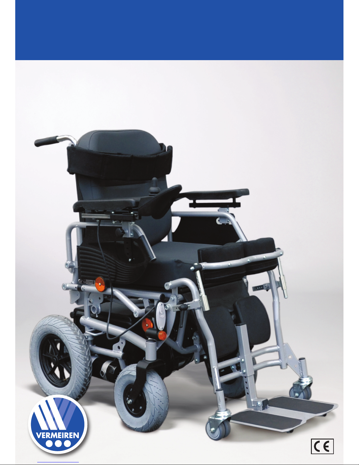
SHARK 2 CONTROLS
The control unit built into your electric wheelchair enables you to manage all the vehicle's driving,
steering, braking and operating procedures. The wheelchair's electrical unit and electronics are
constantly being monitored internally. Any fault in the electronics is indicated on the steering unit and,
if necessary, the wheelchair is switched off for reasons of safety (see the "Error codes" section).
Press the "ON/OFF" button (1). The charge indicator (2), which also indicates the batteries' charge
level, lights up for a moment. If all the lights come on, the batteries are sufficiently charged. If the lights
do not all come on, you must adjust your driving activities to suit the low capacity of the batteries. If the
battery charger display lights do not come on, check the plug connections of the electronic system.
Now select the driving program you want by pressing the “Tortoise” (3) or “Hare” (4) buttons.
The selected speed can be set on the 5-level speed indicator (5). If you have any special needs, you
can ask your dealer to enter a personalised driving program.
To set the wheelchair in motion, push the joystick forwards slowly. The speed will increase when you
push the joystick further forwards. If you want to turn left or right, simply push the joystick in the
desired direction. To reverse, pull the joystick backwards from the central position.
1 = On/Off button
2 = Battery charge indicator
3 = Reduce speed (“Tortoise” symbol)
4 = Increase speed (“Hare” symbol)
5 = Speed indicator
6 = Left indicator light
7 = Right indicator light
8 = Seated/standing function
9 = Horn
10 = Hazard warning lights
11 = Lights
12 = Service indicator (fault analysis)
5 2 1 8 9 4 6 7 3
11
12
10
E
SQUOD_SU
06/2009
5
L Note that, when pressing the "ON/OFF" button, the joystick stays in the central position for at
least two seconds. It is programmed this way for technical and safety reasons, to prevent the
joystick being pushed at the same time as the wheelchair is being switched on. If both
processes are activated at the same time, the steering unit locks itself and can only become
operational again after being switched off completely.
Press the “Left indicator” (6) or “Right indicator” buttons to signal a change in your driving direction.
The driving lights are switched on or off by pressing the “Lights” (11) button. You can sound an
acoustic warning signal with the “Horn” (9) button. The hazard warning lights, used in critical
situations, can be switched on or off by pressing the “Hazard warning lights” (10) button.
To brake while driving, simply push the joystick to its central position. Move the joystick slowly for
gradual braking. Simply release the lever for a quick stop; the wheelchair will then stop as quickly as
possible.
To work the actuator for the standing/upright function, select button 8 and you can use the joystick to
move standing/upright function in the direction you want.
L Only use the standing/upright function in the presence of another person.
L Only use the standing/upright function if your legs and upper body have been secured
beforehand (see the "Chest belt" and "Leg support" sections).
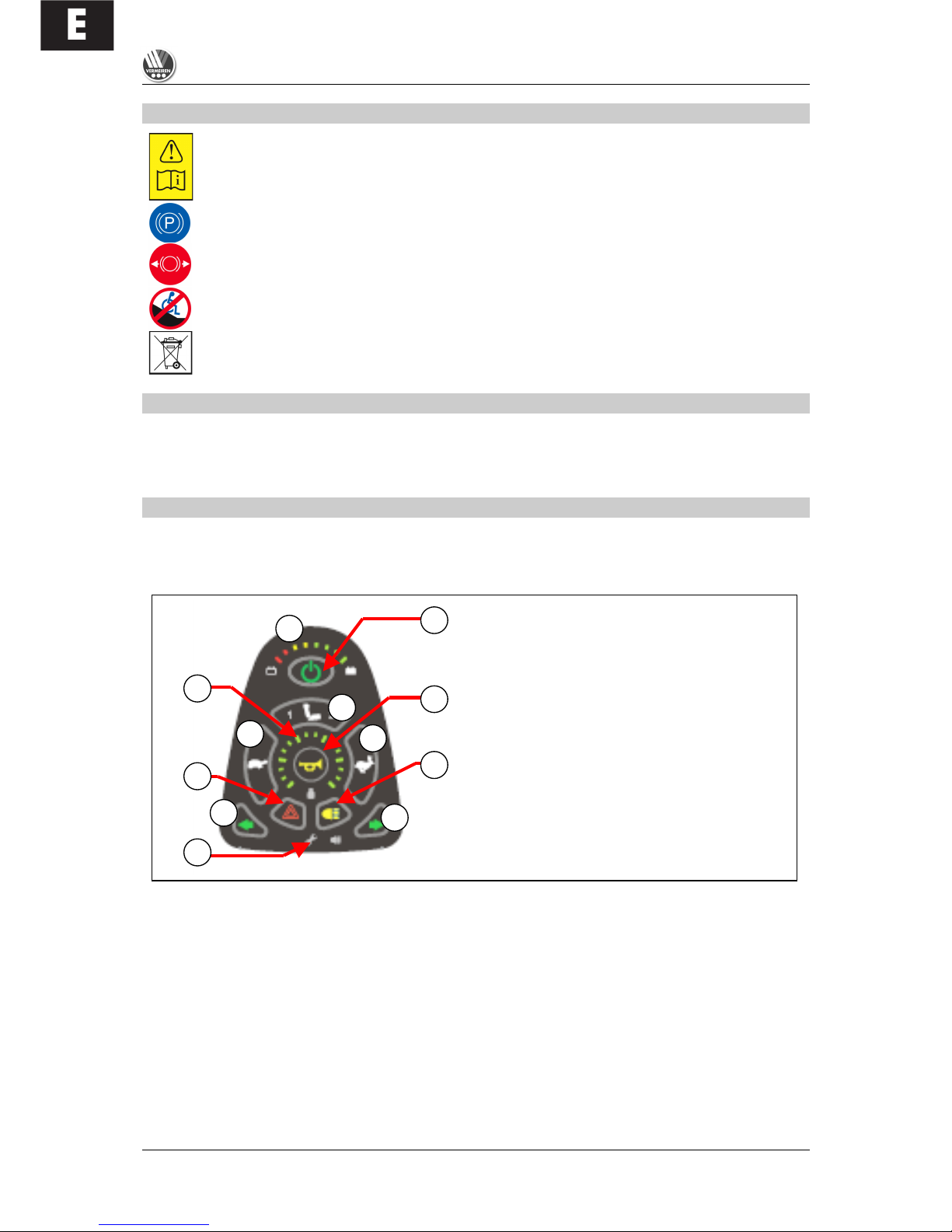
CONNECTIONS FOR CHARGER / PROGRAMMING UNIT
The socket for connecting the charger supplied is located on the front of
the control unit. Here, too, is the connnection for the programming unit,
which should only be connected and used by authorised persons who have
been trained to program it.
L Altering the drive parameters can adversely affect the
wheelchair's safety characteristics.
L
Make sure that all plugs (battery charger and programming unit) are removed before setting
the wheelchair in motion.
L Make sure that the steering lever is in the neutral (central) position when pressing the on/off
button, otherwise the electronics will be blocked. This block can be lifted by switching the
control unit off and then on again.
L Always adapt your speed to the prevailing environmental conditions.
If you wish to protect your wheelchair from unauthorised access, press the ON/OFF button (1) for
longer than two seconds when switching it off, and the control unit will lock. To unlock it, switch the
control unit on. For 10 seconds a progress indicator will appear in the load indicator. If you press the
horn (9) twice while this progress indicator is showing, the drive electronics will be unlocked and made
operational.
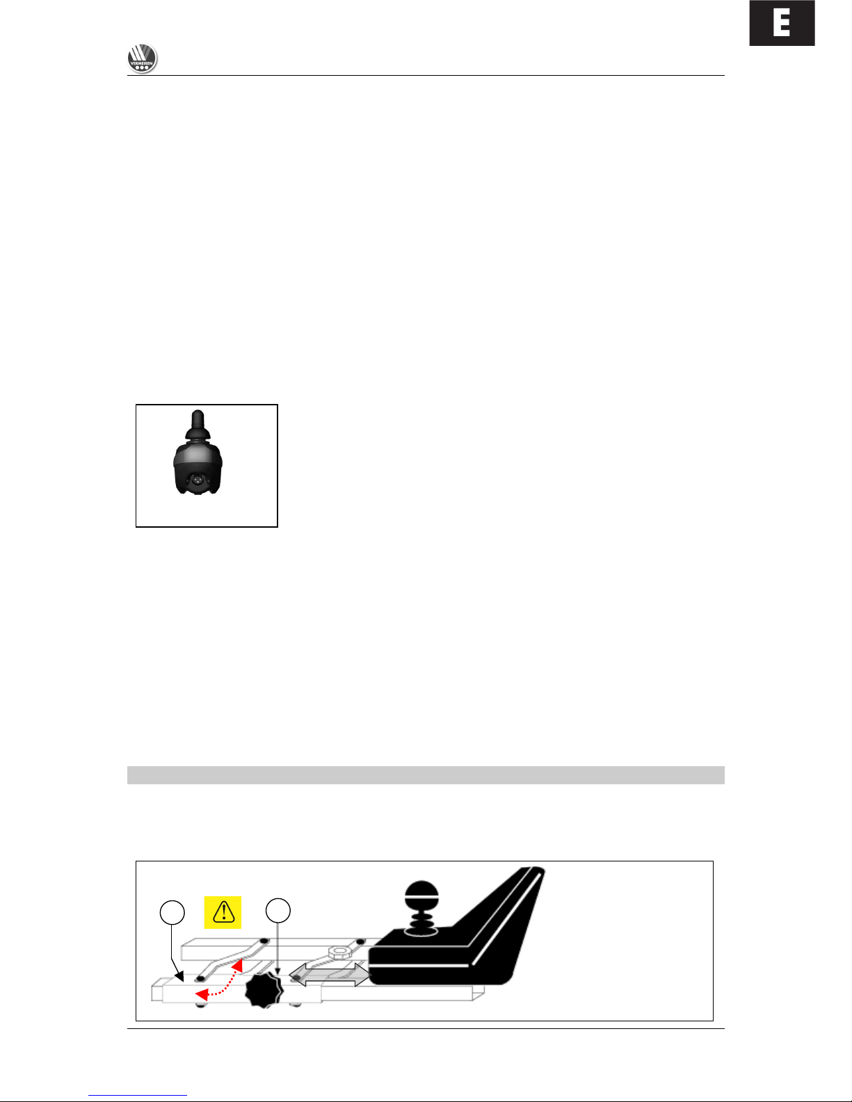
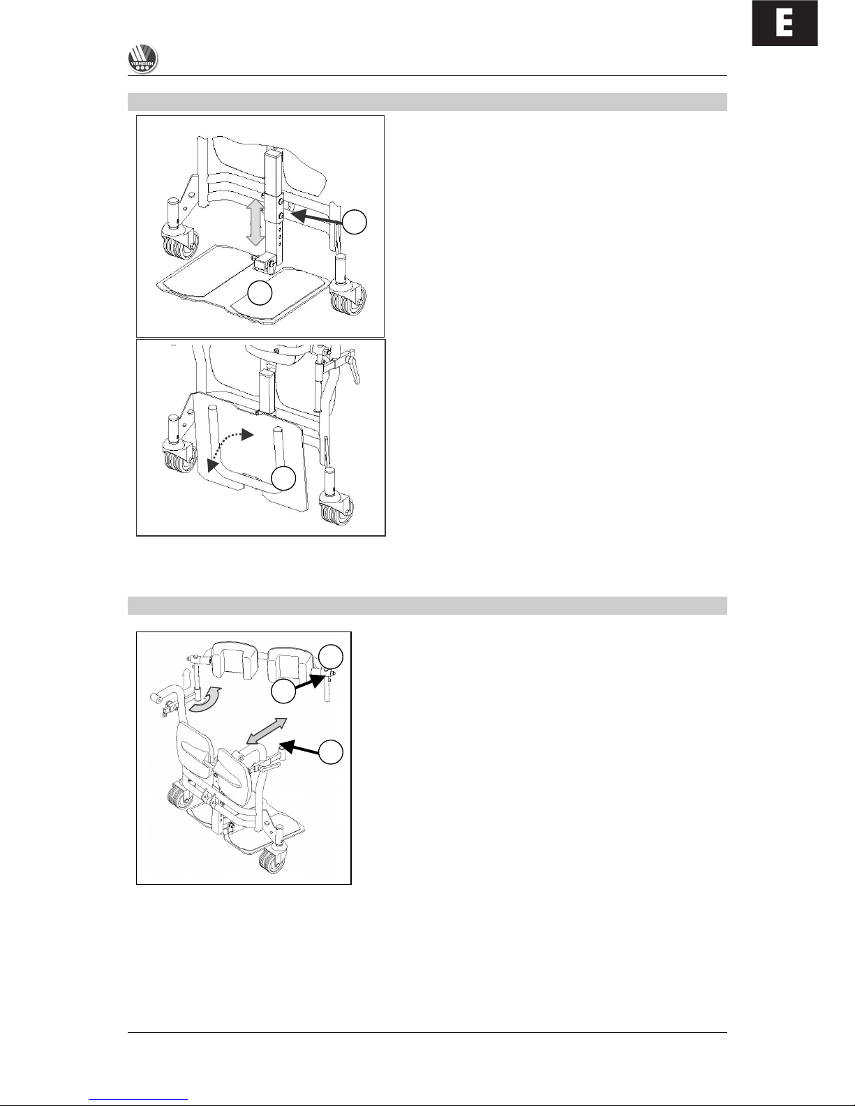
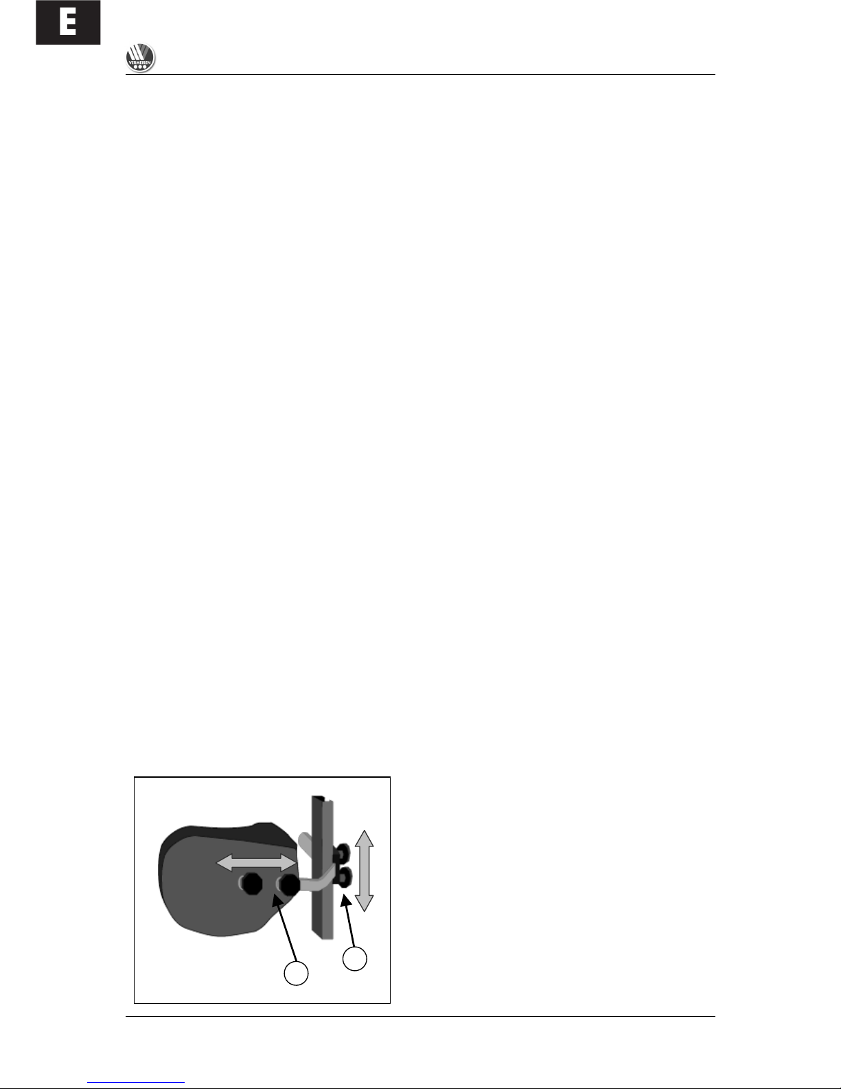
ADJUSTING THE STEERING UNIT
The steering unit's horizontal position can be changed by loosening screw (1). The unit can then be
adjusted as desired, or removed. Screw (1) must then be retightened properly. If screw (1) is pulled to
the side, the steering unit can be turned to the side.
NOTE: Depending on the features of your wheelchair, screw (1) could also be located beneath the
guide tube (2).
1
2
E
SQUOD_SU
06/2009
6
L When moving the control unit to one side, ensure that no objects or body parts are within the
range of adjustment, as there is risk that they could get caught!
BACK
The fixed back section is designed to be detachable. Loosen
the screws (1) and lift the cushioned back section up and out
of the retainers. To put it back in, place the back section
between the rear tubes in such a way that the back retainers
(1) are replaced into the retainers. Tighten these retainers
back up manually.
Before using, check that the back is properly fixed to the back
tubing (1). If it is loose, retighten the safety screws (1) which
secure the back to the back tubing.
L Before using the wheelchair, check that the fixing screws (1) are properly tightened, otherwise
the back might come loose, damage the chair and hurt the user.
L Make sure that no extra loads are hung from the back (e.g. rucksack, etc.) which might
increase the danger of tipping over backwards.
If the functioning of the back or some of its components has deteriorated because of wear and tear or
other causes, kindly consult your dealer. He/she shall gladly assist you further.
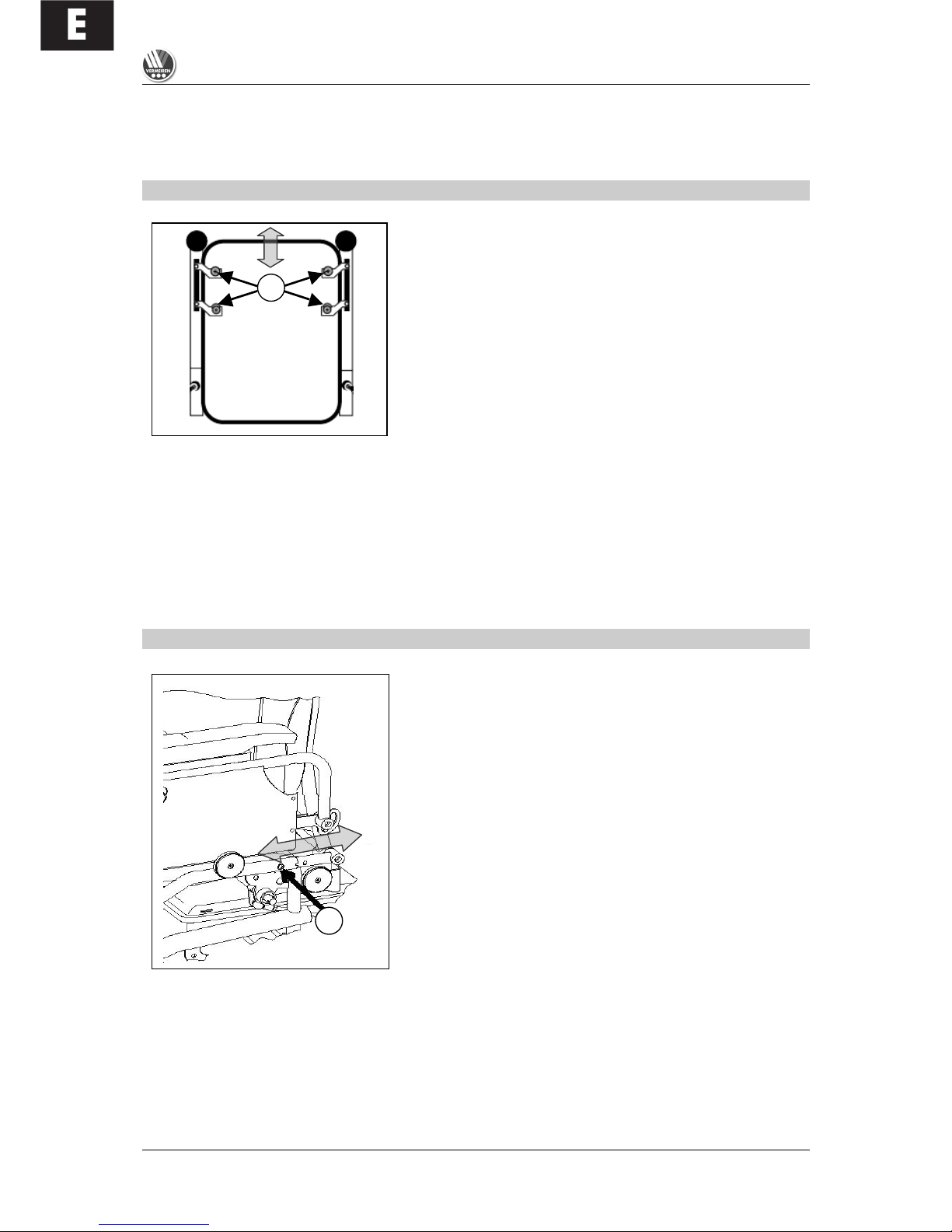
ADJUSTING THE DEPTH OF THE SEAT
The seat depth is adjusted by pushing the rear frame into
different positions. To do this, loosen the screw (1) on either
side of the frame and pull the rear frame out or in until it is in
the position you want, and until the relevant holes lie above
one another so that the fixing screws (1) can be inserted
through the frame. Hand-tighten the screws back up with the
nuts you previously loosened.
L The seat depth should never be changed when the
user is sitting in the wheelchair.
L Before using the wheelchair, check that the fixing
screws (1) on either side of the frame are properly
tightened, otherwise the back might come loose,
damage the chair and hurt the user.
1
1
E
SQUOD_SU
06/2009
7
LEG SUPPORT
The leg support consists of a one-piece footplate
whose height can be adjusted.
Loosen the screw connections (1) and pull the screws
all the way out of the bracket. Move the footplate to
the position you want and re-tighten it again with the
screws (1).
L Make sure that the leg support is tightly
screwed before use.
The footplate (2) can be folded upwards and
downwards.
L Never grasp the wheelchair by the leg support
in order to move it. Only grasp fixed parts of
the frame (see also the section "For your
safety".)
L Make sure that the footplate is at least 6 cm
above the ground to avoid scraping the
ground when moving. This could damage the
wheelchair and endanger its operational
safety. The patient could also get hurt.
L
Get an authorised person to adjust the leg support.
KNEE PROTECTOR
The knee protector should always be used for the standing/upright function.
Loosen the T-screws (1) on either side of the leg support and
pull out the retainer they secure as far as you can.
Put the leg bracket (2) with the knee pads with their vertical
struts on either side into the retainers provided.
L The mountings and knee pads are movable, and they
only fix in place when they are screwed tight and there
is counter-pressure on the legs/knees.
Now press the leg bracket (2) against the patient's legs in
such a way that the knee pads are pressed beneath the
kneecaps.
L Do not restrict the knees' range of movement!
There are screws in the vertical mountings (3) that you can use to adjust the height of the leg bracket.
When the leg bracket is in the position you want, re-tighten the leg/knee bracket with the T-screws (1).
2 1
2
3 1
2
E
SQUOD_SU
06/2009
8
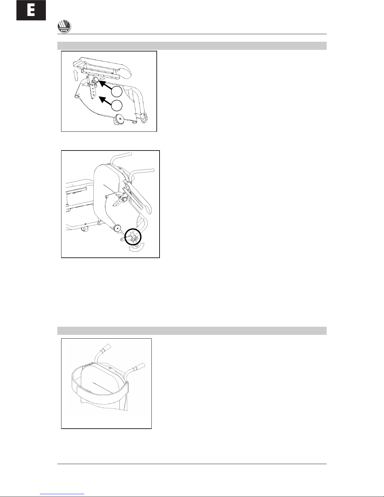
ARMRESTS
The height of the arm rests can be adjusted and they can also
be detached (e.g. so that the patient can be moved sideways).
Loosen the adjustable screw (1) a little and then pull it out.
The armrest can now be put into the position you want. The
adjustable screw (1) must then be replaced in one of the holes
in the plate (2) and hand-tightened.
L Make sure that all fixing screws are properly tightened
before using the wheelchair, otherwise injury and/or
damage can be caused.
The armrests can be folded back for therapeutic purposes and to move the patient from the
wheelchair.
Raise the armrests and fold them back if they are not needed
when the patient is being moved from the wheelchair or for
therapeutic purposes.
L The armrests may only be folded back when there
is no chance of the wheelchair user falling out
sideways.
L The screws on the folding mechanism (see circle)
must always be fastened tightly enough so that the
armrest cannot fall back down accidentally.
L To avoid endangering your safety, do not use the
wheelchair if you see that the mountings have
changed, been damaged, or have worn out.
L If you make any changes to the armrests and/or the armrest retainers, you do so entirely at
your own risk. Your guarantee will be voided.
L When you are folding down the armrests, ensure that no objects or body parts come within the
range that the armrest is swinging, as this could cause damage or injury.
L If you notice changes, damage, or wear to the mountins, please contact your dealer, who can
remedy these defects.
CHEST BELT
A chest belt is attached to the upper part of the back section
to secure the user during the standing/upright function. Place
the chest belt straps on top of one another and press them
tightly. The chest belt is made secure by an adhesive system.
L Attach the chest belt in such a way that the upper
body is pressed against the back section so that the
upper body cannot move involuntarily.
L The chest belt should not restrain the user's arms.
L As using the chest belt can restrict breathing, the patient must agree to the use of the chest
belt.
1
2

E
SQUOD_SU
06/2009
9
STANDING/UPRIGHT FUNCTION
To use the standing/upright function, you must always ensure beforehand that the legs are made
secure with the knee brackets and the upper body likewise with the chest belt (see descriptions in the
relevant sections, "Leg support" and "Chest belt").
L The standing/upright function must only ever be used when another person is supervising.
L The standing/upright function may not be used without the chest belt and knee protector being
secured - this would be done at your own risk.
L The manufacturer accepts no liability for use of the standing/upright function without the chest
belt and knee protector .
L The standing/upright function may only be used if all four of the wheelchair's wheels are in
contact with a level surface (and while being used on the two front wheels).
L Make sure that no objects, persons or body parts are inside the movement range of the
upright function, since this could cause damage or injury.
L Ensure that the steering cables do not get caught during the upright function, as this could
damage the product.
Follow this sequence when using the standing/upright function:
1. Adjust to the position you want.
2. Ensure that the wheelchair is stable. If necessary move it to the position you want.
3. Switch off the drive electronics.
4. Deploy the knee protector (or have it deployed for you).
5. Check that the feet are resting flat on the footplate.
6. Deploy the chest belt (or have it deployed for you).
7. Check whether the arm rests are folded down.
8. Switch on the drive electronics and select the adjust function for the upright function.
9. Pull the joystick backwards or push it forwards to carry out the relevant function.
Bear in mind that, when the upright function is
in use, the wheelchair rests on the front rollers
beneath the footplate and the steering wheels
(200x85) lift about 1 cm from the ground. To
change direction, the wheelchair is then
moved using the rollers and the drive wheels.
There is only limited drive functionality.
L Only loosen the chest belt and the
knee protector again when the
wheelchair has been returned to the
seated position.
L The standing/upright function must
only ever be used when another
person is supervising
L The standing/upright function may not
be used without the chest belt and
knee protector being secured - this
would be done at your own risk.
L
The manufacturer accepts no liability for use of the standing/upright function without the chest
belt and knee protector .
L The standing/upright function may only be used if all four of the wheelchair's wheels are in
contact with a level surface (and while being used on the two front wheels).
L
L
L

E
SQUOD_SU
06/2009
10
L Make sure that no objects, persons or body parts are inside the movement range of the
upright function, since this could cause damage or injury.
BATTERY CHARGER
To charge the batteries, only use the battery charger supplied - IMPULSE S (8 A).
Primary voltage
230 Vac – 50/60 Hz – single phase
Secondary nominal voltage
24 V
Secondary maximum voltage
35 V
Secondary power
max. 8 A
Battery type
Lead-sulphuric acid: gel
Battery capacity
60 Ah – 85 Ah (80% capacity charged within 8 hours)
Safeguards
Protected against reverse polarisation, electrical
surges and extreme temperature
Nominal output
270 W
Efficiency
min. 80% (when fully loaded)
Ambient temperature
0° C to +40° C
Unit dimensions
H 70 x W 150 x D 200 mm
Protection range
IP 21, Protection Class II
Total weight
Approx. 1.3 kg
Mains cable length
1.9 m
Charge cable length
2.4 m
Ambient storage temperature
-15° C to +50° C
Relative storage humidity
max. 95% (non-condensing)
Conformity
EMC Directive 89/336/EEC
Low Voltage Directive 73/23/EEC
We reserve the right to introduce technical changes.
CHARGING THE BATTERIES
As the IMPULSE S (8 A) charger aligns the charge curve with the AGM batteries' charge level, you
can recharge your wheelchair after each use. This avoids any aggressive battery charging and the
"memory effect".
Recharge the wheelchair, at the latest, when the charge indicator on the steering unit goes into the red
zone. If, despite this, you continue driving, eventually only the last red diode lights up and flashes
continually, indicating that the batteries are nearly flat. If you disregard this warning signal, too, an
error message will shortly appear indicating that the batteries can no longer provide power for driving.
The batteries should therefore be charged before these error messages appear, using the supplied
battery charger IMPULSE S (8 A). Avoid the batteries becoming drained, in any case.
• SETTING UP THE CHARGER
When setting up the charger, ensure that it is well-ventilated on all sides. A minimum of 10 cm space
should be left free around the unit for this purpose. If the charger is insufficiently ventilated so that the
unit heats up, the charging rate will fall which will extend the charging time. If the charger overheats (>
+50° C), it will stop charging.
The charger should only be used from a wall socket with a voltage of 230V – 50/60Hz and in wellventilated, dry areas.
• FIRST USE
First put the plug into the wall socket. After an LED combination has lit up, the charger switches to
STANDBY. Both LEDs (green and yellow) are active.
Next, connect the charger cable with the three-pin plug to the loader socket on the electric
wheelchair's steering unit. Once connected to the batteries, the charger automatically begins charging.
Now only the yellow LED is active.
When charging is complete, the yellow LED goes out and the green LED comes on. Now remove the
charger cable from the steering unit. The charger switches back to STAND-BY mode (yellow and
green LEDs active).
E
SQUOD_SU
06/2009
11
If the charger cable is not removed, a tiny current will keep the batteries topped up (trickle charging).
L When charging is complete, always remove the plug from the steering unit first and only then
the mains plug from the wall socket.
• CHARGER DISPLAYS
Yellow LED
Green LED
Charger switched off (not plugged into the mains)
!
!
"
!
Charger has just been switched on and displays the
charging characteristic that has been set
!
"
Stand-by
#
#
Charging
#
!
Full
!
#
Fault
"
"
! = Off # = On " = Flashing
L If the batteries are not used for an appreciable period, they discharge slowly by themselves
(drainage). Then it becomes impossible to recharge them with the battery charger supplied.
So charge the batteries at least once a month even if they are not being used.
L Only use the battery charger supplied to charge the batteries.
L The manufacturer accepts no liability for damage caused by improper charging.
L Never interrupt the loading cycle. The charger shows when the charging cycle is finished.
(green LED remains active).
For further information, please refer to the user instructions provided with the charger.
BATTERIES
The standard for your electric wheelchair is two closed, 12V/70Ah AGM batteries. The batteries used
with your electric wheelchair are drive batteries which only attain full capacity after a few charging and
use cycles.
If the batteries lose their power after long usage, or if they are damaged, get them both replaced by a
specialist dealer only.
L We accept no liability for damage caused through using other types of battery.
L Do not use the batteries at temperatures below +5°C or above +50°C (the ideal is: +20°C).
L If the batteries are opened, all manufacturer liability and all claims will become void.
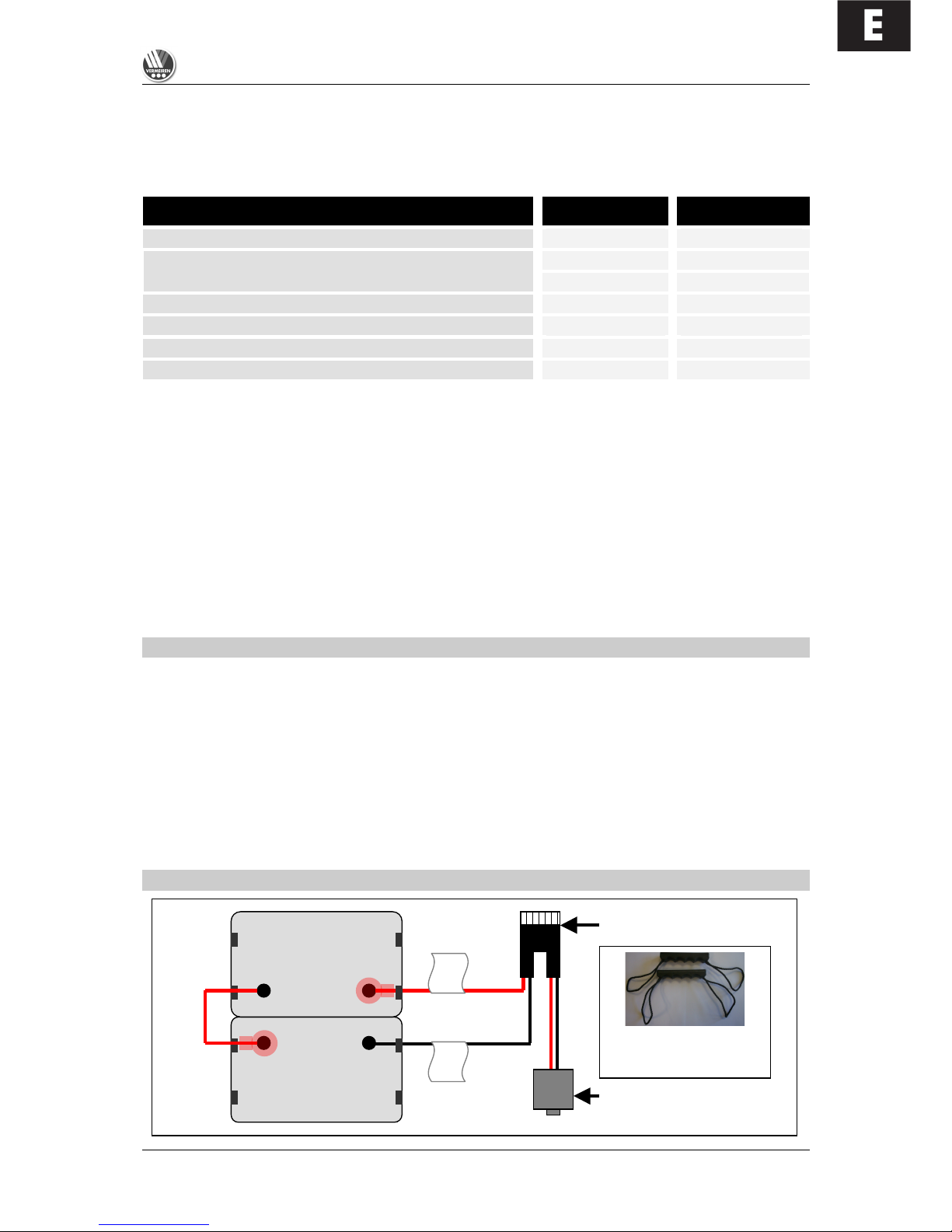
BATTERY CONNECTIONS
+
+
-
-
Red
Black
Re
Thermal fuses
24 V
30 A
Power module plug
Carry handles for batteries
(each attached to the side
notches on the batteries)
E
SQUOD_SU
06/2009
12
BATTERY STORAGE
If you no longer use your wheelchair, you can leave it connected to the battery charger. Charging is
automatically controlled by the battery charger. If you remove and store the batteries, kindly note the
following:
• Remove the cable clamps from the poles of the battery.
• The positive pole must be covered by at least one pole cap.
• Only grasp the batteries by two opposite sides of the unit.
• Make sure that no objects make contact with both poles during storage (danger of short circuits!).
• Batteries should only be stored in dry, well-ventilated spaces at a temperature between 0°C and
+40°C.
• Keep the batteries in the battery boxes for protection against damp or other external influences.
• Protect the plugs and sockets of the battery boxes against corrosion.
• Protect the batteries against drainage (see "Charging the batteries" section).
L If batteries are not used, they can completely drain.
If you have further questions, consult your dealer who will gladly advise you on storing and
maintaining your batteries.
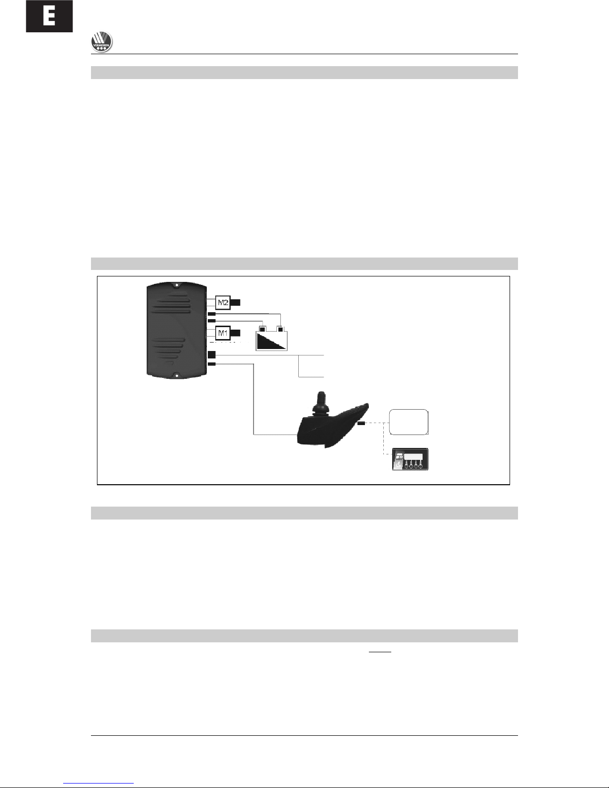
SYSTEM CONNECTION
THERMAL SAFETY MECHANISM
To protect the motor against overload, on the right side of the seat frame there is a thermal safety
mechanism (transition to the rear frame) that will automatically cut off the motor to prevent overheating
and thus rapid wear and tear or breakdowns. This can occur if you go up or down slopes that exceed
the maximum gradient indicated. Nominal loads exceeding the maximum could also trigger the safety
mechanism. If you try to drive with the brakes on, it could also result in overload. The values to comply
with are indicated in the “Technical Details” section. To be able to use the wheelchair again, remove
the overload and wait till the motor has cooled off, and then gently press in the thermal safety
mechanism again. The system is now ready for use again.
PARKING BRAKES
In addition to electromagnetic braking, your electric wheelchair could also be equipped with fixed
braking for each driving wheel. These must then be set for the wheels.
When pneumatic tyres are used, the parking brake can only function when the tyres are inflated hard
enough (see the section "Technical details").
L Note that the tyre pressure should always correspond to the values given in the section "Technical
details", otherwise the action of the parking brakes would be reduced or even be zero.
Left-hand motor
Right-hand motor
SHARK
power module
SHARK 2
control unit
Battery
charger
Programming
(PC-based or
hand-held device)
Light connections
Actuator
connection
(SHARK 2 only)
24 V battery
supply

E
SQUOD_SU
06/2009
13
L Note that the parking brakes are not supposed to be used for braking while driving. The real
function of the parking brakes is to prevent the wheelchair from rolling away after it has
stopped. If it is used for reducing the speed while driving, injury and/or damage could result.
If the brakes lose their function through wear and tear and/or the covers and hoses have been
damaged, we advise you to consult your specialist dealer who has the tools and the knowledge for
repairing / replacing the defective parts.
L When unsuitable tools are used or through improper maintenance
damage and/or loss of function could result.
If you wish to adjust the parking brakes yourself, use a suitable Allen key to loosen the two screws
which hold the brake suspension on the rail. Then push the brake unit to the desired position and
retighten the two Allen screws and check whether the braking action is correct.
L Brake adjustments not complying with the manufacturer's instructions are done at your own
risk (only in the case of built-in parking brakes). No liability is applicable.
L Rather let your dealer adjust the parking brakes; he is trained on our products and will comply
with all relevant prescribed safety measures.
L Note that the parking brakes are not supposed to be used for braking while driving. The real
function of the parking brakes is to prevent the wheelchair from rolling away after it has
stopped. If it is used for reducing the driving speed, injuries could follow.
If you are not satisfied with the braking behaviour of your wheelchair, consult your specialist dealer
immediately; he will then adjust the brakes properly.
L If water, oil, or other kinds of dirt have soiled the wheels of the wheelchair, then the braking
action of the parking brakes would be impaired. Check the condition of the wheels every time
before using the wheelchair.
L If the brakes lose their effectiveness because of wear and tear and/or damage to the
tyres/inner tubes, kindly consult your specialist dealer, since special machines are required for
changing the tyres. The end user should not change the wheels themselves.
TYRES
The SQUOD SU electric wheelchair is fitted with 3.00-8 driving wheels (pneumatic) and 260x85
steering wheels (pneumatic). Consult your specialist dealer about other wheel combinations. He will
advise you as to which combinations are suitable for your individual requirements.
L Make sure that the wheels are always inflated correctly, otherwise the driving behaviour might
be affected. The correct pressures for the tyres are given in the chapter "Technical details". In
addition, you should always check the pressure values appearing on the tyres themselves.
L We do not provide any guarantee for wheels not supplied by the manufacturer.
E
SQUOD_SU
06/2009
14
TYRE CHANGING
If you want to change the tyres or inner tubes, you should note the following:
STEERING WHEELS
A. Loosen the screw on the steering wheel axle and
remove it from the steering wheel fork.
B. Let the air out of the steering wheel by lightly pressing
the pressure pin on the valve.
C. Loosen the 5 screws that hold the split rim together.
Now separate the rim sides.
ASSEMBLY
Insert the partly-filled inner tube into the tyre.
C. Connect the two sides of the rim through the tyres and
use the 5 connecting screws to screw the rim
together.
B. Make sure that the valve juts out of the valve opening
in the rim.
A. Put the wheel back into the front wheel fork and inflate
the wheel.
L Before taking the rim apart always let the air out of the tyres, or the sides of the rim could
come apart explosively and cause injury!
L Make sure that the inner tube does not get caught in the sides of the rim
L Only inflate the wheels to the max. tyre pressure (see "Technical details")
L Check to see that all the screws on the wheels are firmly tightened before using the
wheelchair.
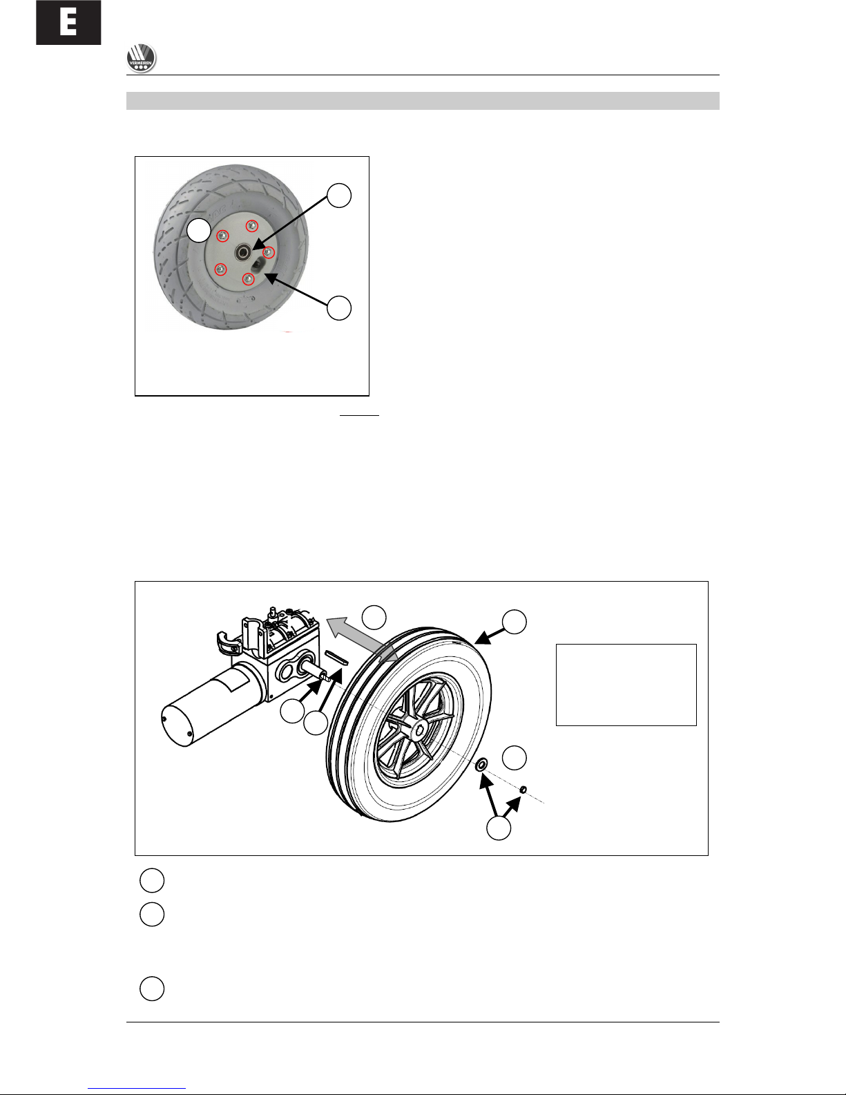
DRIVE WHEELS
The drive wheels can be detached from the drive motor.
Loosen and remove the wheel nuts (4).
Completely detach the wheel (3) from the motor axle (1).
The groove pin (2) that rests on the motor axle can get jammed in the rim.
WHEEL ASSEMBLY
Remove dirt from the thread and axle of the wheel mount on the motor and degrease the
thread.
A
B
C A B
1
A B 1
2
3
4
1 = Motor axle
2 = Groove pin
3 = Wheel
4 = Wheel nuts
E
SQUOD_SU
06/2009
15
Place the groove pin into the motor axle recess (1).
Pull the wheel over the motor axle (1) to the stopping point (avoid poor alignment). In doing
this, ensure that the recess on the rim hub fits over the groove pin (2).
Hand-tighten the washer and screw (thread locker can be used to secure it).
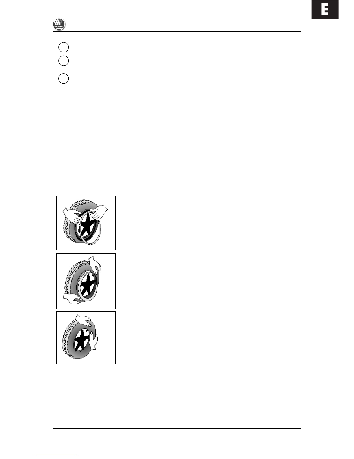
Before you can remove a tyre, you must let all the air out of the tube, and insert a tyre lever between
the tyre and the rim. Then slowly and carefully push the lever downwards. This will pull the tyre over
the edge of the rim. If you then move the lever along the rim, the tyre will jump out. Now carefully
remove the tyre from the rim and then remove the tube.
L There must be no air in the tube before it can be removed.
L If handled improperly, the rim might be damaged. These procedures should only be
undertaken by authorised individuals.
Note the following before inserting the new inner tube:
Check the rim bed and the inside wall of the tyre for foreign matter and clean these properly if
necessary. Check the condition of the rim bed, especially around the position of the air valve. Please
use only genuine original replacement parts. We do not accept any liability for damage caused by nongenuine parts. Kindly contact your specialist dealer.
Assembly:
Place the rim belt in position over the air valve before inserting it into
the rim. Then the rim belt can be pulled over easily. Check whether
all spoke heads are covered (in the case of a plastic rim a rim belt is
not required).
Push the tyre over the edge of the rim, starting behind the air valve.
Inflate the tube slightly until it is round, and place it inside the tyre.
If the inner tube fits snugly inside the tyre without any folds (if there
are folds, let some air out), then you can push the upper side of the
tyre gently onto the rim with both hands, beginning behind the
airvalve.
Check all around on both sides that the tube is not pinched between the rim and the edge of the tyre.
Lightly push the air valve inwards and pull it out again to make sure that the tyre is positioned properly
in the region of the air valve.
To ensure that the wheel is inflated correctly, admit only so much air initially that the tyre can still be
easily pushed inwards by using your thumbs. If the check-lines are equidistant from the edge of the
2 3 4
E
SQUOD_SU
06/2009
16
rim on both sides of the tyre, then the tyre is centered properly. If not - let out the air and position the
tyre afresh.
Now the tyre can be inflated to its full operating pressure (note the maximum) and the valve cap
should be replaced.
If changing the wheel, ensure that the motor's axle thread has been cleaned before it is tightened with
the wheel screw. If the nut is being replaced, a new, self-locking, orginal nut should be used.
L Check that no objects or body parts are caught between the tyre and the edge of the rim,
since it could cause damage or injury.
L Improper assembly voids any warranty claim.
L When inflating the tyres, always check that the pressure is correct. The correct pressure is
given on the tyre walls (also refer to "Technical details").
L Use only inflating equipment which complies with regulations and indicates the pressure in
bar, or use the supplied air pump. We do not accept any liability for damage caused by using
inflation equipment not supplied by the manufacturer.
PUSHING THE WHEELCHAIR
The wheelchair can be pushed by an attendant.
When pushed, the operating
equipment is switched off, and the
wheelchair can only be pushed on
level terrain. Without the braking
action of the motors the occupant is
exposed to considerable danger
when the wheelchair is pushed
along on a gradient. This must be
avoided.
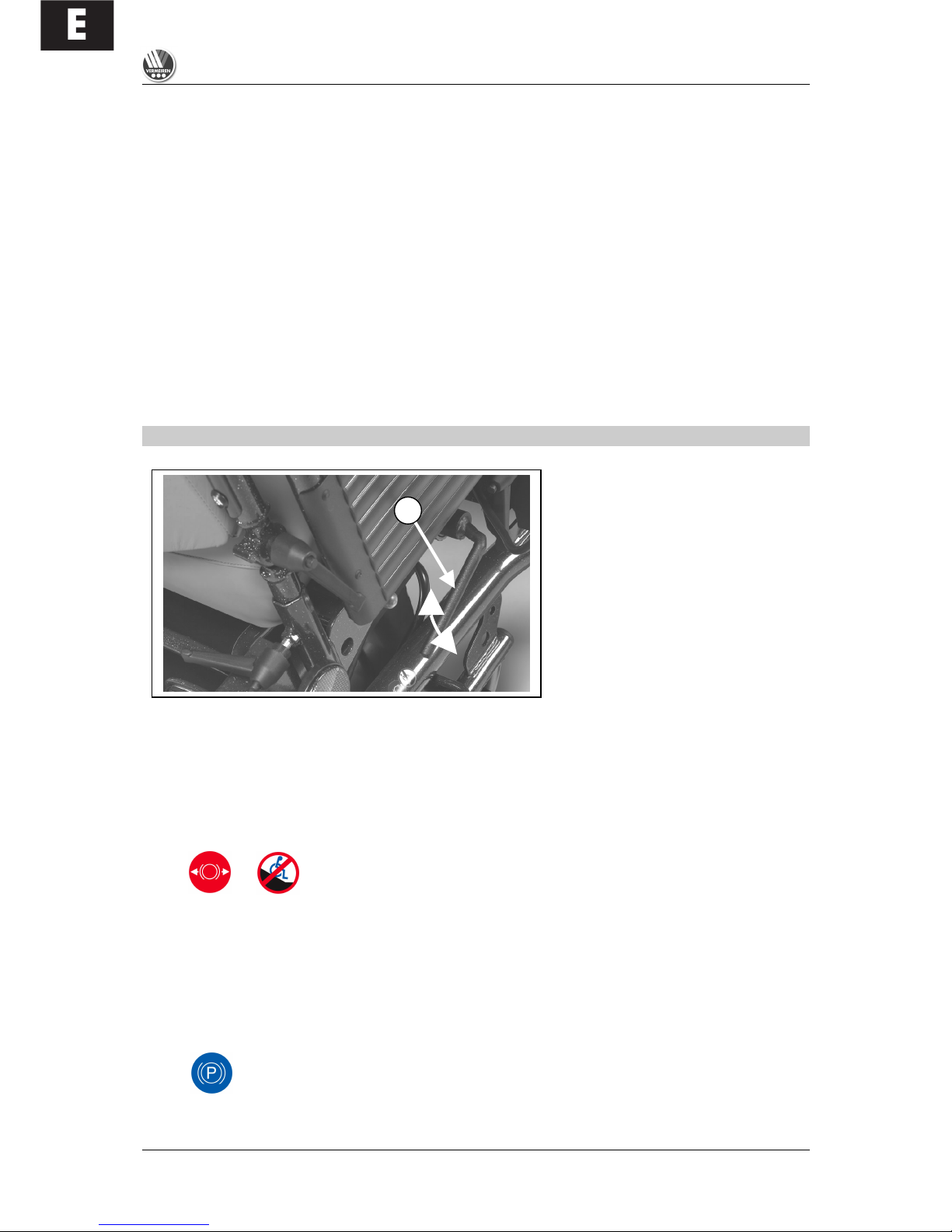
On the right hand side of the wheelchair, there is a tilt lever (1) that ends the manual free running
mode and enables electronic driving.
NEUTRAL
Gently pull the lever (1) outwards and then push it down. This separates the motor from the gears and
allows manual pushing of the wheelchair.
L In free running mode, the electronic brake is deactivated and the wheelchair will no longer be
held back. Do not activate free running mode on slopes. Activate the parking brakes.
ELECTRONIC DRIVING
Pull up the lever (1) to link the gears to the motor.
L This activates the electromagnetic parking brakes. Release the mechanical parking brakes to
enable electronic driving.
L If your wheelchair performs involuntary movements in free running mode, pull up the tilting
lever for an EMERGENCY STOP.
1
E
SQUOD_SU
06/2009
17
TRANSPORTING THE WHEELCHAIR
If your SQUOD SU is to be transported, please note the following:
Before lifting up the wheelchair, all moveable parts must be dismantled.
L Before moving the wheelchair, the seat/back unit should be moved to the seated position.
L When raising the wheelchair, it should only be grasped by fixed parts of the frame.
L To avoid damage, remove the steering unit and knee protector before transporting it.
L When assembling, make sure that all screws are retightened properly.
To prevent the wheelchair from moving about, switch the locking mechanism to electronic driving
(activation of the electromagnetic parking brakes). In addition, engage the parking brakes if present in
your model. If you require further belt securing systems, make sure that they are only attached to solid
parts of the frame.
L At least two persons are required for moving it up or down on a staircase or over single steps.
L When being transported, no persons or objects should be below the wheelchair, to prevent
personal injury or damage to the wheelchair.
L The wheelchair should not be transported while the patient is seated in it.
USING RAMPS
If you are considering ramps for overcoming obstacles, kindly note the following:
The seat/back system must be moved to the seated position beforehand. The drive program should
not be used during the standing/upright function. For your safety you should drive at the slowest
possible speed on ramps.
If another person is pushing you, note that the large weight of the electric wheelchair exerts
appreciable reverse forces.
If your helper does not have the strength to push the wheelchair up the ramp, you must immediately
secure it by engaging the electronic parking brakes (EMERGENCY STOP).
L Observe the instructions on the maximum load of the ramps used.
L Use a restraining safety belt to secure yourself in your wheelchair.
L We do not accept any liability for injury or damage caused by an improper choice of ramps.
ACCESSORIES
! INDIVIDUAL HEADREST (L55)
The standard backrest can be enhanced by an individually adjustable head support supplied by us.
This comprises a cushioned headrest which can be set in various positions by means of a gearwheel
(see diagram).
The receptacle screwed in the upper third of the back, can be fixed to the centre of the back for
inserting the headrest. The height of the headrest can be adjusted and then tightened at the desired
height. The holes required for fixing the headrest have already been drilled in the back unit.
E
SQUOD_SU
06/2009
18
L Make sure that the headrest is inserted at least to the marked position to be fixed securely and
reliably.
The depth of the headrest can be adjusted by slightly loosening the adjusting screws to allow
movement of the sprocket gears. Then you can adjust the headrest to your needs and secure it by
retightening the adjusting screws. If the adjusted position is not satisfactory, you can repeat this
process.
L Ensure that the back of your head is supported when relaxed in an upright sitting position.
L Before using the headrest all fixing screws must be tightened properly, since injuries might
result when it slips downwards unintentionally.
You can secure your head against tipping sideways by lightly pressing the side panels of the headrest
inwards and to the front.
L Do not exert too much pressure on the side panels otherwise bruising may result.
L Do not clap the side panels together violently, otherwise they might break off, causing possible
injury as well as loss of function.
Structural alterations of the headrest would void any warranty.
! PERSONAL SAFETY SYSTEM (B58)
For your safety we offer you a standardised safety belt which is equipped with a snap-on fastener, like
those mounted in cars and vans. This can be fixed by means of bolts inserted in the bolt holes on both
sides of the seat frame next to the backframe attachments. To ensure proper fixing, self-locking
("nylock") nuts should be used.
If the belt has been dismantled, only new genuine nuts provided by the manufacturer should be used
for re-attachment.
L To ensure the validity of the warranty, entrust this work to your specialist dealer.
L Before using the seatbelt, make sure that all screws are properly tightened.
Please consult your specialist dealer if you require other safety belt systems. He/she shall gladly
assist you further.
! ANTI-TIPPING DEVICE (B78)
For your safety your electric wheelchair is equipped with an anti-tipping device. Do not remove this or
your wheelchair will no longer be secured against accidentally tipping over.
L Before driving off, make sure that the anti-tipping device is inserted on both sides and securely
fastened.
L Always, before driving off, ascertain that the tipping protector is mounted in such a way that its
rollers bear on the ground to prevent toppling further over backwards in the event of
unintentional tipping.
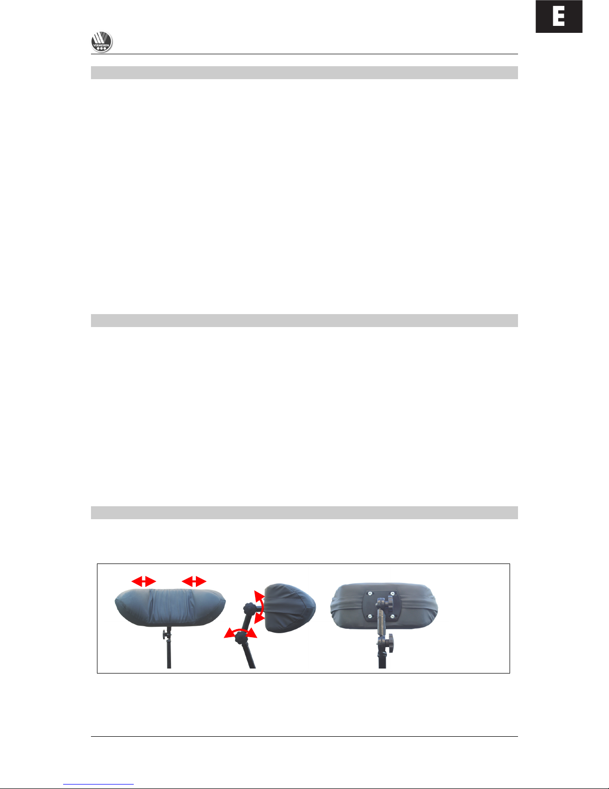
! BODY SUPPORTS (L04)
If your upper body requires stronger bracing than that
provided by the standard backrest, we offer a lateral
support system which can be mounted on the
backrest. The guiding rail is mounted vertically about
6 cm behind the backrest to one side. The screw
threads set in the back are to be used for this purpose
The supporting rods are inserted from the rear and
secured by the two Phillips screws. When adjusting
the height and depth of the "pelotten", slightly loosen
the Philips screws (1) and place the "pelotten" in the
desired position. Then retighten the Philips screws
(1).
1
2

E
SQUOD_SU
06/2009
19
To adjust the depth of the "pelotten", you can loosen screws (2) and set the "pelotten" to the desired
depth.
L Make sure that all screws are properly tightened after the assembly, otherwise the stability of
the "pelotten" is endangered, and this may cause injury and/or damage.
L Make sure that the rail system is properly mounted and that nothing obstructs its functional
integrity.
L If the wheelchair is not fully assembled when delivered, only your specialist dealer who has
suitable tools and knowledge of the fittings, may perform the mounting procedure.
L Improper assembly leading to damage voids any warranty claim.
L While the body supports are fitted, you should sit quietly and naturally in your wheelchair to
allow correct fitting.
L Make sure that no objects and/or body parts are located between the "pelotten" and the back
of the "pelotten" when these are pulled tight, otherwise bruising and/or damage might occur.
If you have further questions about the indications and function of the "pelotten", kindly contact your
specialist dealer. He would gladly answer your questions.
FOR YOUR SAFETY
Some safety tips are given below for your security:
L To prevent injury and/or damage to your wheelchair, make sure that no objects and/or body
parts are caught in the spokes of the driving wheels.
L Do not step on the footplate when entering or leaving the wheelchair. The footplate should be
folded up beforehand.
L You should investigate the effects of shifting the centre of gravity on the behaviour of the
wheelchair for example on gradients, on laterally sloping ground, or when overcoming
obstacles, only when a helper is present to secure and support you.
L If you want to pick up something (lying in front of, on the side, or to the rear of the wheelchair),
you should not lean too far out to avoid tipping over because of the displacement of the centre
of gravity.
L Only use your wheelchair according to regulations. Avoid for example driving without brakes
against an obstacle (step, edge of the curb) or driving down from ledges.
L If devices and furnishings like ramps or lifts are available, use them.
L Driving should only take place in the seated position. The drive program should not be used
during the standing/upright function. Reduced drive should be deployed only for altering
position during the standing/upright function.
L Only carry out the standing/upright function under supervision from another person, as the risk
of tipping increases when weight shifts in the wheelchair.
L The standing/upright function should only be used if the chest belt and leg/knee protector are
properly attached and deployed.
L Check that the profile depth of the tyres is adequate.
L Obey traffic regulations when driving on public roads.
L When driving your wheelchair, you should not be under the influence of alcohol or medicine as
in the case of driving other vehicles. This also applies to indoor driving.
L When travelling outdoors, adapt your driving to weather and traffic conditions.
L Check that the rear reflectors of your wheelchair are not covered by dirt and/or other objects.
L When driving in the dark, wear bright clothing to be more visible, or clothing with reflectors,
and make sure that the reflectors of the wheelchair are clearly visible.
L Be careful when using sources of fire such as cigarettes, since they can set the seat and back
covers alight.

E
SQUOD_SU
06/2009
20
L Make sure that the maximum load (130 kg) is not exceeded.
MAKING REGULAR CHECKS
As with any technical product, your wheelchair, too, requires regular checks if it is to be kept fullyfunctional. The steps to be taken to fully enjoy the advantages of your wheelchair even after protracted
use, are described below.
! BEFORE DRIVING
1. Check the tyres for visible damage and/or soiling. Remove any dirt as it could impair the
motion and road-holding capacity of the tyres. When a tyre is damaged, please go see an
authorized workshop for repair.
2. Use the drive electronics' display to check that the driving, braking and adjustment
features are fully-functional. If these functions are impaired, contact your dealer.
3. Check the pressure of the tyres and inflate them if necessary (see section "Technical
details").
4. Make sure that all screws are tightened properly (particularly: the folding armrest
mechanism so that they do not accidentally drop down forwards and cause injury.)
! APPROX. EVERY 8 WEEKS
Depending on the frequency of use check the following:
1. That the armrests are working
2. Movable parts of the footrests
3. The condition of the covers and cushioning materials.
4. The tread depth of the wheels
! APPROX. EVERY 6 MONTHS
Depending on the frequency of use check the following:
1. Cleanliness
2. General condition
3. That the charger is working
4. Operation of the steering wheels
If the rotation resistance is too large, clean the bearings of the steering wheels. If this is
insufficient, kindly consult your specialist dealer.
L In cases of lost functionality, repairs and inspections, consult your dealer. Only authorised
persons should do repairs.
INSPECTION
In principle we recommend annual inspections, but at least before usage is resumed. The following
checks must at least be performed and documented by authorized persons:
• Check the cabling (especially for: crushing, abrasion, cuts, visible insulation of the inner
conductor, visible metallic veins, kinks, lumpiness, color changes of the outer sleeve, brittle
spots)
• Visual inspection of the frame parts to check for plastic deformation and/or wear and tear
(basic frame, seat frame, back frame, side parts, leg supports, motor suspensions)
• Electric leads to be securely placed to avoid shearing, crushing and other mechanical stresses
and strains.
• Visually check all housings for damage, screws must be securely fixed, seals and gaskets
should not exhibit visible damage.
• Review the charger's residual diversion current (A) based on VDE 0702
• Review the charger's insulation resistance (MO) based on VDE 0702
• Check the functioning of the armrests and leg supports (locking, load, deformation, wear and
tear caused by loads)
• Check the functioning of the drives (during a test drive " noises, speed, free running, etc.), if
necessary: Measure the performance, first with no load, and then with the nominal load
("SWL") to investigate the wear and tear of the motors by comparing the values of the electric
current with the values at delivery, condition and function of the carbon rod.
• Check the condition of the batteries, covers, tubes, and tyres.
Checking measurements may only be carried out by skilled persons trained on the wheelchair at least
and at least under the supervision of an electrician who knows the checking instruments and

E
SQUOD_SU
06/2009
21
processes. Only an electrician is able to release the electric wheelchair for use after successful
checking measurements or servicing. The service must be confirmed in the service plan when at least
the above-mentioned aspects have been checked.
L The manufacturer is not liable for damage caused by lacking or improper service.
TOOLS
To repair individual components and accessory attachments, and to carry out inspections, the
following tools are the minimum required:
• Allen keys (sizes 3, 4, 5 and 6 mm)
• Fixed spanners/ring spanners (sizes 8, 10, 12, 13, 17 and 19 mm)
• Phillips screwdrivers (PH1, PH2)
L Any activities requiring these tools should only be carried out by authorised persons.
CARE
Your electric wheelchair requires regular care to keep it in a pleasant condition. To do this, note the
following:
L Steam or high-pressure cleaning is forbidden !
! COVERS
Clean the covers with hot water. You can remove stubborn dirt by washing with a mild commercial
detergent. Stains can be removed by using a sponge or a soft brush.
L Do not use strong cleaning liquids like solvents, nor use hard brushes.
L We shall decline all liability for damage caused by the use of improper cleaning agents.
L Take care that you do not soak the covers.
! PLASTIC PARTS
Clean all plastic parts of your wheelchair with commercial plastic cleaners. Read the specific product
information and only use soft sponges or cloths.
! SURFACE LAYERS
The high quality of the surface layer guarantees optimal protection against corrosion. If the outside of
the frame has been damaged by scratches or otherwise, you can protect the area by applying varnish
obtainable from your specialist dealer.
! ELECTRONICS CASING
Only wipe the steering unit with a cloth moistened
by a few drops of a commercial domestic cleaner.
Do not use any abrasives or sharp-edged polishing equipment like a metal scrubber or brush, since
these can scratch the surface of the steering unit and destroy its water repelling property.
L Regularly check the plug connectors for corrosion or damage, since it could affect the
efficiency of the electronics.
L Before any maintenance work, disconnect the batteries to prevent any unwanted current flow.
L The manufacturer accepts no liability for damage caused by poor maintenance.
STORAGE
• Store in a dry place (between + 5 °C and + 45 °C).
• The relative humidity of the air should be between 30% and 70%.
• Air pressure between 700 hPa and 1060 hPa.
• Disconnect the power plug of the battery charger.
• For the batteries, see the chapter on “Battery Storage”.
• Check internal cables for squashing and the prevention of kinks.
• Store all removed parts together in one place (or mark them if necessary) to avoid mixing up
with other products when re-assembling (e.g. the charger).
• Components must be stored without being subjected to any load. Grasp the wheelchair by
solid frame parts only.

E
SQUOD_SU
06/2009
22
DISINFECTION
Only a hygiene technician or someone appointed by him can disinfect your wheelchair and this should
be done every time before its use is resumed or before it is provided to a different person. All parts of
the wheelchair can be treated with a disinfectant cloth. In principle all surfaces of a system or a
product have to be disinfected before passing it on to another user, or when it is known that the user
carries an infective vector. In these cases the measures of the federal law on epidemics have to be
considered.
L Wear suitable protective clothing because the disinfectants can irritate the skin on contact. For
this purpose you should also take note of the product information for the solutions concerned.
L You employ unauthorized persons at your own risk.
L No liability is accepted by the manufacturer of the wheelchair for damage and injury caused by
the improper handling of disinfectants.
We recommend the following disinfectants for scrubbing (based on the list of the Robert Koch
Institute, RKI):
Surface
disinfection
(scrubwashing
Disinfecting excretions
1 part sputum or stool + 2 parts
diluted solution or 1 part urine + 1
part diluted solution
Washingdisinfection
disinfectio
n)
Sputum
Stools
Urine
Diluted solution
Time to take effect
Diluted solution
Time to take effect
Diluted solution
Time to take effect
Diluted solution
Time to take effect
Diluted solution
Time to take effect
Active substance
Name
%
Hrs. % Hrs. % Hrs. % Hrs. % Hrs.
Effectiv
e range
Manufacturer
or
Supplier
Amocid
1
12 5 6 5 4 5 6 5 2 A Lysoform
Gevisol
0,5
12 5 4 5 4 5 6 5 2 A Schülke & Mayr
Helipur 6 4 6 4 6 6 6 2 A B.Braun
m-cresol soap
solution DAB 6
1
12 5 4 A
Phenol or
phenol derivatives
Mucocit-F 2000
1
12 A Merz
Chloramine-T DAB
9
1,5
12
2,5 2 5 4 A1 B
Clorina
1,5
12
2,5 2 5 4 A1 B
Lysoform
Chlorine, organic or
inorganic substances
with active chlorine
Trichlorol
2
12 3 2 6 4
A1 B
Lysoform
Apesin AP1002
4 4 AB
Tana Professional
Pure Dismozon2
4 1 AB
Bode Chemie
Perform2 3 4
AB
Schülke & Mayr
Percompounds
Wofesteril2
2 4 AB
Kesla Pharma
Aldasan 2000
4 4 AB
Lysoform
Antifect FD 10
3 4
AB
Schülke & Mayr
Antiseptica
Surface
Disinfection 7
3 6
AB
Antiseptica
Apesin AP30
5 4
A
Tana Professional
Bacillocid Spezial
6 4 AB
Bode Chemie
Buraton 10F
3 4 AB
Schülke & Mayr
Desomed A 2000
3 6 AB
Desomed
Hospital dis-
infection cleaner
8 6
AB
Dreiturm
Desomed Perfekt
7 4 A
Desomed
Formaldehyde
solution DAB 10
(formalin)
1,5
12 3 4
AB
Incidin perfekt
1
12 3 4
AB
Ecolab
Incidin Plus
8 6 A
Ecolab
Kohrsolin
2
12 3 4
AB
Bode Chemie
Formaldehyde
and/or other
aldehydes or
derivatives
Lysoform
4
12 5 6
AB
Lysoform
E
SQUOD_SU
06/2009
23
Lysoformin
3
12 5 6
AB
Lysoform
Lysoformin 2000
4 6 AB
Lysoform
Melsept
2
12 4 6
AB
B.Braun
Melsitt
4
12
10 4 AB
B.Braun
Minutil 2 12 6 4
AB
Ecolab
Multidor 3 6
AB
Ecolab
Nüscosept
5 4 AB
Dr.Nüsken Chemie
Optisept 7 4 A Dr.Schumacher
Pursept-FD
7 4 AB*
Merz
Ultrasol F
3
12 5 4
AB
Fresenius
Amphotensid
Tensodur 103
2
12 A MFH Marienfelde
Alkaline solution
Lime-wash3
20 6 A3 B
1
Insufficiently effective against myco-bacteria when disinfecting surfaces, especially in the presence of blood. 2Not suitable for disinfecting blood-contaminated or porous
surfaces (e.g. raw wood). 3Useless for tuberculosis; preparation of lime-wash: 1 part dissolved lime (calcium hydroxide) + 3 parts water. *Virus effectiveness tested in compliance
with the RKI test method [German Federal Health Circular 38 (1995) 242] .
A: suitable for killing vegetative bacterial germs including myco-bacteria as well as fungi, including fungal spores.
B: suitable for deactivating viruses.
Disinfective substances may only be applied by authorised professional staff trained in the
functioning and application of disinfectives.
The current state of the disinfectants included in the RKI list can be ascertained at the Robert Koch
Institute (Home page: www.rki.de
).
All steps taken for disinfecting rehabilitation equipment and their components or other accessory parts,
are recorded in a disinfection report which contains at least the following information with product
documentation appended:
Table 2 – Example of a disinfection book
Date of the
disinfection
Reason
Specification
Substance and concentration
Signature
Abbreviations used in column 2 (reason):
V = suspected infection IF = infection case W = repetition I = inspection
Kindly consult your specialist dealer if you have further queries about disinfection; he will
gladly assist you.
GUARANTEE
Excerpt from the "General business conditions":
(…)
5. The guarantee period for warranty claims is 24 months.
(…)
Claims are invalid when:
- the agreed condition is only minimally deviated from
- usability is only minimally impaired
- wear and tear is normal
- faults are due to improper assembly or neglected maintenance
- faults are due to improper use
- errors are due to improper handling by customers or their contractual partners or service centres
- damage that arises after the transfer of risk as a result of faulty or negligent handling, excessive
demands, unsuitable equipment, faulty assembly or that are due to particular external factors that are
not assumed under the contract.
(…)
The terms of the guarantee may differ from country to country. Please contact your dealer for further
information.
E
SQUOD_SU
06/2009
24
CONFORMITY
The SQUOD SU electric wheelchair complies with the requirements of the European directive:
- 93/42/EEC (Medical Products Directive)
and the product norms:
- EN 12182: 1999
- (DIN) EN 12184: 1999
DISPOSAL
The manufacturer is responsible for taking back and recycling the electric wheelchair and shall
meet the requirements of European Directive 2002/96/EC on Waste Electrical and Electronic
Equipment. You can find out from your local waste disposal company where you can take the
electrical wheelchair to be recycled free of charge. It may not be disposed of with domestic
waste.
Your dealer will also be able to advise you should you have any queries.
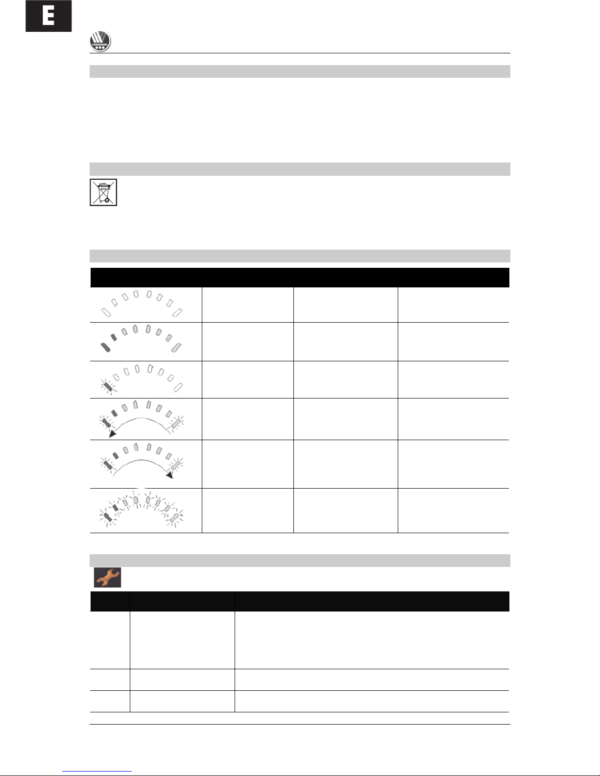
SHARK 2 DISPLAYS
Display Unit
Description
Meaning
Remarks
All LEDs dark.
System off.
All LEDs are lit.
System on.
LEDs show the charge
level.
Left red LED
flickering.
Low battery level.
Charge battery
immediately.
Progress indicator
from
“right to left” /
"green to red"
Shark system blocked.
To unlock, press the horn
button twice within 10
seconds after switching the
steering unit on.
Progress indicator from
“left to right” /
"red to green"
with subsequent
charge level display.
Shark is being
programmed, is connected
to the charger and/or is
busy charging.
The flickering LEDs
indicate the present
loading status.
All LEDs flickering
slowly.
After starting the system,
the joystick is not in the
neutral position.
Put the joystick in the
neutral position (let it go).
ERROR CODES
Symbol flickering fast at intervals. The number of flashes per interval provides the information below
(the following actions and checks should only be carried out by authorised individuals).
Number
Problem/Fault
Checks
0
There is no indication of
the charge level of the
batteries after the steering
unit is switched on.
1. Check whether the battery plug is inserted fully and correctly
connected to the socket of the steering unit.
2. Check whether the two batteries are connected correctly.
3. Check whether the batteries are charged.
4. Check whether the fuses of the steering unit and the batteries are
defective or have burnt out.
1
Operating error
1. Possible safety shut down or operating error (joystick)
2. Put the joystick in neutral position and restart the system.
2
Battery error
1. Check batteries and cabling; if necessary charge.
2. If necessary, replace batteries.
Progre
Progress
indicator

E
SQUOD_SU
06/2009
25
3
Left motor (or its
connection) is defective.
1. Check whether the plugs of both motors have been inserted properly.
2. Check the plug contacts of both motors for corrosion or damage.
3. Check both motors. Unplug the motors and measure the plug
connection with an Ohm meter. If you obtain readings of more than 1
Ohm or less than 100 milliOhms, the motor is defective.
4. Check the voltage difference between the motor and its housing.
Measure every contact between the motor and its housing by means
of an Ohm meter. If the resistance is less than 1 MegOhm, the motor
is defective.
5. Check the condition and function of the carbon rods of both motors.
N.B: If a fault is indicated in one motor, the other one could also be
defective.
4
Right motor (or its
connection) is defective
As described above.
(…)
Number
Problem/Fault
Checks
5
Left parking brake (or its
connection) is defective
1. Check whether the plugs of the motors have been inserted.
2. Check the plugs for corrosion or damage.
3. Check the parking brakes. Measure the resistance of the
connections by means of an Ohm meter. If the resistance is larger
than 100 Ohms or less than 20 Ohms, the parking brake is probably
defective.
6
Right parking brake (or its
connection) is defective
As described above.
7
Shark control is defective
1. Unplug both motors. Switch the steering off and then on again, while
leaving the joystick in the neutral position. If this flashing sequence
appears again, the steering is defective.
2. Unplug both motors. Again switch the steering off and on while
leaving the joystick in the neutral position. Then briefly push the
joystick in any arbitrary direction. If the steering relay then clicks
twice and a fault is indicated in the left motor, the steering is in order.
If any other fault is indicated and the steering relay does not click
twice, the steering is defective.
3. Check the motors as described above in 3. and 4.
N.B: If a fault is shown in one motor while driving, it could be
indicated as a steering fault.
8
Shark – PM defective
1. Check the cables and plugs for corrosion and damage.
2. Check the BUS connecting cable (resistance).
3. Replace the PM.
9
Shark communication
error
1. Check the cables and plugs for corrosion and damage.
2. Check the BUS connecting cable (resistance).
3. Replace the PM.
4. Replace the shark control.
10
Unknown error
1. Check the cables and plugs for corrosion and damage.
2. Check the BUS connecting cable (resistance).
3. See the manufacturer.
11
Incompatible steering unit
1. Incorrectly programmed and incompatible steering (depending on
system).
2. Check whether the programming of the PM and steering unit agree
with each other.

F
TABLE DES MATIÈRES
Chapitre Page
Table des matières ............................................................................................................................1
Avant-propos......................................................................................................................................2
Caractéristiques techniques...............................................................................................................2
Généralités.........................................................................................................................................3
Domaine d'utilisation ..........................................................................................................................3
Étendue de la fourniture.....................................................................................................................4
Explication des symboles...................................................................................................................4
Les organes de commande ...............................................................................................................4
Commande SHARK 2 ........................................................................................................................4
Réglage de l’unité de commande ......................................................................................................6
Dossier ...............................................................................................................................................6
Réglage de la profondeur d’assise ....................................................................................................7
Repose-jambes..................................................................................................................................7
Protection des genoux .......................................................................................................................8
Accoudoirs .........................................................................................................................................8
Sangle de poitrine ..............................................................................................................................9
Fonction debout/redressement ..........................................................................................................9
Chargeur ............................................................................................................................................10
Charger les batteries..........................................................................................................................11
Batteries .............................................................................................................................................12
Branchement des batteries ................................................................................................................12
Stockage des batteries ......................................................................................................................12
Raccordement du système ................................................................................................................13
Coupe-circuit thermique .....................................................................................................................13
Freins de stationnement ....................................................................................................................13
Pneus .................................................................................................................................................14
Remplacement des pneus .................................................................................................................14
Pousser le fauteuil roulant .................................................................................................................17
Transport du fauteuil roulant ..............................................................................................................17
Transport via des rampes ..................................................................................................................18
Accessoires........................................................................................................................................18
• Appuie-tête individuels (L55) .......................................................................................................18
• Ceinture de retenue de la personne (B58) ..................................................................................19
• Protection contre le basculement (B78) ......................................................................................19
• Coussins de maintien du tronc (L04) ...........................................................................................19
Pour votre sécurité .............................................................................................................................20
Contrôles réguliers .............................................................................................................................21
Inspection...........................................................................................................................................21
Outillage .............................................................................................................................................22
Entretien.............................................................................................................................................22
Stockage ............................................................................................................................................23
Désinfection .......................................................................................................................................23
Garantie .............................................................................................................................................25
Conformité .........................................................................................................................................25
Recyclage ..........................................................................................................................................25
Affichages SHARK 2 ..........................................................................................................................25
Codes d'erreur ...................................................................................................................................26

F
SQUOD_SU
06/2009
2
AVANT-PROPOS
Nous tenons tout d’abord à vous remercier pour la confiance que vous nous accordez en optant pour
l’un de nos fauteuils roulants.
Les fauteuils roulants électroniques Vermeiren sont le résultat de longues années d'études et
d'expériences. La durée de vie de votre véhicule dépend fortement du soin dont vous faites preuve
lors de son utilisation. Ce mode d’emploi doit vous aider à vous familiariser avec l’utilisation de votre
fauteuil roulant et vous donner quelques conseils pour maintenir celui-ci en état de fonctionnement et
lui assurer une longue durée de vie.
Ce mode d'emploi reflète l'état le plus récent de développement du produit. La société Vermeiren se
réserve toutefois le droit d’apporter des modifications sans obligation d’adapter ou de remplacer les
modèles livrés précédemment. N’oubliez pas que le respect de nos instructions vous permettra de
conserver votre fauteuil roulant en parfait état de conservation et de fonctionnement, même après des
années d’utilisation.
Si vous avez d’autres questions, veuillez vous adresser à votre revendeur.
CARACTÉRISTIQUES TECHNIQUES
(spécifiées pour le réglage standard (état à la livraison))
Les caractéristiques pour la longueur/hauteur totale changent si vous utilisez par exemple des appuie-tête supplémentaires.
Longueur (avec repose-pied relevé)
105 cm
Longueur (avec repose-pied abaissé)
123 cm
Hauteur (avec dossier)
99 cm / 109 cm
Hauteur (repose-pied jusqu'au bord
supérieur du siège)
55 cm / 57 cm / 59 cm / 61 cm / 63 cm
Hauteur (repose-pied jusqu'à l'appui de
genou)
47 cm / 49 cm / 51 cm / 53 cm / 55 cm
Réglage en profondeur de l'appui de
genou
15 – 21 cm (écart entre siège et appui de genou)
Hauteur (fonction debout maxi.)
143 – 153 cm / 148 – 158 cm / 153 – 163 cm / 158 – 168 cm
Largeur d’assise
44 cm
Largeur totale
65 cm
Profondeur d’assise (réglable)
40 cm / 45 cm / 50 cm / 55 cm
Hauteur d’assise
58 cm
Hauteur de dossier
51 cm / 61 cm
Hauteur d’accoudoir (siège-rembourrage)
20 cm / 22 cm / 24 cm / 26 cm / 28 cm / 30 cm
Hauteur d’accoudoir (rembourrage-sol)
71 cm / 73 cm / 75 cm / 77 cm / 79 cm / 81 cm
Moteur de réglage
Linak LA31, 24 Vcc, IP54
Moteurs d'entraînement
2 x 200 W Controls Dynamic Merits M3
Batteries
2 x AGM Gel 12 V / 70 Ah
Chargeur
Exendis Impulse S (8 A)
Commande
CD SHARK 2 / système de freinage électromagnétique
Poids (batteries comprises)
env. 121 kg
Température de fonctionnement
(électronique)
-20°Celsius à +40°Celsius
Coupe-circuit thermique
30 Amp.
Charge nominale (charge utile max.)
130 kg
Vitesse max.
6 km/h
Autonomie
env. 30 km
Pression de gonflage des pneus des
roues directrices*
max. 3,40 bars
Pression de gonflage des roues motrices*
max. 2,50 bars
Rayon de braquage
env. 140 cm

F
SQUOD_SU
06/2009
3
Pente max. franchissable
6° (10,5 %) en position assise
Hauteur max. des obstacles
60 mm (en position assise), Classe B
Sous réserve de modifications techniques. Tolérance dimensionnelle +/- 1,5 cm / kg
* Comme différentes possibilités de pneus existent, il y a lieu de respecter les pressions de gonflage indiquées.
GÉNÉRALITÉS
Le fauteuil roulant électronique SQUOD SU est équipé de deux moteurs d'une puissance de 200 watts
chacun. Il s’agit d’un véhicule mixte destiné à un usage tant à l’intérieur qu’à l’extérieur et avec
fonction debout/redressement utilisable sur sols plans en intérieur.
Si vous voulez utiliser votre fauteuil roulant électronique sur les trottoirs, vous devez veiller à respecter
les dispositions légales en vigueur. L’utilisation de ce produit sur route est tout à fait déconseillée. Le
modèle SQUOD SU étant une version limitée à une vitesse maximale de six kilomètres/heure, un
permis de conduire et une assurance ne sont pas obligatoires. Nous vous conseillons quand même de
souscrire une assurance libre en responsabilité civile. Nous vous invitons à prendre contact avec votre
assureur.
Après utilisation, mettez l'électronique du fauteuil hors tension. Pour charger les batteries, utilisez
exclusivement le chargeur de batterie livré avec le fauteuil.
Nous tenons à vous signaler que des pannes peuvent être provoquées par des sources
électromagnétiques (ex. : téléphone portable, etc.) et que l’électronique du fauteuil roulant peut ellemême causer des perturbations sur d’autres appareils électriques.
Même si votre revendeur vous a renseigné sur les organes de commande de votre fauteuil roulant
électronique et sur leur manipulation, vous devez lire attentivement les pages qui suivent.
DOMAINE D’UTILISATION
L’équipement et les accessoires permettent une utilisation en cas de handicap moteur dû à
• des paralysies
• la perte de membres (amputation des jambes)
• un défaut/une déformation des membres
• des contractures/lésions des articulations
• l’insuffisance cardiaque et circulatoire, les troubles de l’équilibre ou la cachexie ainsi que pour les
gériatriques.
En cas de prise en charge individuelle, il faut en outre tenir compte de
• taille et poids du corps
• état physique et psychique
• habitation et environnement
Votre fauteuil roulant doit être utilisé uniquement sur des sols permettant le contact des quatre roues.
Il convient de suivre une formation spécifique de conduite sur les surfaces irrégulières (pavés, etc.),
les déclivités et les virages (embardées latérales, etc.). Les déplacements sur des surfaces comme la
glace, l’herbe, le ballast, le feuillage, etc. sont particulièrement dangereux. Ce fauteuil ne peut être
utilisé comme siège dans un véhicule automobile.
La fonction debout/redressement ne doit être utilisée qu'en intérieur à des fins thérapeutiques et en
présence d'une deuxième personne. Les possibilités de conduite réduites ne doivent alors être
utilisées que pour mettre en place le produit. L'utilisation du mode de conduite en intérieur et en
extérieur n'est pas permise lorsque la fonction debout/redressement est sélectionnée. Il n'est pas
possible de passer des obstacles lorsque la fonction debout/redressement est sélectionnée.
L'utilisation du mode de conduite pendant la fonction debout/redressement est à vos risques et périls.
Une garantie ne peut être offerte que si le produit est utilisé dans les conditions prédéfinies et
aux fins prévues.
 Loading...