

Vermeiren Squod Instruction Manual
Instruction Manual
“SQUOD” Electric
Wheelchair
6 km/h
NV VERMEIREN BELGIE
Tel: 00 32 (0)3 620 20 20 • Fax: 00 32 (0)3 666 48 94
Vermeirenplein 1/15 • 2920 Kalmthout

SQUOD Instruction Manual
Last updated: Jul. 2005
Notice to the specialist dealer:
This Instruction Manual is part and parcel of the product and must accompany every wheelchair sold.
1. Edition 2005
All rights reserved, including translation.
No part of this manual may be reproduced in any form whatsoever (print, photocopy, microfilm or any other process) without
written permission of the publisher, or processed, duplicated, or distributed by using electronic systems.
© N.V. Vermeiren N.V., 2005
2

SQUOD Instruction Manual
Last updated: Jul. 2005
CONTENTS
Section Page
Contents ............................................................................................................................................ 3
Preface .............................................................................................................................................. 4
Technical details................................................................................................................................ 4
General notes .................................................................................................................................... 5
Applicability........................................................................................................................................ 5
Contents of the consignment ............................................................................................................ 5
Explanation of symbols...................................................................................................................... 6
Operating elements ........................................................................................................................... 6
Steering ............................................................................................................................................. 6
Adjustment of the steering unit .......................................................................................................... 7
Back .................................................................................................................................................. 8
Mechanical adjustment of the back.................................................................................................... 8
Mechanical adjustment of the seat..................................................................................................... 9
Leg supports...................................................................................................................................... 9
Armrests ............................................................................................................................................ 10
Batteries ............................................................................................................................................ 10
Charging the batteries ....................................................................................................................... 11
Connection of system ........................................................................................................................ 11
Connecting the batteries.................................................................................................................... 12
Battery storage .................................................................................................................................. 12
Thermal fuses.................................................................................................................................... 12
Parking brakes................................................................................................................................... 12
Tyres ................................................................................................................................................. 13
Tyre changing ................................................................................................................................... 14
Pushing the wheelchair...................................................................................................................... 15
Transporting the wheelchair............................................................................................................... 16
Using ramps ...................................................................................................................................... 16
Accessories ....................................................................................................................................... 17
• Individual headrest (L55)............................................................................................................. 17
• Leg supports ............................................................................................................................... 17
• Supporting system for persons (B58) .......................................................................................... 17
• Prevention of tipping over (B78).................................................................................................. 18
• Torso supports (L04)................................................................................................................... 18
For your safety................................................................................................................................... 19
Servicing............................................................................................................................................ 19
Inspection .......................................................................................................................................... 20
Care................................................................................................................................................... 20
• Covers......................................................................................................................................... 20
• Plastic parts................................................................................................................................. 20
• Outer coating............................................................................................................................... 20
• Electronics................................................................................................................................... 21
Storage.............................................................................................................................................. 21
Disinfection ........................................................................................................................................ 21
Guarantee.......................................................................................................................................... 24
Statement of conformity..................................................................................................................... 24
Shark 2 fault analysis......................................................................................................................... 24
Service plan....................................................................................................................................... 26
Addresses.......................................................................................................................................... 27
3

SQUOD Instruction Manual
Last updated: Jul. 2005
PREFACE
First of all we want to thank you for putting your trust in us by selecting one of our wheelchairs.
The electric wheelchairs supplied by Vermeiren are the result of reseach and experience over many
years. During the development simplicity of operation and servicing was especially emphasised.
But the expected working life of your vehicle depends essentially on your care and maintenance. This
instruction manual will help you to familiarise yourself with the operation of your wheelchair and advise
you about keeping your electric wheelchair in a good operating condition to ensure a long working life.
This instruction manual reflects the latest level of development of the product. However, our firm,
Vermeiren, reserves the right to introduce changes without any obligation to adapt or replace
previously delivered models.
Kindly keep in mind that your wheelchair will be in an excellent working condition and function
perfectly even after many years, if you follow our advice.
For any further questions, please consult your specialist dealer.
TECHNICAL DETAILS
Given in terms of the standard adjustments (condition of delivery)
The total length/height may be quite different when other leg and head supports are used.
Length (without leg supports) 82 cm
Length (with leg supports) 105 cm
Height (backrest included) 99 cm
Seat width 39 cm 44 cm 50 cm
Total width 60 cm 65 cm 71 cm
Seat depth 44 cm
Height of seat 53 cm
Height of backrest 51 cm
Height of armrests (seat cushion) 20 -25 cm
Height of armrests (floor cushion) 71 -76 cm
Motors 2 x 200 W Dynamic Controls M3
Batteries 2 x Gel 12V/73Ah
Battery charger Exendis Impulse
Steering CD SHARK 2 / Electromagnetic braking system
Weight (batteries included) Approx. 95 kg
Operating temperature of the electronics between -20° Celsius and +40° Celsius
Thermal fuses 30 AMP
Nominal load (max. load) 130 kg
Max. speed 6 km/h
Traveling range Approx. 30 km
Operating pressure, steering wheels* Max. 3.4 bar
Operating pressure, driving wheels*
Turning circle Approx. 140 cm
Max. climbing ability 6° (10.5 %) when sitting upright
Max. obstacle height 70 mm Class B (when sitting upright)
*Since different tyres may be used, please note the correct operating pressure of the specific tyres you use.
We reserve the right to introduce technical changes. Measurement tolerance +/- 15 mm / kg
Max. 2.5 bar
0
4

SQUOD Instruction Manual
Last updated: Jul. 2005
GENERAL NOTES
The SQUOD electric wheelchair is equipped with two motors of 200 Watt each. It has been designed
for mixed usage, both inside and outside.
When using your electric wheelchair on streets or footpaths, you must obey the existing legal
prescriptions.
Since the SQUOD has a top speed of six km/h, you do not require a driving licence and neither is
vehicle insurance necessary. However, we recommend that you take out voluntary third-party
insurance. Kindly contact your insurer.
The electronics must be switched off immediately after use of the wheelchair. Use only the supplied
battery charger and no other charging equipment.
We wish to point out that electromagnetic sources (e.g. "Handy", etc.) can cause interference and that
the electronics of the wheelchair can also affect other electric appliances.
Even if you have been instructed by your specialist dealer about the operational elements of your
electric wheelchair and their use, we recommend that you read the following pages carefully.
APPLICABILITY
The many types of equipment and accessories as well as the modular construction allow full use by
persons disabled by
• Paralysis
• Loss of limbs (leg amputation)
• Limb defects / Deformation
• Stiff or damaged joints
• Diseases like heart problems, poor circulation, disturbance of balance or "Kachexie" as well as for
aged persons.
When providing for individual requirements
• body size and weight
• physical and psychological condition
• residential circumstances and
• the environment
should also be taken into consideration.
Guarantees can only be honored when the product is used under the prescribed conditions
and for the intended purposes.
CONTENTS OF THE CONSIGNMENT
• The frame structure including the motors, the seat, and the back unit
• Footrests (standard: B06; removable, can be turned aside)
• 2 x Batteries including the battery boxes
• Back strap
• Tip protector
• Battery charger
• Steering electronics
• Tools (Allen keys)
• Instruction Manual
5
SQUOD Instruction Manual
Last updated: Jul. 2005
EXPLANATION OF THE SYMBOLS
Observe the safety instructions!
Read the instruction manual before use!
Position: Parking brakes activated (electronic driving possible)
Position: Parking brakes deactivated (free running and pushing possible, no electronic driving)
During free running, be careful with slopes and inclinations
Separate recovery and recycling of electric and electronic devices
THE OPERATING ELEMENTS
The electric wheelchair is delivered fully assembled. Only the footrests have to be fixed (see the
relevant description). Your specialist dealer delivers the wheelchair fully assembled and informs you
about the various operating elements and their use. For your own safety we once more provide a
detailed explanation of the various structural parts.
STEERING
The steering and control unit built into your electric wheelchair enables you to control all the driving,
steering and braking processes of the vehicle. The electrical installation as well as the electronics of
the wheelchair are constantly monitored internally. Any fault in the electronics is indicated on the
steering unit and, if necessary, the wheelchair is switched off for reasons of safety (see the chapter on
fault analysis). Consult your specialist dealer when this happens.
2
8
5
1
9
3
4
6 7
10
11
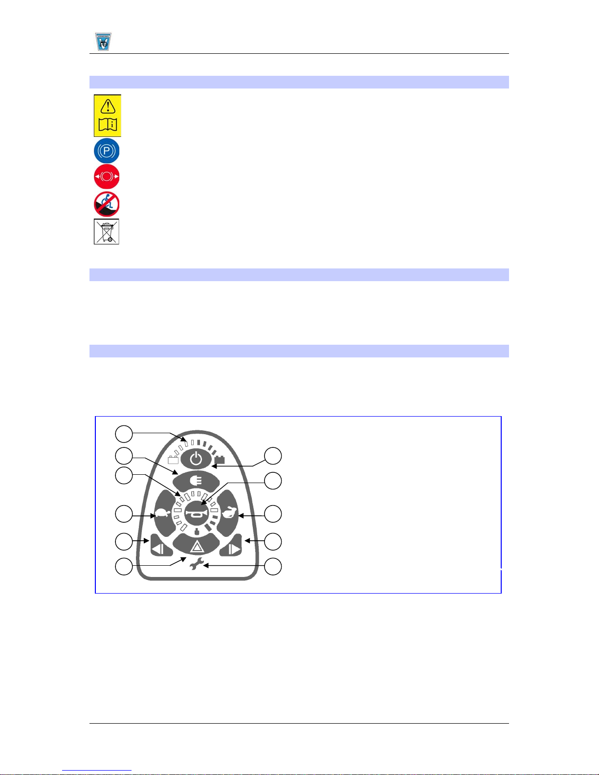
Press the "ON/OFF" button (1). The charge indicator (2), which also indicate the level of charge of the
batteries, lights up for a moment. If all lamps light up, the batteries are charged sufficiently. If some
lamps do not light up, you must adjust your driving activities according to the low capacity of the
batteries. If the lamps of the battery charger do not light up, check the plug connections of the
electronic system.
Now select the desired driving program by pressing on button “Tortoise” (3) or “Hare” (4).
The selected speed can be set on the 5-level speed indicator (5). If you have special requirements,
you can ask your specialist dealer to enter an individual driving program.
1 = On/Off button
2 = Battery charge indicator
3 = Lower speed (“Tortoise” symbol)
4 = Increase speed (“Hare” symbol)
5 = Speed indicator
6 = Left indicator light
7 = Right indicator light
8 = Lighting
9 = Horn
10 = Emergency flashers
11 = Service indicator (fault analysis)
6

SQUOD Instruction Manual
Last updated: Jul. 2005
To set the wheelchair in motion, push the joystick slowly forwards. The speed will increase when you
push the joystick further forwards. If you want to turn left or right, simply push the joystick in the
desired direction. For reversing, pull the joystick backwards from the central position.
L Note that when pressing the "ON/OFF" button, the joystick stays in the central position for at
least two seconds. It is programmed this way for technical reasons of safety to prevent
pushing the joystick at the same time as switching the wheelchair on. If both processes are
activated at the same time, the steering unit locks itself and can only become operational
again after being switched off completely.
Press the button “Left indicator” (6) or “Right indicator” to signal a change in your driving direction. The
driving lights are switched on or off by pressing the “Light” (8) button. You can sound an acoustic
warning signal with the “Horn” (9) button. The emergency flashers used in critical situations can be
switched on or off by pressing the “Emergency flashers” (10) button.
For braking while driving, simply push the joystick to its central position. Move the joystick slowly for
gradual braking. Simply release the lever for a quick stop; the wheelchair will then stop as quickly as
possible.
L Make sure that all plugs (battery charger and programming unit) are removed before setting
the wheelchair in motion.
L Make sure that the steering lever is in the neutral (central) position when pressing the on/off
button, otherwise the electronics will be blocked. This barrier can be lifted by switching the
steering unit off and then on again.
L Always adapt your traveling speed to the prevailing environmental conditions.
ADJUSTMENT OF THE STEERING UNIT
The horizontal position of the steering unit can be changed by loosening screw (1). The unit can then
be adjusted as desired, or removed. Screw (1) must then be retightened properly. If screw (1) is pulled
aside, the steering unit can be turned aside.
REMARK: Depending on the features of your wheelchair, the screw (1) could also be located under
the driving rod (2).
2
1
7

SQUOD Instruction Manual
Last updated: Jul. 2005
BACK
For transportation purposes the back section is removable.
Loosen the levers (1) to lift the entire back section and its
tubing out. Now it is easy to push the wheelchair into a car by
2
1
means of a ramp, for example. For driving, insert the back
tubes evenly and fully on both sides into the frame
receptacles. Levers (1) must then be retightened properly.
Before use, check that the back is fixed properly to the back
tubing. If it is loose, retighten the safety screws (2) which fix
the back to the back tubing.
Check that the back tubing is not jammed, otherwise the back might be tensioned and/or it
L
might not be inserted correctly. Deformations which could endanger the safety of the
wheelchair and its user, might be caused.
L Before using the wheelchair, check that the fixing screws (1) are tightened properly, otherwise
the back might come loose, damage the chair and hurt the user.
L Make sure that no extra loads hang from the back (e.g. rucksack, etc.) which might increase
the danger of tipping over backwards.
If the functioning of the back or some of its components has deteriorated because of wear and tear or
other causes, kindly consult your specialist dealer. He shall gladly assist you further.
MECHANICAL ADJUSTMENT OF THE BACK
By loosening the screw handles fitted on the side of the back tube (1), you can tilt the back backwards
for a max. of 30°. Loosen the screw handles (1) on both sides of the backframe till you can move it
freely. Set the back to the desired position and securely retighten the screw handles (1) on both sides
of the backframe. Check whether the backframe is tight.
1
The back setting should not be changed with the user sitting in the wheelchair.
L
L Before using the wheelchair, check that the safety screws (1) on both sides of the backframe
have been tightened properly, otherwise the back might come loose, damage the chair and
hurt the user.
8

SQUOD Instruction Manual
Last updated: Jul. 2005
MECHANICAL ADJU S T MENT OF THE SEAT
It is possible to change your sitting position by setting the cushioned seat to a different angle.
To change the angle of the seat (max. 9°), go through the following sequence:
A. Lift the seat (1) completely from the seat frame (3).
B. Reposition the fixing screws of the front seat suspension (2) and securely tighten again (this
C. Put the seat back on the seat frame in such a way that the seat suspension is located on the frame
1 2 1 2
3 3
adjustment can only be done with a suitable slotted screwdriver).
between the banking pins. By gently pressing on the seat, the seat suspension will lock onto the
seat frame.
L Let an expert perform these activities.
L See to it that the seat suspension is located between the banking pins on all sides.
LEG SUPPORTS
To mount the leg supports, place them sideways with
the bolts (1) in the sockets of the frame tube (2). Now
turn the leg supports slowly inwards until the locking
7
5
8
1
3
2
block (3) slides over the suspension block (4). The
release lever (5) engages automatically when the end
position is reached.
To unbolt the leg supports, press the release lever (5)
gently downwards and turn the leg supports outwards
or inwards.
L Before use, make sure that the leg supports
are securely locked in place.
6
Adjusting the footplates
The footplates (6) can be set at different heights. Loosen the screw on the footplate. Now move the
boards backwards or forwards by about 3 cm. It should be secured again with the fixing screws.
Depending on the steering wheel combination and the adjustment of the steering wheel adapter, the
footplate cannot be pushed backwards, since it would obstruct the steering wheel.
Distance below the thigh
To adjust the length of the leg supports, remove screw (7) which holds the leg support, pull the inner
tube (8) to the desired position, and secure again by means of screw (7). Before use, make sure that
all screws have been tightened properly.
Kindly consult your specialist dealer about the correct adjustment of your leg supports. He would
gladly aid you and advise you about other available leg support systems.
Before use, make sure that the leg supports are securely locked in place.
4
9
 Loading...