

Vermeiren INOVYS Instruction Manual
VERMEIREN
INSTRUCTION MANUAL
MODE D’EMPLOI
GEBRUIKSAANWIJZING
GEBRAUCHSANWEISUNG
ISTRUZIONI PER L'USO
MANUAL DE INSTRUCCIONES
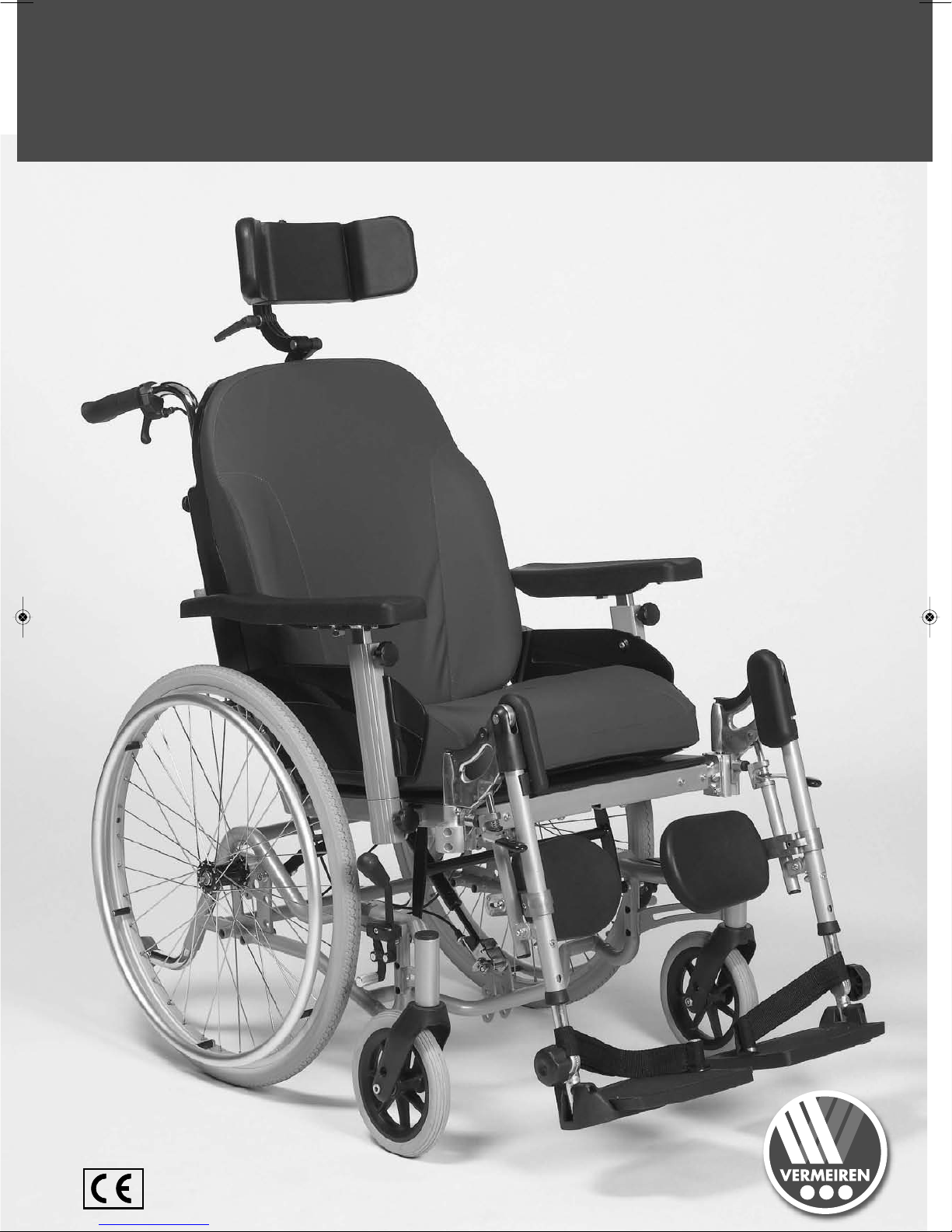
INOVYS

708 D
10/2007
22

GB
F
NL
D
I
....... p02 - p22
....... p23 - p42
....... p43 - p62
....... p63 - p82
....... p83 - p102
....... p103 - p122
E

708 D
10/2007
22

INOVYS
12/2008
3
CONTENTS
Section Page
Contents.............................................................................................................................................3
Preface...............................................................................................................................................4
Usage.................................................................................................................................................4
Components of wheelchair (scope of delivery)..................................................................................5
Specifications.....................................................................................................................................5
Assembly ...........................................................................................................................................6
• Frame....................................................................................................................................6
• Armrests................................................................................................................................6
• Leg supports .........................................................................................................................6
• Seat cushion .........................................................................................................................7
• Head rest ..............................................................................................................................7
• Pushing handles ...................................................................................................................7
• Anti-tipping............................................................................................................................7
Adjusting armrests .............................................................................................................................8
Adjusting leg supports................................................................................................ ........................8
Adjusting head rest ............................................................................................................................10
Using the springs (seat inclination / angle of backrest)......................................................................11
Adjusting the seat height....................................................................................................................11
Adjusting the seat depth ....................................................................................................................12
Parking brakes...................................................................................................................................13
Accessories........................................................................................................................................13
• Side supports (L04)...............................................................................................................13
• Personal safety belt (B58).....................................................................................................14
• Wooden table (B12) ................................................................ ..............................................14
• Horizontal wedge (B22) ........................................................................................................14
Transporting the wheelchair............................................................................................................... 14
Using ramps................................................................................................................................ .......15
Tyre changing ................................ ...................................................................................................15
For your safety...................................................................................................................................17
Regular checks ..................................................................................................................................17
Inspection................................................................................................................................ ...........18
Care ...................................................................................................................................................18
Disinfection ........................................................................................................................................19
Tools .................................................................................................................................................. 22
Guarantee ..........................................................................................................................................22
Conformity..........................................................................................................................................22
Disposal .............................................................................................................................................22
Service................................................................................................................................ ...............123
Notice to the dealer:
This instruction manual is part and parcel of the product and it should accompany each product delivered.
Last updated: 02/2008
All rights reserved, including translation.
No part of this manual may be reproduced in any form whatsoever (print, photocopy, microfilm or any other process) without written permission of
the publisher, or processed, duplicated, or distributed by using electronic systems.
N.V. VERMEIREN & Co., 2007
GB

INOVYS
12/2008
4
PREFACE
First of all we want to thank you for putting your trust in us by selecting one of our wheelchairs.
Vermeiren wheelchairs are the result of research and experience acquired over many years. During
development we placed great emphasis on simplicity of operation and maintenance.
The working life of the wheelchair depends to a large extent on the care with which you use it. This
instruction manual will help you to get acquainted with the operating of your wheelchair. It also advises
you on how to keep your wheelchair in a good operating condition to ensure a long working life.
In principle, the wheelchair is delivered to the user completely assembled. Adjustments which require
a tool, additional assembly but also attaching replacement parts as well as repairs are to be conducted
on principle by authorised individuals.
Please keep in mind that compliance with our instructions will contribute to your wheelchair remaining
in top condition and fully operational even after many years of use.
This manual reflects the latest state of development of the product. However, Vermeiren reserves the
right to introduce changes without any obligation to adapt or replace previously delivered models.
If you have any further questions, kindly consult your specialist dealer.
APPLICABILITY
With the INOVYS model, you have acquired a multi-functional wheelchair that was developed entirely
for your comfort. The INOVYS model is intended exclusively for individuals with limited mobility who
would like to use the wheelchair themselves or with the aid of an attendant indoors and to a limited
extent outdoors and require a special resting position. Ride only over flat surfaces with firm ground. It
should not be used to drive on ground such as gravel, mud, cobble stones, grassy surfaces, or other
ground that is not firm or level.
Take note of warnings, danger is possible (risk of tipping, crushing possible, etc.)
Please read the instruction manual carefully to familiarize yourself with your wheelchair.
The many variations in equipment and accessories as well as the modular structure allow for use with
movement limitations based on:
paralysis
loss of limbs (leg amputation)
weak/malformed limbs
spasms/injuries of the joints
diseases like heart problems, poor circulation, disturbance of balance, cachexia and old-age
illnesses
For individual adaptation the following elements must be take into account:
body size and weight (max. load 297.62 lb)
physical and psychological condition
residence and
environment
Any guarantees will only apply if the product is used under the prescribed conditions and for
the specific purposes intended herein.
GB
INOVYS
12/2008
5
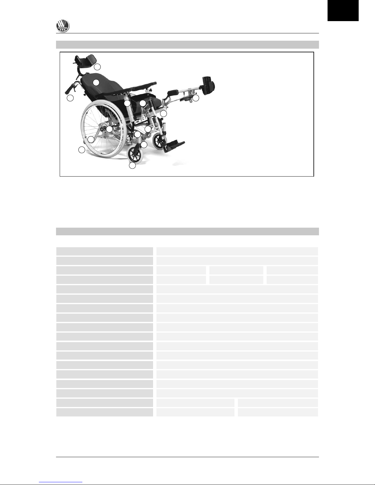
COMPONENTS OF THE WHEELCHAIR
NOTE TO DEALER:
When you receive the goods, please check that the product supplied is complete and fully functional.
Warranty claims are only valid if the manufacturer (supplier) is notified in writing within a period of two
weeks. In the case of any defect that is not immediately evident, warranty claims are only valid if the
manufacturer (supplier) is notified in writing within two weeks after it is detected. We shall remedy
defects in the manner of our choosing - either by carrying out a repair or by providing a replacement.
SPECIFICATIONS
(given in fully assembled condition and as standard equipment)
Total length
43.31 in.
Total length (without leg supports)
31.50 in.
Total width
23.62 in.
25.59 in.
27.56 in.
Seat width
15.75 in.
17.72 in.
19.69 in.
Height of backrest
19.69 in.
Total height
40.55 in.
Adjusting seat height
17.72 in – 20.47 in
Seat cushion
3.15 in.
Seat depth
16.54 in – 18.50 in
Height of armrests
7.48 in – 11.02 in
Total weight
Approx. 81.57 lb
Seat angle
Approx. 21°
Angle of backrest
Approx. 35°
Max. nominal load
Nominal load 297.62 lb
Tyre pressure front wheels *
Max. 2.5 bar
Tyre pressure rear wheels *
Max. 3.5 bar
Colour of frame
C55
Cover
Soft grey
We reserve the right to introduce technical changes. Tolerances +/- 0.59 in/kg, 1.5°
* Tyre pressure given is for standard tyres. If using tyres made by another manufacturer, please refer to the tyre cover for
details of the pressure.
SCOPE OF DELIVERY
(Standard equipment)
1. Back wheels (24 x 1⅜)
2. Front wheels (8 x 1¾ ) or (8 x 1¼)
3. Basic frame
4. Seat frame
5. Back rest
6. Armrests
7. Seat cushion
8. Pushing handles
9. Parking brakes
10. Head rest
11. Leg supports
12. Front wheel bracket
13. Floating axles
14. Anti-tipping device
1
2 3 4 5 6 7 8 9 10
11
12
13
14
GB

INOVYS
12/2008
6
ASSEMBLY OF THE WHEELCHAIR
Note the following before assembling the wheelchair:
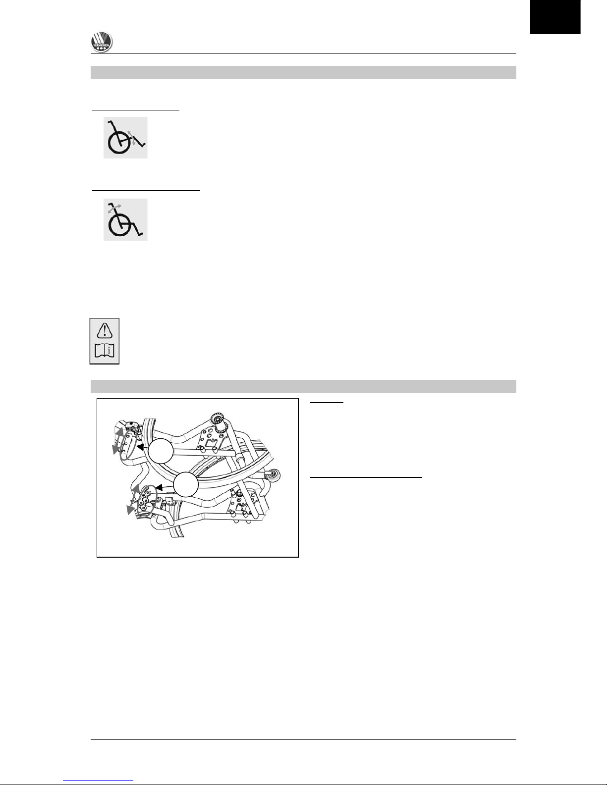
FRAME
After you have taken the wheelchair out of the original
packaging, push the backrest to the back into the 90°
position. Guide the safety pins (A) into the appropriate
socket to peg the spring (B), which is located at the
back under the seat.
L Make sure that the ring of the pin is closed.
L Make sure that no cables are squashed.
ARMRESTS
Put the armrests to the left and the right into the
brackets provided for this purpose. Pull out the screw
(1). Guide the armrest from above into the bracket (2)
provided. Let go of the screw (1) and this will stop the
armrest. Turn the screw clockwise until it is finger-tight
(3) so that the armrest is also secured. To loosen and
remove the armrest, proceed in the reverse order.
L Make certain before use that the armrests are
firmly fixed.
LEG SUPPORTS
Grasp the leg support on the upper handle by guiding
your finger through the handle. From above press with
your thumb on the hatched surface of the leg support
handle (1) and the lock of the leg support is loosened.
Pull the leg support vertically up to remove the leg
support (2).
If you want to swivel the leg supports to the side, pull
the leg supports up by about 0.98 inch and set the
swivelling block to the side on the receiver block of the
leg support (3).
To insert the leg support, grip the leg support on the
upper handle, press on the hatched surface of the leg
support handle (1) and guide the narrow axle into the
leg support receiver. The leg support block and the
leg support receiver have to lie flush in each other,
only then is the floating axle locked and the leg
support secured.
L Make sure that the axle is locked before using
the leg support.
A
B
1
2 3 1
2
3
GB

INOVYS
12/2008
7
SEAT CUSHION
Lay the seat cushion on top of the premounted seat. It can then be fastened to the loop straps of the
seat with the hook straps on the underside of the cushion.
HEADREST
Attach the headrest to the place on the top of the
backrest provided for this purpose (1).
The height can be set with the help of the threaded
screw (2).
L Tighten the threaded screw (2) well after making
the adjustment.
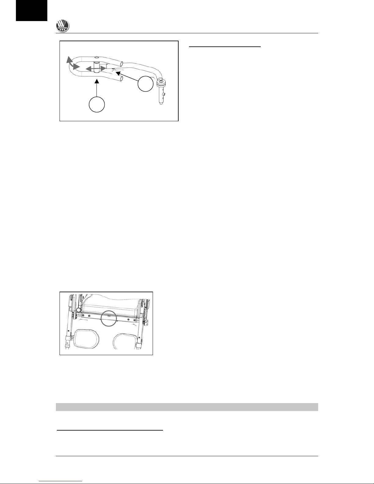
PUSHING HANDLES
The pushing handles can be adjusted in height
depending on the size of the attendant.
Loosen the knurled screws (1) and pull the pushing
handles into the position desired.
Indentions have been placed into the tubing of the
pushing handles, which is where the knurled screws
have to grab to tighten. As soon as the desired height
is achieved, tighten the knurled screws (1) firmly.
L Tighten the knurled screws (1) well after making the adjustment.
L For a maximum height adjustment, use only the last indentation of the pushing handle tube
since otherwise the stability of the pushing handle is endangered.
ANTI-TIPPING
HEIGHT ADJUSTING
• Press in the spring button (1) and press the tilting
bracket into the frame tube or out of the frame
tube until the desired position is reached and the
spring button can once again click into position (3
positions).
• To deactivate the anti-tipping, the tilting bracket
can also be turned by 180° and the spring button
then clicks on the side opposite of the frame tube.
L Make sure that when using the anti-tipping it
is so adjusted that the wheelchair cannot flip
over.
L Make sure that the anti-tipping is set in the same position on both sides.
L Do not use the anti-tipping as a tipping lever. For this, use the crossbars (A) by grabbing the
handles of the back and press with your foot on one of the two crossbars (A) until the chair
slightly tilts to the back.
1
2
1 1 2
1
A
GB

INOVYS
12/2008
8
ADJUSTING THE ARMRESTS
HEIGHT ADJUSTING
• Pull out the safety screw (1)
• Pull the armrest into the required position (2)
• Let go of the safety screw until it clicks into the
desired position (1)
• Turn the safety screw securely for additional
tightening (3)
DEPTH ADJUSTING OF ARM CUSHION
• Loosen the fixing screw beneath the arm cushion
(4)
• Push the arm cushion into the desired position (5)
• Then retighten the fixing screw (4)
WIDTH ADJUSTING OF THE ARMRESTS
• Loosen the screws (A) of the armrest sockets
beneath the seat.
• Pull the armrest socket into the desired position
(max. of 1.97 in outwards).
• Tighten the screws (A) finger-tight again.
L Pull out the armrest socket only to the extent
that both screws on one side still secure the
armrest socket.
ADJUSTING THE LEG SUPPORTS
The angle of inclination can be easily adjusted by
lifting the leg support with one hand. When letting go,
it will automatically lock in the desired angle (up to
113°). To lower the leg support, pull the handle (A) up
until the desired angle is reached.
L To adjust the angle of the leg supports, only
touch them at the level of the footplates –
otherwise fingers may be squashed !
ADJUSTING CALF CUSHIONS
Adjusting the height:
Loosen the screw of the clip block (B), bring it to the
desired height and retighten the screw firmly.
Adjusting the depth:
Loosen the screw (C), bring the calf cushion on the
rail into the desired depth, and then tighten the screw
again firmly.
1 2 3 4 5
A
A
A
B
C
GB

INOVYS
12/2008
9
LOCKING LEG INTO HIGH POSITION
To lock the leg support into the desired position,
tighten the screw (D) finger-tight. Before the leg
support can be let down, the screw (D) must first be
loosened. Only then can the leg support be adjusted
in its angle with the trigger lever (A).
ADJUSTING THE BASIC POSITION
Due to the adjustability of the wheelchair, it could be
possible that depending on the selection of wheel
size, seat height and seat depth, a collision may occur
between the footplates and the steering wheels. This
collision can be avoided with the adjusting screw (E)
since with this adjusting screw (E) you can determine
to what extent the leg support can be put into the
lowest position.
ADJUSTING THE LENGTH
In order to adjust the leg support in length, loosen the
screw (F) and put the footplate’s plug-in tube into the
desired position and reinsert the screw (F). Several
holes are available to you for securing.
ADJUSTING THE FOOT ANGLE
Loosen the black knurled screw (G), put the footplate
into the desired angle and retighten the screw fingertight.
ADJUSTING THE DEPTH OF THE FOOTPLATES
Loosen the two screws (H) on the footplate, select the
desired depth (three positions are possible), and
retighten the screws firmly.
G F
H
D E
A
GB

INOVYS
12/2008
10
ADJUSTING THE WIDTH
Loosen the screw (A for right / B for left) and the leg
support socket can be moved further out by about
2.36 in. After selecting the desired position, secure the
screw (A and/or B) again firmly.
L Pull out the leg support socket only to the
extent that both screws on one side still
secure the leg support socket.
L Before using the leg supports, make sure that all screws and adjusting units have been
tightened properly.
Please keep in mind that the selection of adjusting functions and settings have an effect on the user.
Should you be uncertain whether the set functions and adjustments are suited for the user, please get
in touch with your specialist dealer.
ADJUSTING THE HEADREST
ADJUSTING THE HEIGHT/DEPTH
Loosen the levers (1) and put the headrest into the position
desired. Levers (1) must then be retightened properly.
ROTATION OF THE CUSHION FRAME
The cushion frame can be turned up to 360° to adjust to a
slanted head position. Loosen the lever screws (2) and turn
the cushion frame into the position desired. The lever must
then be retightened properly.
ADAPTING THE SIDE OF THE CUSHION FRAME
The cushion frame can be pushed sideways. Loosen the
screw (3) and push the cushion frame into the position
desired. The screw must then be retightened properly.
To support the head to the side, the headrest can be adapted to the head by slightly pressing the side
panels forwards. In this way, tipping of the head to the side can be avoided.
L Make sure that all adjusting screws are properly tightened.
L Make sure that the settings of the headrest correspond to the posture of the patient, and no
pressure or resistance is exercised.
L Settings for the headrest must be done by authorized people only.
A
B
1 1 1 2 3
GB
INOVYS
12/2008
11
USING THE SPRINGS (SEAT INCLINATION/ ANGLE OF BACKREST)
The seat and the backrest can only be adjusted simultaneously or independently from one another in
their angle by an attendant.
SEAT INCLINATION
Use the lever to the left (see label) that is located below the pushing handle for the
attendant until the desired position is achieved, and then let it go to block the spring.
The adjustable angle for the seat: 0° to + 21°.
CAUTION: When equipped with drum brakes, this lever is located above the
pushing handle and is triggered with the thumb.
BACKREST ADJUSTING
Use the lever to the right (see label) that is located below the pushing handle for the
attendant until the desired position is achieved, and then let it go to block the spring.
The adjustable angle for the backrest: 0° to +35°.
CAUTION: When equipped with drum brakes, this lever is located above the
pushing handle and is triggered with the thumb.
L The use of the adjusting functions is only possible by an attendant.
L Make sure that the wheelchair’s brakes are always activated before using the adjusting
functions so that the wheelchair does not unintentionally roll away while the adjustments are
being made (see section “Parking brakes”).
Make sure that when using these adjusting functions the wheelchair’s tipping stability is
changed.
Adapt the tip protector to the respective conditions (see section “Assembly of the wheelchair”,
tip protector).
ADJUSTMENT OF THE SEAT HEIGHT
FRAME
The basic frame and the seat frame are screwed
together beneath the parking brake (A). In the
basic frame four different sockets are provided
for these screws which determine the
wheelchair’s seat height.
GAS PRESSURE SPRING
In addition to adjusting the frame, the gas
pressure spring for the seat inclination can be
fixed at three different attaching heights (B). So
that the angle of inclination can be kept for the
seat inclination, the assembly height of the gas
pressure spring (B) must correspond to the
assembly height of the frame fixture (A).
The angle of the seat inclination can be changed by different assembly heights of frame (A) and gas
pressure spring (B), so that even the seat can be tipped forward up to 7°.
L Rebuilding the seat height is only to be done by authorised individuals who can judge the
technical and functional safety.
L Make sure that all screws are secure and properly tightened.
L Self-locking nuts are only to be used once or are to be secured with an additional screw
locking device.
L When rebuilding the height of the seat, the brake settings are to be checked and if necessary
adjusted.
L The manufacturer assumes no liability for any damages or injuries resulting from improper
assembly of the seat height.
A
B
GB

INOVYS
12/2008
12
DRIVING WHEELS
Four possible wheel sockets are provided in a swage
block of the frame for the use of driving wheels
(22”/24”) (A). Depending on which suspensions are
used to attach the driving wheels, the wheel position
and the seat height can be changed. The wheel
sockets attached in the delivery condition can be
attached in all sockets (boreholing)
The wheel sockets in the frame tubing (B) serve only
to attach 16” wheels (transit version).
STEERING WHEELS
In the standard model, the INOVYS is delivered with
two 8” steering wheels (200 mm x 50 mm or 200 mm
x 35 mm).
L Assembly work is to be conducted only by authorised individuals.
L Before using the wheelchair, all screws are to be checked for tightness.
L The manufacturer is not liable for damages due to assembly measures in the combination of
frame, gas pressure spring and wheels, which endanger the safety of the user or full
functionality of the wheelchair.
ADJUSTING THE SEAT DEPTH
Loosen the screw beneath the front seat
frame (A). Pull the front of the seat frame into
the desired position and then tighten the
screw firmly again.
L Rebuilding the seat depth is to be
done by authorised individuals who
can judge the technical and functional
safety.
L Make sure that all screws are secure
and properly tightened.
L Note that when rebuilding the seat depth in the back frame area, the displacement of the
spring for adjusting the back is changed and that a gap can occur between the back and seat
cushions.
L The manufacturer assumes no liability for any damages or injuries resulting from improper
rebuilding of the seat depth.
A A B
GB

INOVYS
12/2008
13
PARKING BRAKE
The brake serves only as a parking brake and not to brake the wheelchair when it is moving.
BRAKES
To activate the brake, press the lever
forwards. To release the brake, press the
lever backwards.
BRAKE SETTING
Loosen the two screws of the track
suspension with which the brake unit is
connected to the frame without removing it
from the frame (1). Push the brake unit into
the desired position (2) and then tighten both
screws firmly.
L Brake settings are to be conducted
only by authorised individuals.
ACCESSORIES
As additional equipment for your multi-function wheelchair use only the original accessories from the
wheelchair manufacturer and observe the following tips:
• SIDE SUPPORTS (L04)
The side supports can be lowered and are adjustable
in height, width and length. The sockets are behind
the back beneath the pushing handles.
ATTACHING
Place the support into the support socket behind the
back in such a way that the head of the adjusting
screw (A) fits into the slot of the support socket.
LOWERING
Lift the support until the head of the adjusting screw
(A) has left the slot of the support socket. Turn the
support inwards or outwards, whereby the head of the
adjusting screw (A) can be guided on the edge of the
support socket.
HEIGHT ADJUSTING
The side height of the supports is set by changing
the position of the adjusting screw (A) on the
vertical tube of the side support.
WIDTH ADJUSTING
The width is set by loosening the screw (B) and
then the toothed wheel so released can be guided
into the desired position.
A
B
2
1
A
GB
INOVYS
12/2008
14
ADJUSTING THE LENGTH
The length of the side supports is set by loosening
the screw (C) on the horizontal tube of the side
support (3 positions). Afterwards, the screw is
tightened again.
The support independently adapts its position to
the side of the body via the axle (D).
L Make sure after making the adaptation that only padded parts are touching the body as
otherwise pressure points can occur.
L Please check all screws are securely fastened before using.
l Assembly and adjustment measures should only be conducted by authorised individuals.
L The manufacturer assumes no liability for any damages resulting from the improper adjusting
of the side supports.
• PERSONAL SAFETY BELT (B58)
For your safety we offer a personal safety belt. Holes are provided to attach it in the angle of the
seat/back frame. If you prefer other types of fixing, contact your specialist dealer. He will mention
further possibilities.
l Let your specialist dealer fit these to ensure proper mounting.
Please consult your specialist dealer if you require other safety belt systems. He shall gladly assist
you further.
• TREATMENT TABLE POLYCARBONATE (B112)
We offer a wooden treatment table made. The table is removable and be flipped to the side.
l Make sure when assembling that the cover and the cushion are not damaged.
• HORIZONTAL WEDGE (B22)
Many illnesses and disabilities require that your thighs have to
be pushed apart by means of a wedge. For this purpose we
offer a cushioned egg-shaped buffer the size of a fist which
can be put into the required position by means of a connecting
rod mounted beneath the seat in a gap of the frame.
l Only your specialist dealer may fit and position this wedge.
l We do not accept any liability for damage and/or injuries caused by the wedge being fitted by
unauthorised persons.
TRANSPORTING THE WHEELCHAIR
Note the following before transporting the wheelchair:
TRANSPORTING WITHOUT A PATIENT
Since the multi-function wheelchair cannot be folded, at least two persons are required for its
transportation.
C
D
GB

INOVYS
12/2008
15
By operating the relevant levers, set the seat in a horizontal position and the backrest vertically. Then
remove the leg supports. The head-resting systems can be removed completely by loosening the
fixing screws. Please remove the leg supports and the armrests (look in the respective sections of this
manual). The wheelchair can now be lifted and transported.
l Never pick the wheelchair up by grasping the wheels, but only by taking hold of solid frame
parts (undercarriage) in the front and at the back.
l When assembling, make sure that all screws are retightened properly.
TRANSPORTING WITH A PATIENT
If you want to be taken upstairs or downstairs, remove the anti-tipping wheels which would normally
act for your protection, but would now prevent the driving wheels from rolling on the stairs.
l Lifting the wheelchair while the patient is seated in the wheelchair is forbidden !
l Transporting a patient over steps/stairs is to be done with at least two attendants.
Next make sure that the pushing handles are sufficiently tight and remove the leg supports. Slightly tilt
the wheelchair backwards. The wheelchair can then be pushed forwards step by step using the driving
wheels. A second person is required to secure the wheelchair in front by taking hold of the front of the
frame after removing the leg supports. He then walks backwards.
l Note that, when the footrests have been removed, the legs of the patient are not secured;
danger of injury !!
l When being transported, you should be protected by suitable safety belt systems (information
obtainable from your specialist dealer).
l When being transported, sit quietly in your wheelchair and avoid jerky movements.
l If you cannot sit quietly when being transported because of illness or disability (e.g. slightly
spastic, etc.), then at least two persons are required to secure the wheelchair on both sides by
taking hold of fixed parts of the frame.
l If the anti-tipping device is removed, you are not protected against tipping over backwards.
l When being transported, make sure that your arms and legs do not protrude outside the
wheelchair.
l When being transported, no persons or objects should be below the wheelchair, to prevent
personal injury or damage to the wheelchair.
l For transporting in cars, we recommend that you use the existing seats with their seatbelt
systems. The use of the multi-functional wheelchair as a seat in a motorised vehicle is not
allowed.
USING RAMPS
If you are considering the installation of ramps to overcome obstacles, kindly note the following:
Because of the large weight of the wheelchair we advise against using your own power for driving on a
ramp, since it might not be possible for you to prevent the wheelchair from rolling backwards.
Never go up or down ramps without the aid of a helper.
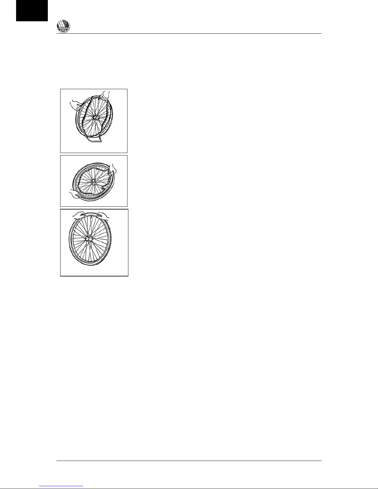
TYRE CHANGING
If you wish to change the tyres or tubes, please note the following tips:
After letting all the air out of the tube, insert a tyre lever between the tyre and the rim for the purpose
of removing the tyre. Then slowly and gently push the tyre lever downwards. This will pull the tyre over
the edge of the rim. If you then move the lever along the rim, the tyre will jump out. Now carefully
remove the tyre from the rim and then remove the tube.
L There must be no air in the tube before it can be removed.
L If handled improperly, the rim might be damaged. Rather let an expert perform these activities.
GB
INOVYS
12/2008
16
Note the following before inserting the new inner tube:
Check the rim bed and the inside wall of the tyre for foreign matter and clean these properly if
necessary. Check the condition of the rim bed, especially around the position of the air valve. Please
use only genuine original replacement parts. We do not accept any liability for damage caused by nongenuine parts.
Place the rim belt in position over the air valve before inserting it into
the rim. Then the rim belt can be pulled over easily. Check that all
spoke heads are covered (a rim belt is not required in the case of a
plastic rim).
Push the tyre over the edge of the rim, starting behind the air valve.
Inflate the tube slightly until it is round, and place it inside the tyre.
If the tube fits snugly inside the tyre without any folds (in the case of
folds: let out some air), then the upper side of the tyre can be pressed
lightly onto the rim with both hands, starting at the air valve.
Check all around on both sides that the tube is not pinched between the rim and the edge of the tyre.
Lightly push the air valve inwards and pull it out again to make sure that the tyre is positioned properly
in the region of the air valve.
To ensure that the wheel is inflated correctly, admit only so much air initially that the tyre can still be
easily pushed inwards by using your thumbs. If the check-lines are equi-distant from the edge of the
rim on both sides of the tyre, then the tyre is centred properly. If not - let out the air and position the
tyre afresh.
Now the tyre can be inflated to its full operating pressure (note the maximum!!) and the valve cap
should be replaced.
L Only an expert can guarantee correct assembly. Work not done by your specialist dealer,
would void any warranty claims.
L When mounting a tyre, make sure that no objects or body parts are pinched between the tyre
and the rim, since that could cause damage and/or injury.
L When inflating the tyres, always check that the pressure is correct. The correct pressure is
given on the tyre walls (refer also to the section "Specifications").
L Use only inflating equipment which complies with regulations and indicates the pressure in
bar/kilopascal, or use the supplied air pump. Damages resulting from the use of unsuitable
inflating equipment are not subject to the warranty.
GB

INOVYS
12/2008
17
FOR YOUR SAFETY
Take note of the following safety hints:
l Note the correct way of handling the tyre grips: Place your open hand lightly on the tyre grip
and touch it only with thumb and index finger. The other fingers should be closed like a fist,
and should not touch the tyre grip.
l To prevent injury and/or damage to your wheelchair, make sure that no objects and/or body
parts are caught in the spokes of the driving wheels.
l Do not step on the footplates when entering or leaving the wheelchair. The footplates must be
folded up beforehand, or the leg supports should be swung outwards out of the way.
l You should investigate the effects of shifting the centre of gravity on the behaviour of the
wheelchair for example on gradients, on laterally sloping ground, or when overcoming
obstacles, only when a helper is present to secure and support you.
l When picking up objects lying in front of, next to, or behind the wheelchair, take care that you
do not lean too far out because of the danger of tipping over, since the centre of gravity has
moved.
l Take care during all adjusting functions that no objects or body parts come into the area of the
adjustment as there is the risk of squashing.
l Only use your wheelchair according to regulations. For example, avoid uncontrolled rolls
against an obstacle (step, edge of the kerb) or jumping down from a landing or a ledge.
l Stairs may only be negotiated when aided by another person. If alternatives like ramps or lifts
are available, use them.
l Check that the profile depth of the tyres is adequate.
l Please note that when travelling in public street traffic you are subject to the rules of the road;
therefore adapt your riding behaviour to the weather and road conditions present.
l As in the case of driving other vehicles you should not be under the influence of alcohol or
medical drugs when riding in your wheelchair. This also applies to indoor driving.
l For the purpose of improved visibility you should wear the brightest possible clothes when it is
dark, or clothes with reflectors.
l Be careful when using possible causes of fire such as cigarettes since they may damage or
set the seat and back covers alight.
l To avoid hand injury, do not push your hand between the driving wheel and the knee lever
brake when propelling your wheelchair.
l Never exceed the maximum load (297.62 lb).
l When riding outdoors, wear gloves which improve your grip on the tyre grips and protect your
fingers against dirt and heating.
VERY IMPORTANT
L Take care when attaching the quick-assembly wheels that the axle is completely and properly
engaged. To this end, press on the button in the middle of the wheel axle and guide the axle
as far as possible into the socket. Then release the knob and try to pull the wheel back out.
The two bearings on the ends of the axle should lock the wheel and prevent it springing back
out of the seating.
REGULAR CHECKS
Your multi-function wheelchair also requires servicing like any other technical product. The steps to be
taken to fully enjoy the advantages of your wheelchair even after protracted use, are described below.
• BEFORE DRIVING
Check the tyres for visible damage and/or soiling. Remove any dirt since it could impair the
functioning of the parking brakes. Before driving off, check the efficiency of the parking brakes. If it
does not function properly, please consult your specialist dealer. Check the tyre pressure and
inflate them if necessary.
GB

INOVYS
12/2008
18
• APPROX. EVERY 8 WEEKS
Depending on the frequency of use lubricate the following parts lightly:
- Movable parts of the arm rest mechanism
- Bearings of the brake levers
- Movable parts of the footrests
• APPROX. EVERY 6 MONTHS
Depending on the frequency of use check the following:
- Cleanliness
- General condition
- Function of the steering wheels (If the rotation resistance is too great, clean the
bearings of the steering castors. If this is insufficient, please consult your specialist
dealer.)
l Only authorised individuals are entitled to perform measures for exchanging components or
making repairs/renovations. Kindly contact your specialist dealer.
l Use only original replacement parts, which are available from the manufacturer via your
dealer.
INSPECTION
In principle we recommend one inspection every twelve months, and a minimum of one before usage
is resumed. All of the following checks must be performed and documented by authorized persons:
• Check the frame parts for three-dimensional deformation and reduced functioning.
• Visually check for damage to the paintwork (risk of corrosion)
• Check the operation of the wheels (free running, level rolling, axle play, tyres, profile, condition of
the rims, air pressure (in the case of pneumatic tyres), floating axles, etc.)
• Check the solidity and seating of all screws
• Verify the amount of grease on the metal joints of moveable parts
• Visually check all plastic parts for tears and brittle spots
• Check the functioning of the armrests and leg supports (locking, loading, deformation, wear and
tear due to loading, adjustment levers)
• Check the functioning of the gas pressure springs and rope pulls (kinks, foreign bodies), levers
and adjusting screws. If necessary, adjust the rope pulls using the adjusting screws.
• Check the functioning of the removable parts (e.g. tip protector, headrest, safety belt, accessory)
• Verify completeness of the delivery condition
• Is the instruction manual available?
Have the service confirmed in the service plan only when at least the above-mentioned aspects have
been checked. If your specialist dealer is incapable of performing the required services, please contact
the manufacturer. We shall gladly refer you to authorized specialist dealers in your area.
l The manufacturer is not liable for damage caused by the lack of or improper inspection.
CARE
Your multi-function wheelchair requires regular care if you want it to be visually attractive also. Please
take note of the following hints:
• COVERS
Clean the covers with a cloth moistened with hot water. You may remove stubborn dirt by taking off
the cover and washing it with a mild commercial detergent. Stains can be removed by using a sponge
or a soft brush. Do not use any sharp-edged objects for cleaning SOFT covers.
l Do not use strong cleaning liquids like solvents, nor use hard brushes.
l We shall decline all liability for damage caused by the use of inappropriate cleaning agents.
• PLASTIC PARTS
Clean all plastic parts of your wheelchair with commercial plastic cleaners. Please comply with special
product information.
GB

INOVYS
12/2008
19
• SURFACE LAYERS
The high quality of the surface layer guarantees optimal protection against corrosion. If the outer layer
has been scratched or otherwise damaged, you can protect the area by applying varnish obtainable
from your specialist dealer. Occasional greasing of the movable parts will ensure that you enjoy your
wheelchair for a long time.
Initially the chrome parts only require rubbing with a dry cloth. Dull spots or stubborn dirt can best be
removed by using a suitable commercial chrome polish. If steel parts are lightly greased with Vaseline,
premature dulling of the chrome can be avoided.
To guarantee the long-term preservation of your wheelchair, we recommend that you take it once a
year to your specialist dealer for inspection. These inspections can be signed off in the "Service plan"
section.
l The manufacturer shall decline liability for damage/injury caused by insufficient maintenance.
l The use of steam or high-pressure cleaning is forbidden.
DISINFECTION
Only a hygiene technician or someone appointed by him can disinfect your wheelchair and this should
be done every time before its use is resumed or it is turned over to third party. All parts of the
wheelchair can be treated by scrubbing with a disinfectant. In principle all surfaces of a system or a
product have to be disinfected before passing it on to another user, or when it is known that the user
carries an infective vector. In these cases the measures of the federal law on epidemics have to be
considered.
GB

INOVYS
12/2008
20
We recommend the following disinfectants for scrubbing (based on the list provided by the Robert Koch Institute, RKI):
Surface
disinfection
(scrubbing
wiping dis-
Disinfection of excretions
1 part sputum or stools + 2 parts
diluted solution or 1 part urine + 1
part diluted solution
Laundry
disinfection
infection
Sputum
Stools
Urine
Diluted solution
Time to take effect
Diluted solution
Time to take effect
Diluted solution
Time to take effect
Diluted solution
Time to take effect
Diluted solution
Time to take effect
Active substance
Name
%
Hr. % Hr. % Hr. % Hr. % Hr.
Area of
effectiv
eness
Manufacturer
or
Supplier
Amocid
1
12 5 6 5 4 5 6 5 2 A Lysoform
Gevisol
0.5
12 5 4 5 4 5 6 5 2 A Schülke & Mayr
Helipur
6 4 6 4 6 6 6 2 A
B.Braun Petzold
m-cresylic soap
solution DAB 6
1
12 5
4
A
Mucocit-F 2000
1
12 A Merz
Phenol
1
12 3 2 A
Phenol or
phenol derivative
Velicin forte
5 4 5 6 A
Ecolab
Chloramin-T DAB 9
1.5
12
2.5 2 5 4 A1 B
Clorina
1.5
12
2.5 2 5 4 A1 B
Lysoform
Chlorine, organic or
inorganic substances
with active chlorine
Trichlorol
2
12 3 2 6 4
A1 B
Lysoform
Apesin AP1002
4 4 AB
Tana Chemie
Dismozon pure2
4 1 AB
Bode Chemie
Perform2
3 4 AB
Schülke & Mayr
Per combinations
Wofesteril2
2 4 AB
Kesla Pharma
Aldasan 2000
4 4 AB
Lysoform
Antiseptica
Surface
disinfection 7
3
6
AB
Antiseptica
Aldospray Conc.
3 4 AB
Lysoform
Apesin AP30
5 4 A
Tana Chemie
Bacillocid Special
6 4 AB
Bode Chemie
Buraton 10F
3 4 AB
Schülke & Mayr
Desomed A 2000
3 6 AB
Desomed
Disinfection
cleaner Hospital
8
6
AB
Dreiturm
Desomed Perfekt
7 4 A
Desomed
Fink-Antisept B
8 6 AB
FINKTEC
Formaldehyde
solution DAB 10
(Formalin)
1.5
12 3 4
AB
Incidin perfekt
1
12 3 4
AB
Ecolab
Kohrsolin
2
12 3 4
AB
Bode Chemie
Lyso FD 10
3 4 AB
Schülke & Mayr
Lysoform
4
12 5 6
AB
Lysoform
Lysoformin
3
12 5 6
AB
Lysoform
Lysoformin 2000
4 6 AB
Lysoform
Melsept
2
12 4 6
AB
B.Braun Petzold
Formaldehyde
and/or other
aldehydes or
derivatives
Melsitt
4
12
10 4 AB
B.Braun Petzold
(…)
GB

INOVYS
12/2008
21
Surface
disinfection
(scrubbing
wiping dis-
Disinfection of excretions
1 part sputum or stools + 2 parts
diluted solution or 1 part urine + 1
part diluted solution
Laundry
disinfection
infection
Sputum
Stools
Urine
Diluted solution
Time to take effect
Diluted solution
Time to take effect
Diluted solution
Time to take effect
Diluted solution
Time to take effect
Diluted solution
Time to take effect
Active substance
Name
%
Hr. % Hr. % Hr. % Hr. % Hr.
Area of
effectiv
eness
Manufacturer
or
Supplier
Minutil 2 12 6 4
AB
Ecolab
Multidor
3 6 AB
Ecolab
Nüscosept
5 4 AB
Dr.Nüsken Chemie
Optisept
7 4 A
Dr.Schumacher
Pursept-FD
7 4 AB*
Merz
Septoclean FDN
3 6 AB
Haka Kunz
Tegodor
3 6 AB
Goldschmidt
Formaldehyde
and/or other
aldehydes or
derivatives
Ultrasol F
3
12 5 4
AB
Fresenius
Franko-DES
2
12 A Franken
Tensodur 103
2
12 A MFH
>Marienfelde<
Lime-wash3
20 6 A3 B
1
Not effective against myco-bacteria when service disinfecting, especially in the presence of blood.
2
Not suitable for disinfecting blood-contaminated or porous surfaces (e.g. raw wood).
3
Useless for tuberculosis; preparation of lime-wash: 1 part dissolved lime (calcium hydroxide) + 3 parts water.
* Checked for effectiveness on viruses in accordance with checking methods of the RKI (Federal Health Reporting 38 (1995) 242).
A: suitable for killing vegetative bacterial germs including myco-bacteria as well as fungi, including fungal spores.
B: suitable for deactivating viruses.
Disinfective substances may only be applied by authorized professional staff trained in the
functioning and application of disinfectives.
The current state of the disinfectants included in the RKI list can be obtained from the Robert Koch
Institute (Home page: www.rki.de).
L You should wear suitable protective clothing because the disinfectants could irritate your skin.
For this purpose you should also take note of the product information of the solutions
concerned.
L You employ unauthorized persons at your own risk.
L The manufacturer shall decline all liability for damage or injuries due to the improper handling
of disinfectants.
All steps taken to disinfect rehabilitation equipment, their components or other accessory parts are to
be recorded in a disinfection report containing a minimum of the following information (with product
documentation appended):
Table 2 – Example of a disinfection book
Date of the
disinfection
Reason
Specification
Substance and concentration
Signature
Abbreviations used in column 2 (reason):
V = suspected infection IF = infection case W = repetition I = inspection
Kindly consult your specialist dealer if you have further queries on matters related to
disinfection; he will gladly assist you.
GB

INOVYS
12/2008
22
TOOLS
The following tools are needed for repairing and adjusting your wheelchair:
Hex socket spanner (sizes 4 and 5)
Ring spanner / face spanner (size 10 / 13)
Ring spanner (size 19)
Face spanner (size 11)
Assembly and settings may only be performed by a specialist dealer.
GUARANTEE
Excerpt from the "General Business Conditions":
(…)
5. The guarantee period for warranty claims is 24 months. As a result of our superior quality
requirements, we can increase the time bar on warranty claims beyond these fundamental, statutory
requirements for
(…)
- frame construction of the multi-function wheelchairs 3 years
The guarantee excludes damage arising from structural changes to our products, insufficient
maintenance, defective or improper handling or storage or the use of pirate parts. Likewise, the
guarantee excludes parts or working parts subject to natural wear and tear.
(…)
CONFORMITY
The multi-function wheelchair INOVYS corresponds to the requirements of the European
directive:
- 93/42/ECC (Medical products directive)
as well as the product standards:
- (DIN) EN 12182: 1999
- (DIN) EN 12183: 1999
DISPOSAL
When disposing of the wheelchair, contact your local disposal centre or return the product to your
specialist dealer who, after submitting it to a hygienic procedure, will be able to send it back to the
manufacturer who will dispose of and recycle it correctly, separating it into its component materials.
Packaging materials can be submitted to the respective disposal or recycling centres free-of-charge.
GB

INOVYS
12/2008
23
TABLE DES MATIÈRES
Chapitre Page
Table des matières ............................................................................................................................23
Avant-propos................................................................ ......................................................................24
Domaine d’utilisation..........................................................................................................................24
Composants du fauteuil roulant (étendue de la fourniture)................................................................25
Caractéristiques techniques............................................................................................................... 25
Montage du fauteuil roulant ...............................................................................................................26
• Châssis .................................................................................................................................26
• Accoudoirs ............................................................................................................................26
• Repose-jambes................................ .....................................................................................26
• Coussin du siège ..................................................................................................................27
• Appui-tête................................................................................................ ..............................27
• Poignées coulissantes ................................................................ ..........................................27
• Protection contre le basculement (option) ............................................................................27
Réglage des accoudoirs ....................................................................................................................28
Réglage des repose-jambes..............................................................................................................28
Réglage de l’appui-tête......................................................................................................................30
Actionnement des vérins (inclinaison du siège / inclinaison du dossier) ................................ ...........31
Réglage de la hauteur du siège .........................................................................................................31
Réglage de la profondeur d’assise ....................................................................................................32
Frein de stationnement ......................................................................................................................33
Accessoires........................................................................................................................................33
• Câles tronc (L04) ..................................................................................................................33
• Ceinture de retenue de la personne (B58)............................................................................34
• Table thérapeutique en polycarbonate (B12)........................................................................34
• Plot d’abduction (B22)................................................................ ...........................................34
Transport du fauteuil roulant..............................................................................................................35
Transport via des rampes ................................ ..................................................................................35
Remplacement des pneus.................................................................................................................36
Pour votre sécurité................................................................ .............................................................37
Contrôles réguliers.............................................................................................................................38
Inspection................................................................................................................................ ...........38
Entretien.............................................................................................................................................39
Désinfection .......................................................................................................................................39
Outillage.............................................................................................................................................42
Garantie .............................................................................................................................................42
Conformité .........................................................................................................................................42
Recyclage ..........................................................................................................................................42
Service après-vente ................................................................................................ ...........................123
Avertissement pour les revendeurs :
Ce mode d’emploi fait partie intégrante du produit et doit être remis avec le produit.
Édition : 02/2008
Tous droits, également ceux de la traduction, réservés.
Aucune partie de ce mode d’emploi ne peut être reproduite sous quelque forme que ce soit (impression, photocopie, microfilm ou autre procédé)
sans l’autorisation écrite de l’éditeur ou traitée, reproduite ou diffusée à l’aide de systèmes électroniques.
N.V. Vermeiren N.V., 2007
F

INOVYS
12/2008
24
AVANT-PROPOS
Nous tenons tout d’abord à vous remercier pour la confiance que vous nous accordez en optant pour
l’un de nos fauteuils roulants.
Les fauteuils roulants Vermeiren sont le résultat de longues années d’expérience et de recherches.
Pendant la phase de développement, nous avons attaché une importance particulière à la simplicité
d’emploi et d’entretien.
La durée de vie du fauteuil roulant dépend dans une large mesure du maintien en bon état de celui-ci
pendant son utilisation. Ce mode d’emploi doit vous aider à vous familiariser avec l’utilisation de votre
fauteuil roulant. Vous trouverez en outre des conseils vous indiquant la manière de maintenir votre
fauteuil roulant en bon état et de lui assurer une longue durée de vie.
Le fauteuil roulant est en principe fourni complètement monté à l’utilisateur. Les réglages nécessitant
un outillage spécial, le montage d’accessoires complémentaires mais également l’installation de
pièces de rechange de même que les réparations doivent normalement être effectués par des
personnes agréées.
Gardez toujours à l’esprit qu'en respectant nos instructions, vous maintiendrez votre fauteuil roulant
dans le meilleur état de fonctionnement possible, et ce même après une longue utilisation.
Ce mode d’emploi correspond au dernier stade de développement du produit. La société Vermeiren
se réserve toutefois le droit d’apporter des modifications sans obligation d’adapter ou de remplacer les
modèles livrés précédemment.
Si vous avez d’autres questions, veuillez vous adresser à votre revendeur.
DOMAINE D’UTILISATION
En ayant porté votre choix sur le modèle INOVYS, vous avez acheté un fauteuil roulant
multifonctionnel conçu en ayant pour objectif le confort. Le modèle INOVYS a été pensé
exclusivement pour les personnes à mobilité réduite qui aimeraient utiliser le fauteuil roulant ellesmêmes ou avec l’aide d’un accompagnateur ou d’une accompagnatrice à l’intérieur des bâtiments et
de manière limitée à l’extérieur et qui exigent éventuellement une position particulière. Pour vous
déplacer, n’empruntez que des parcours plats ayant une assise solide. Tout déplacement sur des sols
en gravier, en pavés, en herbe ou sur d’autres surfaces qui ne sont pas planes ni stables doit être
exclu.
Pour éviter tout danger, respecter les avertissements (danger de renversement, risque de
pincement ou de coincement possible, etc.)
Lisez attentivement ce mode d’emploi pour vous familiariser avec votre fauteuil roulant.
Les multiples variantes d’équipement et les nombreux accessoires disponibles ainsi que la structure
modulaire permettent une utilisation même en cas de mobilité réduite due aux causes suivantes :
paralysies
perte des membres (amputation des jambes)
faiblesses/malformations des articulations
spasmes/lésions des articulations
maladies telles que l’insuffisance cardiaque et circulatoire, les troubles de l’équilibre ou la
cachexie et à des signes cliniques gériatriques
Si le fauteuil roulant est adapté à vos besoins, il y a lieu dans ce cas de tenir compte des facteurs
suivants :
taille et poids (charge max. limitée à 135 kg)
état physique et mental
habitation et
environnement
Aucune garantie ne peut être donnée si le produit n’est pas utilisé dans les conditions
précitées et pour l’objet auquel il est destiné.
F

INOVYS
12/2008
25
COMPOSANTS DU FAUTEUIL ROULANT
Sous réserve de modifications techniques. Tolérances +/- 1,5 cm/kg, 1,5°
* pression de gonflage spécifiée pour les pneumatiques standard. Si vous utilisez des pneus autres, vérifiez les pressions de
gonflage indiquées sur le flanc du pneu.
Longueur totale
110 cm
Longueur totale (sans repose-jambes)
80 cm
Largeur totale
62 cm
67 cm
72 cm
Largeur d’assise
39 - 44 cm
44 - 49 cm
50 - 54 cm
Hauteur de dossier
50 – 56 cm
Hauteur totale
103 cm
Réglage du siège en hauteur
45 cm – 52 cm
Coussin du siège
8 cm
Profondeur d’assise
42 cm – 48 cm
Hauteur d’accoudoir
19 cm – 28 cm
Poids total
env. 33 kg
Inclinaison du siège
env. 0° - 15°
Inclinaison du dossier
env. 30°
Charge nominale max.
Charge nominale 135 kg
Pression de gonflage des pneus roues
avant*
max. 2,5 bars
Pression de gonflage des pneus roues
arrière*
max. 3,5 bars
Couleur du châssis
C55 gris foncé métallique
Revêtement
Soft Grau
1
2
3 4 5
6 7 8 9 10
11
12
13
ÉTENDUE DE LA FOURNITURE
(exécution standard)
1. Roues arrière (24 x 1⅜)
2. Roues avant (8 x 1¾ ) ou (8 x 1¼)
3. Châssis de base
4. Cadre du siège
5. Dossier
6. Accoudoirs
7. Coussin du siège
8. Poignées coulissantes
9. Freins de stationnement
10. Appui-tête
11. Repose-jambes
12. Fourche pour roue avant
13. Axe
AVERTISSEMENT POUR LES REVENDEURS :
Après réception de la marchandise, vérifiez que le produit est complet et en bon état de
fonctionnement. La garantie s’applique uniquement si les défauts sont signalés par écrit au fabricant
(fournisseur) dans un délai de deux semaines. La garantie s’applique aux vices cachés uniquement
s’ils sont signalés par écrit au fabricant (fournisseur) dans un délai de deux semaines après leur
découverte. En cas de défaut, nous appliquons la garantie au choix en décidant s’il convient de
réparer ou de remplacer les éléments.
CARACTÉRISTIQUES TECHNIQUES
(données spécifiées à l’état entièrement monté et en exécution standard)
F

INOVYS
12/2008
26
MONTAGE DU FAUTEUIL ROULANT
Pour le montage du fauteuil roulant, vous devez suivre les instructions suivantes :
CHASSIS
Après avoir retiré le fauteuil roulant de son emballage
d’origine, poussez le dossier vers l’arrière en position
à 90°. Introduisez le goupille de blocage (A) dans le
logement prévu à cet effet pour fixer le vérin à gaz (B)
se trouvant en dessous du siège.
L Veillez à ce que l’anneau de sécurité de la
goupille soit fermé.
L Veillez à ce qu’aucun câble ne soit pincé.
ACCOUDOIRS
Introduisez les accoudoirs gauche et droit dans les
supports prévus. Retirez pour ce faire la vis (1).
Introduisez l’accoudoir par le haut dans le support
prévu (2) Relâchez la vis (1) jusqu’à ce qu’elle arrête
l’accoudoir. Pour bloquer l’accoudoir, tournez la vis à
la main dans le sens des aiguilles d’une montre.
Procédez dans le sens inverse pour dégager et
déposer l’accoudoir.
L Avant toute utilisation, assurez-vous que les
accoudoirs sont convenablement bloqués.
REPOSE-JAMBES
Saisissez le repose-jambe par la poignée supérieure
en introduisant les doigts dans la poignée. Appuyez
avec le pouce par le haut sur la surface rayée de la
poignée du repose-jambe (1) pour débloquer le
repose-jambe.
Pour déposer le repose-jambe, enlevez-le en le
soulevant à la verticale (2).
Pour faire faire pivoter le repose-jambe sur le côté,
tirez-le d’environ 2,5 cm vers le haut et déplacez
latéralement le bloc pivotant sur la base d’appui du
repose-jambe (3).
Pour installer le repose-jambe, saisissez-le par la
poignée supérieure, appuyez sur la surface rayée de
la poignée (1) et introduisez l’axe dans le support du
repose-jambe. Le bloc du repose-jambe et le support
doivent correspondre pour pouvoir bloquer l’axe et le
repose-jambe.
L Assurez-vous que l’axe est bloqué avant
d’utiliser le repose-jambe.
A
B
1
2
1
2
3
F

INOVYS
12/2008
27
COUSSIN DU SIÈGE
Posez le coussin du siège sur l’assise montée en usine. Le coussin se fixe sur l'assise au moyen des
bandes velcro prévues sur le coussin et l’assise.
APPUIE-TÊTE
Installez l’appui-tête à l’endroit prévu à cet effet sur le
dessus du dossier (1).
La hauteur se règle au moyen de la vis sans tête (2).
L Bloquez la vis sans tête (2) une fois le réglage en
hauteur effectué.
POIGNÉES COULISSANTES
En fonction de la taille de l’accompagnateur ou de
l’accompagnatrice, les poignées coulissantes peuvent
être réglées en hauteur.
Dévissez les vis à molette (1) et déplacez les
poignées coulissantes dans la position souhaitée.
Des cavités ont été aménagées dans les tubes des
poignées coulissantes pour bloquer les vis à molettes.
Dès que la hauteur souhaitée est atteinte, serrez à
fond les vis à molette (1).
L Bloquez les vis à molette (1) une fois le réglage en hauteur terminé.
L En cas de réglage maximum en hauteur, utilisez la dernière cavité aménagée dans les tubes
des poignées coulissantes pour préserver la stabilité des poignées.
PROTECTION CONTRE LE BASCULEMENT (option)
RÉGLAGE EN HAUTEUR
• Enfoncez le bouton à ressort (1) et introduisez
l’étrier de basculement dans le tube du châssis ou
retirez-le du châssis jusqu’à ce que la position
souhaitée soit atteinte ; le bouton à ressort peut
alors être verrouillé (3 positions).
• Pour désactiver la protection contre le
basculement, il faut faire pivoter l’étrier de
basculement à 180° et le bouton à ressort se
verrouille alors sur le côté opposé du tube du
châssis.
L Lorsqu’elle est utilisée, assurez-vous que la
protection contre le basculement est réglée de
telle manière à empêcher que le fauteuil
roulant ne se renverse.
L Veillez à ce que la protection contre le basculement soit réglée à la même position des deux
côtés.
L Ne vous servez pas de la protection contre le basculement comme d’une aide au
basculement. Utilisez pour cela le tube transversal (A) ; saisissez la poignée du dossier et
appuyez du pied sur l’un des deux tubes transversaux (A) jusqu’à ce que le fauteuil s’incline
légèrement vers l’arrière.
1
2
1 1 2
1
A
F

INOVYS
12/2008
28
RÉGLAGE DES ACCOUDOIRS
RÉGLAGE EN HAUTEUR
• Retirez la vis de blocage (1)
• Placez l’accoudoir dans la position voulue en le
tirant (2).
• Devissez la vis de blocage jusqu’ à ce que celle-ci
se verrouille dans la position souhaitée (1)
• Serrez ensuite la vis de blocage à fond pour
bloquer l’accoudoir (3)
RÉGLAGE EN PROFONDEUR DES ACCOUDOIRS
• Dévissez la vis de serrage située en dessous de
l’accoudoir (4)
• Placez l’accoudoir dans la position souhaitée (5)
• Resserrez à fond les vis de fixation pour la
bloquer (4)
RÉGLAGE EN LARGEUR DES ACCOUDOIRS
• Desserez les fixation par vis (A) des supports
d’accoudoir situés en dessous du siège
• Placez le support de l’accoudoir dans la position
souhaitée (max. 5 cm vers l’extérieur)
• Resserrez les vis de fixation (A)
L N’élargissez pas trop le support de l’accoudoir
pour que les deux fixations par vis situées
d’un même côté du support de l’accoudoir
puissent encore être bloquées
RÉGLAGE DES REPOSE-JAMBES
L’angle d'inclinaison se règle facilement en soulevant
le repose-jambe de la main. En le relâchant, vous le
bloquez automatiquement à l’angle souhaité (jusqu’à
113°). Pour abaisser les repose-jambes, tirez la
poignée (A) vers le bas jusqu’à ce que l’angle
souhaité soit atteint.
L Pour régler l’angle des repose-jambes,
saisissez-les à hauteur des repose-pieds
uniquement – risque d’écrasement !
RÉGLAGES DU REPOSE-MOLLET
Réglage en hauteur :
Desserrez la fixation par vis du bloc de serrage (B),
placez celui-ci à la hauteur souhaitée et resserrez la
fixation.
Réglage en profondeur :
Devissez la vis (C), placez le repose-mollet sur le rail
à la position voulue et resserrez la vis.
1 2 3 4 5
A
A
A
B C
F
 Loading...