

Vermeer Navigator D60x90 Operator's Manual

D60x90 Navigator
®
Horizontal Directional Drill
Operator’s
Manual
D60x90_o1_06
Serial No. 101 Order No. 105400BQ7
Cabled Assembly No. 296338880

Introduction
This manual explains the proper operation of your machine. Study and understand these instructions thoroughly before operating or
maintaining the machine. Failure to do so could result in personal injury or equipment damage. Consult your Vermeer dealer if you
do not understand the instructions in this manual, or need additional information.
The instructions, illustrations, and specifications in this manual are based on the latest information available at time of publication.
Yo ur m a ch in e ma y ha ve p ro du ct improvements and features not yet contained in this manual.
Verm eer Corpor ation reserv es the right to ma ke changes at any time without notice or obligation.
Operation instructions are included in the two Operator’s Manuals provided with the machine. The tethered (cabled)
manual must remain attached to the machine for ready reference. Store it in the manual storage box when not in use.
Lubrication and maintenance procedures are in the Maintenance Manual provided with the machine. Refer to it for all
lubrication and maintenance procedures.
Additional copies of the manuals, and Operations and Safety video, are available from your dealer. Reorder numbers are listed on the
front covers of the manuals and on the video.
Copies of this manual, and the Operations and Safety video, are available in Spanish from your dealer. Other languages may also be
available.
Su distribuidor dispone de ejemplares en español de este manual y del vídeo de Operaciones y Seguridad.
NOTICE TO OWNER
Replacement manuals are free of charge by registering your used Vermeer machine. Your machine’s Operator’s, Maintenance and
Parts Manuals may be available online at www.myvermeer.com. For questions about online or printed manuals, or to register a used
machine, contact the Customer Data Department by telephone: 800-829-0051 or 641-628-3141; email: customerdata@vermeer.com
internet: www.vermeer.com or www.myvermeer.com; or, letter: Customer Data Dept., Vermeer Corporation, PO Box 200, Pella IA
50219 USA.
;
Introduction D60x90 Navigator HDD
Orientation: Right and left sides of the machine are determined by facing the power vises while seated at the controls.
TRADEMARKS
VERMEER, VERMEER Logo, NAVIGATOR, and ARMOR are trademarks of Vermeer Manufacturing Company.
JOHN DEERE is a trademark of Deere and Company.
DIGITRAK, TENSITRAK, and ECLIPSE are trademarks of Digital Control, Inc.
D60x90 Navigator HDD Introduction

VERMEER NEW INDUSTRIAL EQUIPMENT LIMITED WARRANTY
(EFFECTIVE AUGUST 1, 2013) WAR RANTY PERIO D : 12 Month s / 10 0 0 Hours
Verm eer C o rporation ( herei nafter “Vermeer”) warrants each new Industrial product of Vermeer’s manufacture to be free from defects
in material and workmanship, under normal use and service for one (1) full year after initial purchase/retail sale or 1000 operating
hours, whichever occurs first. This Limited Warranty shall apply only to complete machines of Vermeer’s manufacture, parts are
covered by a separate Limited Warranty. EQUIPMENT AND ACCESSORIES NOT OF VERMEER’S MANUFACTURE ARE
WAR RANTE D ON LY TO THE E XTENT OF T HE OR IGINAL MANU FACTU RER’ S WARRAN TY AND SUB JECT TO
THEIR ALLOWANCE TO VERMEER ONLY IF FOUND DEFECTIVE BY SUCH MANUFACTURER.
EXTENDED WARRANTY OPTIONS ARE AVAILABLE FOR PURCHASE WARRANTY TERMS
Warranty p eri od s pecified above, a ny d efect i n material o r workmanship in any warranted item of Vermeer Industrial Equipment not
excluded below shall be repaired or replaced at Vermeer’s option without charge by any authorized independent Vermeer dealer. The
warranty repair or replacement must be made by a Vermeer independent authorized dealer at the dealer’s location. Vermeer will pay
for replacement parts and such authorized dealer’s labor in accordance with Vermeer’s labor reimbursement policy. Vermeer reserves
the right to supply remanufactured replacement parts as it deems appropriate.
RETAIL PURCHASER RESPONSIBILITY:
Industrial Equipment as indicated in the Operator’s/Maintenance Manual furnished with each new Industrial Equipment. The cost
of routine or required maintenance and services is the responsibility of the retail purchaser. The retail purchaser is required to keep
documented evidence that these services were performed. This Vermeer New Industrial Equipment Limited Warranty may be
subject to cancellation if the above requirements are not performed. Vermeer Industrial Equipment with known failed or defective
parts must be immediately removed from service.
This Limited Warranty requires proper maintenance and periodic inspections of the
During the Limited
Introduction D60x90 Navigator HDD

EXCLUSIONS AND LIMITATIONS
The warranties contained herein shall NOT APPLY TO:
(1) Any defect which was caused (in Vermeer’s sole judgment) by other than normal use and service of the Industrial Equipment,
or by any of the following; (i) accident (ii) misuse or negligence (iii) overloading (iv) lack of reasonable and proper maintenance
(v) improper repair or installation (vi) unsuitable storage (vii) non-Vermeer approved alteration or modification (viii) natural
calamities (ix) vandalism (x) parts or accessories installed on Industrial Equipment which were not manufactured or installed
by Vermeer authorized dealers (xi) the elements (xii) collision or other accident.
(2) Any Industrial Equipment whose identification numbers or marks have been altered or removed or whose hour meter has
been altered or tampered with.
(3) Any Industrial Equipment which any of the required or recommended periodic inspection or services have been performed
using parts not manufactured or supplied by Vermeer or meeting Vermeer Specifications including, but without limitation,
engine tune-up parts, engine oil filters, air filters, hydraulic oil filters, and fuel filters.
(4) New Industrial Equipment delivered to the retail purchaser in which the equipment/warranty registration has not been
completed and returned to Vermeer within ten (10) days from the date of purchase.
(5) Any defect which was caused (in Vermeer’s sole judgment) by operation of the Industrial Equipment not abiding by standard
operating procedures outlined in the Operator’s Manual.
(6) Engine, battery, and tire Limited Warranties and support are the responsibility of the respective product’s manufacturer.
(7) Transportation costs, if any, of transporting to the Vermeer dealer. Freight costs, if any, of transporting replacement parts to
the Vermeer dealer.
(8) The travel time of the Vermeer dealer’s service personnel to make a repair on the retail purchaser’s site or other location
(9) In no event shall Vermeer’s liability exceed the purchase price of the product,
(10) Vermeer shall not be liable to any person under any circumstances for any incidental or consequential damages (including but
not limited to, loss of profits, out of service time) occurring for any reason at any time.
(11) Diagnostic and overtime labor premiums are not covered under this Limited Warranty Policy. Oils and fluids are not covered
under this Limited Warranty.
D60x90 Navigator HDD Introduction

(12) Depreciation damage caused by normal wear, lack of reasonable and proper maintenance, failure to follow operating
instructions, misuse, lack of proper protection during storage.
(13) Accessory systems and electronics not of Vermeer’s manufacture are warranted only to the extent of such manufacturer’s
respective Limited Warranty if any.
(14) Down hole toolage is not covered under this warranty.
(15) Wear items which are listed by product group below:
ENVIRONMENTAL
Curtains, Cutter Wheels, Discharge Conveyor Belts, Fuel Filters, Hammers, Hoses, Infeed Conveyor Belts, Infeed Conveyor Chains,
Knives, Oil Filters, Pockets, Rods, Rollers, Rotor Plates, Screens, Service Items, Shear Bar/Bedknife, Sprockets, Teeth, Wear Blocks,
Wea r St rips, Ti ps, Tip Moun ts, Track Ch ain, Trac k Rol lers, R ubber Tracks, Rubber Grouser Bars, Rubber Track Bands, Track
Sprockets, Track Pads, Winch Cable, Windshield Wiper Parts, Lights, Antenna.
TRACK
Drums, End Idler, Flashings, Pins and Bushings, Pivot Rings, Plastic Wear Strips, Rooter Bands, Scraper Knives, Sprockets, Teeth,
Track Chain, Track Rollers, Trench Cleaner (Crumber), Trip Cleaners, Truck Rollers, Wear Plates.
TRENCHLESS: Brushes, Clamping Vise Parts, Dies, Drive Chuck, Earth Stakes, Fan Belts, Jaws, Leaf Chain, Lights On Light
Kits, Packing Assemblies, Rod, Rod Loader Parts, Rollers, Tooling, Track Chain, Track Guides, Track Idlers, Track Pads, Track
Sprockets, Valve Seats, Wear Bars, Wear Blocks, Water Hoses, Water Swivels, Wear Bars.
UTILITY PRODUCTS
Rollers, Flashings, Pins, Pivot Rings, Plow Blades, Rubber Shielding, Sprockets, Teeth, Tires, Track Chain, Track Idlers, Track
Sprockets, Trench Cleaner (Crumber).
PARTS WARRANTY:
Parts replaced in the warranty period will receive the balance of the first year New Industrial Equipment Limited Warranty, during
the first (12) months or 1000 hours, whichever comes first. Replacement parts after the original machine warranty, are warranted to
be free from defects of material for ninety (90) days or the part will be repaired or replaced, without labor coverage for removal and
reinstallation.
: Base Plates, Boom Wear Items, Buckets, Cable Fingers, Conveyor Belts, Clutches, Cups, Digging Chain, Digging Rims,
: Bearing Seals, Bearings, Belts, Brake Pads, Bolts/Torque d Parts, C hain , Cl utche s, Clut ch Co mpon ents,
: Augers, Belts, Bearings, Booms, Brake Pads, Bucket, Bushings, Chains, Clutches, Conveyor Belts, End
Introduction D60x90 Navigator HDD

EXCLUSIONS OF WARRANTIES: EXCEPT FOR THE WARRANTIES EXPRESSLY AND SPECIFICALLY MADE
HEREIN, VERMEER MAKES NO OTHER WARRANTIES, AND ANY POSSIBLE LIABILITY OF VERMEER
HEREINUNDER IS IN LIEU OF ALL OTHER WARRANTIES, EXPRESS, IMPLIED, OR STATUTORY, INCLUDING, BUT
NOT LIMITED TO, ANY WARRANTIES OF MERCHANTABILITY OR FITNESS FOR A PARTICULAR PURPOSE.
VERMEER RESERVES THE RIGHT TO MODIFY, ALTER AND IMPROVE ANY PRODUCT WITHOUT INCURRING ANY
OBLIGATION TO REPLACE ANY PRODUCT PREVIOUSLY SOLD WITH SUCH MODIFICATION. NO PERSON IS
AUTHORIZED TO GIVE ANY OTHER WARRANTY, OR TO ASSUME ANY ADDITIONAL OBLIGATION ON VERMEER’S
BEHALF.
NO DEALER WARRANTY
representation or promise on behalf of Vermeer or to modify the terms or limitations of this warranty in any way.
ELECTRONIC SIGNATURES. Each of the parties hereto expressly agrees to conduct transactions by electronic means.
Accordingly, the parties agree and intend that all electronic transmissions including, without limitation, electronic signatures, shall
be considered equivalent to an original writing as provided under Iowa law, as it may be amended from time to time.
. The selling dealer makes no warranty of its own and the dealer has no authority to make any
MANUFACTURED BY:
VERMEER CORPORATION
Pella, Iowa 50219 USA
D60x90 Navigator HDD Introduction

VERMEER EQUIPMENT LIFETIME LIMITED WARRANTY RIDER
(Parts only coverage during extended term)
Verm eer Corp oration (h ereinafte r “Vermeer”) agrees to extend only the parts coverage of the applicable Vermeer Industrial New
Equipment Limited Warranty (the “Standard Limited Warranty”) for the Covered Components of the Specified Models of New
Verm eer Industri al Equipment f or the Lifetime of the Equipment provided that such Equipment is operated and maintained in
accordance with the directions and instructions set forth in the Operator's and Maintenance Manuals. All conditions, exclusions and
limitations of the Standard Limited Warranty apply.
Models . . . . . . . . . . Serial Numbers of Included Units
D7x11 Series II . . . . . . . . . . . . . . . . .464 and above D36x50 Series II. . . . . . . . . . . . . . . . 143 and above
D9x13 Series II . . . . . . . . . . . . . . . . .101 and above D40x55 S3. . . . . . . . . . . . . . . . . . . . . 101 and above
D9x13 S3 . . . . . . . . . . . . . . . . . . . . . .101 and above D36x50DRII . . . . . . . . . . . . . . . . . . . 101 and above
D16x20 Series II . . . . . . . . . . . . . . . .101 and above D60x90 . . . . . . . . . . . . . . . . . . . . . . . 101 and above
D20x22 . . . . . . . . . . . . . . . . . . . . . . . .143 and above D80x100 Series II. . . . . . . . . . . . . . . 122 and above
D20x22 S3 . . . . . . . . . . . . . . . . . . . . .101 and above D100x120 Series II. . . . . . . . . . . . . . 123 and above
D20x22 Series II . . . . . . . . . . . . . . . .101 and above D100x140 . . . . . . . . . . . . . . . . . . . . . 101 and above
D20x22FX Series II . . . . . . . . . . . . . .101 and above D100x140 S3. . . . . . . . . . . . . . . . . . . 101 and above
D23x30 S3 . . . . . . . . . . . . . . . . . . . . .101 and above D200x300 . . . . . . . . . . . . . . . . . . . . . 110 and above
D24x40 Series II . . . . . . . . . . . . . . . .281 and above D220x300 . . . . . . . . . . . . . . . . . . . . . 101 and above
D24x40 S3 . . . . . . . . . . . . . . . . . . . . .101 and above D300x500 . . . . . . . . . . . . . . . . . . . . . 111 and above
D330x500 . . . . . . . . . . . . . . . . . . . . . 101 and above
Covered Components: . . All rack gears and pinion gears. (Excludes carriage, carriage rollers and guide rollers)
Extended Term: . . . . . . . . Lifetime of Equipment. This warranty is extended to the original purchaser only. It is not transferable.
EXCEPT FOR THE STANDARD LIMITED WARRANTY AND THIS RIDER, VERMEER MAKES NO OTHER
WAR RANT IES, A N D ANY POSSIB LE L IABILI TY OF VERM EER HERE UNDE R IS IN LI EU O F ALL OTHER
WAR RANTI ES, E X PRESS, I MPLIED , OR STAT U T O R Y, INCLUDING, BUT NOT LIMITED TO, ANY WARRANTIES OF
MERCHANTABLILITY OR FITNESS FOR A PARTICULAR PURPOSE.
Introduction D60x90 Navigator HDD

Receiving and Delivery Report
DEALER PREP
Check or perform the following:
___ Check for shipping damage or shortage.
___ Check that work area cones are supplied with the machine.
___ Check that certificates for electrically insulated gloves (1 pair) and boots (2 pairs) are supplied with the
machine.
___ Check for loose bolts.
___ Check installation and condition of all shields.
___ Check track tension.
___ Check condition of all safety signs.
___ Check Strike Alert system.
___ Check rotation and thrust Neutral Start interlocks. (Engine will start with rotation and thrust handles out
of NEUTRAL, but motion does not occur until handles are returned to NEUTRAL and back out of
NEUTRAL.)
___ Check that Operator Presence system functions.
___ Check Remote Lockout system.
___ Check oil in rotation gearbox planetaries.
___ Check adjustment and operation of rod loader.
___ Check operation of drilling fluid systems.
___ Check operation of locator system if supplied.
D60x90 Navigator HDD Receiving and Delivery Report i

Engine
___ Check engine oil level.
___ Check condition of air cleaner.
___ Check air intake clamps.
___ Check battery charge and electrolyte level.
___ Check belts for correct tension.
___ Check coolant level and antifreeze concentration.
___ Check radiator hose clamps.
___ Check engine for correct operation.
Hydraulics
___ Check hydraulic fluid level.
___ Check controls for correct operation.
___ Check all hydraulic components for leaks or damage.
___ Check pressure and operation of vises.
___ Check rotation relief pressure: 6500 psi (448 bar) at the pump; 6250 psi (431 bar) crossover relief.
___ Check maximum thrust/pullback pressure: 5600 psi (386 bar).
___ Check operation of stakedown units.
ii Receiving and Delivery Report D60x90 Navigator HDD

DELIVERY
Check and perform with the customer:
___ Review contents of the HDD Resource Library
•Review the DVD on Horizontal Directional Drilling
___ Review all sections of the Operator’s Manual.
___ Grease or oil all lubrication points.
Review and demonstrate with the customer the various aspects of Navigator HDD:
___ overall explanation of how the machine works
___ directional drilling safety
___ preparing the Navigator HDD for operation
D60x90 Navigator HDD Receiving and Delivery Report iii

DEALER/OWNER INFORMATION
dealer owner
address address
city city
state / province state / province
zip / postal code zip / postal code
country country
phone number phone number
email address email address
iv Receiving and Delivery Report D60x90 Navigator HDD
MACHINE IDENTIFICATION NUMBER - RECORD
Model Number
Serial Number
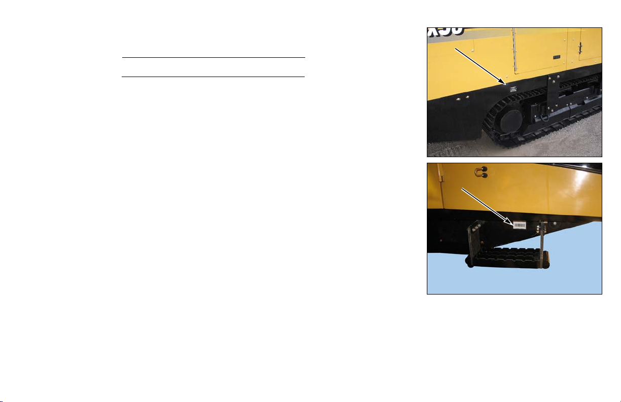
MACHINE IDENTIFICATION DECAL
This decal provides identification of the model and 17-digit identification number.
The barcode contains the machine’s VIN number and can be scanned with any
barcode reading device.
D60x90 Navigator HDD Receiving and Delivery Report v
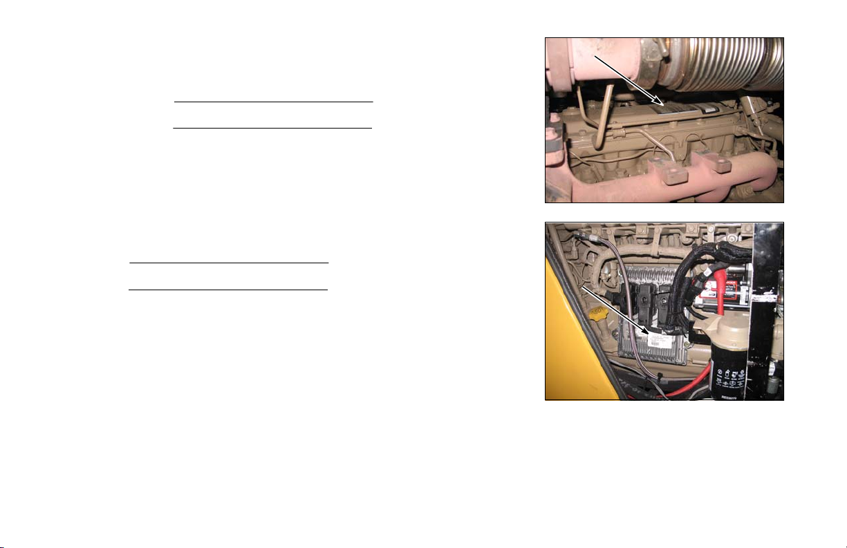
ENGINE IDENTIFICATION NUMBER - RECORD
On top of engine
Engine Model Number
Engine Serial Number
ENGINE CONTROL UNIT IDENTIFICATION NUMBER - RECORD
Model Number
Serial Number
vi Receiving and Delivery Report D60x90 Navigator HDD

DRILLING FLUID PUMP IDENTIFICATION NUMBER - RECORD
Model Number
Serial Number
D60x90 Navigator HDD Receiving and Delivery Report vii

This page intentionally left blank.

Table of Contents
Receiving and Delivery Report . . . . . . . . . . . . . . . . . . . . .i
Dealer Prep . . . . . . . . . . . . . . . . . . . . . . . . . . . . . . . . . . . . . . . . . i
Engine. . . . . . . . . . . . . . . . . . . . . . . . . . . . . . . . . . . . . . . . . . ii
Hydraulics . . . . . . . . . . . . . . . . . . . . . . . . . . . . . . . . . . . . . . . ii
Delivery . . . . . . . . . . . . . . . . . . . . . . . . . . . . . . . . . . . . . . . . . . . iii
Dealer/Owner Information . . . . . . . . . . . . . . . . . . . . . . . . . . . . . iv
Machine Identification Number - Record . . . . . . . . . . . . . . . . . . v
Machine Identification Decal . . . . . . . . . . . . . . . . . . . . . . . . . . . v
Engine Identification Number - Record . . . . . . . . . . . . . . . . . . . vi
Engine Control Unit Identification Number - Record . . . . . . . . . vi
Safety Messages . . . . . . . . . . . . . . . . . . . . . . . . . . . . . 10-1
Safety Symbol Explanation . . . . . . . . . . . . . . . . . . . . . . . . . .10-1
Fire Extinguisher . . . . . . . . . . . . . . . . . . . . . . . . . . . . . . . . . . 10-4
Welding Precautions. . . . . . . . . . . . . . . . . . . . . . . . . . 11-1
Welding Alert - Electronic Components . . . . . . . . . . . . . . . . . 11-1
Intended Use . . . . . . . . . . . . . . . . . . . . . . . . . . . . . . . . 15-1
Controls . . . . . . . . . . . . . . . . . . . . . . . . . . . . . . . . . . . . 20-1
Controls Locations . . . . . . . . . . . . . . . . . . . . . . . . . . . . . . . . .20-1
Top Panel Control . . . . . . . . . . . . . . . . . . . . . . . . . . . . . . . . . 20-1
Left Panel Controls . . . . . . . . . . . . . . . . . . . . . . . . . . . . . . . .20-2
Right Panel Controls . . . . . . . . . . . . . . . . . . . . . . . . . . . . . . .20-3
Right Joystick. . . . . . . . . . . . . . . . . . . . . . . . . . . . . . . . . . . . .20-4
Left Joystick . . . . . . . . . . . . . . . . . . . . . . . . . . . . . . . . . . . . . .20-4
Remote Control . . . . . . . . . . . . . . . . . . . . . . . . . . . . . . . . . . . 20-5
Tethered Secondary Remote Control (S/N 138 -). . . . . . . . . 20-6
Remote Lockout Transmitter. . . . . . . . . . . . . . . . . . . . . . . . . 20-7
Start/Stop Buttons . . . . . . . . . . . . . . . . . . . . . . . . . . . . . . . . . 20-7
Local Lockout Buttons. . . . . . . . . . . . . . . . . . . . . . . . . . . . . . 20-8
Strike Alert Controls . . . . . . . . . . . . . . . . . . . . . . . . . . . . . . . . 20-9
Strike Alert - Indicators and Controls . . . . . . . . . . . . . . 20-11
Indicators on Display Screen . . . . . . . . . . . . . . . . . . . . 20-11
Remote Lockout Controls . . . . . . . . . . . . . . . . . . . . . . . . . . 20-13
Remote Transmitter Controls . . . . . . . . . . . . . . . . . . . . . . . 20-13
Indicator Lights. . . . . . . . . . . . . . . . . . . . . . . . . . . . . . . 20-14
Remote Lockout Machine Controls . . . . . . . . . . . . . . . . . . . 20-15
Indicator Lights on Control Panel . . . . . . . . . . . . . . . . . 20-15
Indicator Lights on Display Screen. . . . . . . . . . . . . . . . 20-16
Remote Lockout Indicators . . . . . . . . . . . . . . . . . . . . . 20-17
Remote Lockout Battery Charger . . . . . . . . . . . . . . . . . . . . 20-19
Non-Cab Machine . . . . . . . . . . . . . . . . . . . . . . . . . . . . 20-19
Cab Machine . . . . . . . . . . . . . . . . . . . . . . . . . . . . . . . . 20-20
Engine Controls . . . . . . . . . . . . . . . . . . . . . . . . . . . . . . . . . . 20-21
Engine Operation Controls . . . . . . . . . . . . . . . . . . . . . . . . . 20-21
Transport Controls . . . . . . . . . . . . . . . . . . . . . . . . . . . . . . . . 20-26
Transport Remote Control. . . . . . . . . . . . . . . . . . . . . . . . . . 20-26
Contrast . . . . . . . . . . . . . . . . . . . . . . . . . . . . . . . . . . . . 20-27
Backlight. . . . . . . . . . . . . . . . . . . . . . . . . . . . . . . . . . . . 20-27
Changing Radio Channel . . . . . . . . . . . . . . . . . . . . . . . 20-27
Remote Registration . . . . . . . . . . . . . . . . . . . . . . . . . . 20-28
D60x90 Navigator HDD Table of Contents ix

Remote Control Operating Range . . . . . . . . . . . . . . . . . 20-30
Transport Controls . . . . . . . . . . . . . . . . . . . . . . . . . . . . . . . 20-31
Transport with Tethered Remote (S/N 138 -) . . . . . . . . 20-34
Setup Controls . . . . . . . . . . . . . . . . . . . . . . . . . . . . . . . . . . . 20-35
Stabilizer Controls - Left Console . . . . . . . . . . . . . . . . . . . . 20-35
Rotary Stakedown Controls - Left Console. . . . . . . . . . . . . 20-36
Rack and Stabilizer Controls - Remote Controls . . . . . . . . 20-37
Drilling Controls . . . . . . . . . . . . . . . . . . . . . . . . . . . . . . . . . . 20-38
Drilling Controls - Rotation . . . . . . . . . . . . . . . . . . . . . . . . . 20-38
Drilling Controls - Thrust. . . . . . . . . . . . . . . . . . . . . . . . . . . 20-41
AutoDrill Controls . . . . . . . . . . . . . . . . . . . . . . . . . . . . . . . . 20-43
Rod Loader Controls. . . . . . . . . . . . . . . . . . . . . . . . . . . . . . 20-45
Rod Handling Components . . . . . . . . . . . . . . . . . . . . . . 20-48
Greaser. . . . . . . . . . . . . . . . . . . . . . . . . . . . . . . . . . . . . . . . 20-50
Accumulator Gauge . . . . . . . . . . . . . . . . . . . . . . . . . . . . . . 20-50
Power Vise Controls . . . . . . . . . . . . . . . . . . . . . . . . . . . . . . 20-51
Drilling Fluid Controls . . . . . . . . . . . . . . . . . . . . . . . . . . . . . 20-52
Wash Wand Controls. . . . . . . . . . . . . . . . . . . . . . . . . . . 20-54
Drill Station Controls . . . . . . . . . . . . . . . . . . . . . . . . . . . . . . 20-56
Operator Presence/Seat Controls. . . . . . . . . . . . . . . . . . . . 20-56
Work Lights. . . . . . . . . . . . . . . . . . . . . . . . . . . . . . . . . . . . . 20-57
Beacon (Option) . . . . . . . . . . . . . . . . . . . . . . . . . . . . . . . . . 20-57
Horn Keys. . . . . . . . . . . . . . . . . . . . . . . . . . . . . . . . . . . . . . 20-58
Engine Cover Latches . . . . . . . . . . . . . . . . . . . . . . . . . . . . 20-58
Radiator Grille Cover . . . . . . . . . . . . . . . . . . . . . . . . . . . 20-59
Auxiliary Outlets . . . . . . . . . . . . . . . . . . . . . . . . . . . . . . . . . 20-60
Cab Controls. . . . . . . . . . . . . . . . . . . . . . . . . . . . . . . . . . . . 20-61
Cab Door Latch . . . . . . . . . . . . . . . . . . . . . . . . . . . . . . . 20-61
Access . . . . . . . . . . . . . . . . . . . . . . . . . . . . . . . . . . . . . . . . 20-63
Step - Non-Cab Operator Station. . . . . . . . . . . . . . . . . . . . .20-64
Console Display . . . . . . . . . . . . . . . . . . . . . . . . . . . . . . 21-1
Menu Screen . . . . . . . . . . . . . . . . . . . . . . . . . . . . . . . . . . . . .21-2
Drill Screen. . . . . . . . . . . . . . . . . . . . . . . . . . . . . . . . . . . . . . .21-3
AutoDrill Screens . . . . . . . . . . . . . . . . . . . . . . . . . . . . . . 21-6
AutoDrill Off . . . . . . . . . . . . . . . . . . . . . . . . . . . . . . . . . 21-6
AutoDrill Speed Mode . . . . . . . . . . . . . . . . . . . . . . . . . 21-6
Engine Screen . . . . . . . . . . . . . . . . . . . . . . . . . . . . . . . . . . . .21-7
Diesel Particulate Filter (DPF) . . . . . . . . . . . . . . . . . . . . . . . .21-8
DPF Controls. . . . . . . . . . . . . . . . . . . . . . . . . . . . . . . . . . 21-8
Forced Regeneration . . . . . . . . . . . . . . . . . . . . . . . . . 21-10
Inhibit Generation. . . . . . . . . . . . . . . . . . . . . . . . . . . . 21-10
Auto Steer . . . . . . . . . . . . . . . . . . . . . . . . . . . . . . . . . . . . . .21-11
Drill Setup. . . . . . . . . . . . . . . . . . . . . . . . . . . . . . . . . . . . . . .21-12
Drilling Fluid . . . . . . . . . . . . . . . . . . . . . . . . . . . . . . . . . 21-12
Auto Stop . . . . . . . . . . . . . . . . . . . . . . . . . . . . . . . . . . . 21-13
Drilling Pressure . . . . . . . . . . . . . . . . . . . . . . . . . . . . . . 21-14
Wireline/Remote Lockout . . . . . . . . . . . . . . . . . . . . . . . 21-14
Units . . . . . . . . . . . . . . . . . . . . . . . . . . . . . . . . . . . . . . . 21-15
Calibration Screens . . . . . . . . . . . . . . . . . . . . . . . . . . . . . . .21-16
Machine/Engine Diagnostics . . . . . . . . . . . . . . . . . . . . . . . .21-17
Active Codes Screen. . . . . . . . . . . . . . . . . . . . . . . . . . . 21-17
Screen Brightness Settings . . . . . . . . . . . . . . . . . . . . . . . . .21-19
Software Information Screen. . . . . . . . . . . . . . . . . . . . . 21-19
DigiTrak Locating Program. . . . . . . . . . . . . . . . . . . . . 25-1
Navigation Screen . . . . . . . . . . . . . . . . . . . . . . . . . . . . . . . . .25-2
Locator Setup Screen . . . . . . . . . . . . . . . . . . . . . . . . . . . 25-3
Units Setup Screen . . . . . . . . . . . . . . . . . . . . . . . . . . . 25-4
x Table of Contents D60x90 Navigator HDD

Locating Screens . . . . . . . . . . . . . . . . . . . . . . . . . . . . . . 25-4
Version Screen . . . . . . . . . . . . . . . . . . . . . . . . . . . . . . . . 25-5
Lockout Procedure - Without Remote Lockout System 30-19
Resuming Operation after Lockout. . . . . . . . . . . . . . . . 30-19
Overview . . . . . . . . . . . . . . . . . . . . . . . . . . . . . . . . . . . 30-1
Remote Lockout Overview . . . . . . . . . . . . . . . . . . . . . . . . . . .30-1
Remote Lockout System Intended Use . . . . . . . . . . . . . . . . .30-1
Remote Lockout System Component Identification. . . . . . . .30-3
Remote Transmitter . . . . . . . . . . . . . . . . . . . . . . . . . . . . . . . .30-3
Warning Alarm . . . . . . . . . . . . . . . . . . . . . . . . . . . . . . . . 30-4
Power Button . . . . . . . . . . . . . . . . . . . . . . . . . . . . . . . . . 30-4
Run Button . . . . . . . . . . . . . . . . . . . . . . . . . . . . . . . . . . . 30-5
Lockout Button . . . . . . . . . . . . . . . . . . . . . . . . . . . . . . . . 30-5
Remote Lockout Indicators . . . . . . . . . . . . . . . . . . . . . . . . . .30-6
Fault Check/Processing Lights . . . . . . . . . . . . . . . . . . . . 30-6
Hydraulic Lockout or Engine Shutdown Option . . . . . . . . . . .30-7
Auxiliary Engine Shutdown for Hydraulic Disable . . . . . . 30-8
Remote Lockout Tests. . . . . . . . . . . . . . . . . . . . . . . . . . . . . . 30-9
Hydraulic Lockout Test . . . . . . . . . . . . . . . . . . . . . . . . . . 30-9
Engine Shutdown Test . . . . . . . . . . . . . . . . . . . . . . . . . 30-10
Remote Lockout Transmitter Registration . . . . . . . . . . . . . . 30-11
Loss of Remote Transmitter Signal . . . . . . . . . . . . . . . . . . . 30-13
Battery Condition . . . . . . . . . . . . . . . . . . . . . . . . . . . . . . . . .30-14
Low Battery. . . . . . . . . . . . . . . . . . . . . . . . . . . . . . . . . . 30-14
Discharged Battery . . . . . . . . . . . . . . . . . . . . . . . . . . . . 30-14
Recharge Battery . . . . . . . . . . . . . . . . . . . . . . . . . . . . . 30-14
Remote Lockout System - Start. . . . . . . . . . . . . . . . . . . . . .30-15
Remote Lockout System - Shut Down. . . . . . . . . . . . . . . . .30-15
Lockout Procedures. . . . . . . . . . . . . . . . . . . . . . . . . . . . . . . 30-16
Lockout Procedure - With Remote Lockout System . . . 30-16
Resuming Operation after Remote Lockout . . . . . . . . . 30-18
D60x90 Navigator HDD Table of Contents xi
Drill Rod and Tools. . . . . . . . . . . . . . . . . . . . . . . . . . . . . . . . 30-20
Drill Rod. . . . . . . . . . . . . . . . . . . . . . . . . . . . . . . . . . . . . . . . 30-20
Drill Tool Assemblies. . . . . . . . . . . . . . . . . . . . . . . . . . . . . . 30-21
Armor Drill Housing Assembly . . . . . . . . . . . . . . . . . . . 30-21
Armor Multi-Tool . . . . . . . . . . . . . . . . . . . . . . . . . . . . 30-23
Rotary Tooth Installation/Extraction - Gauntlet Bit . . 30-24
Locator System. . . . . . . . . . . . . . . . . . . . . . . . . . . . . . . . . . . 30-25
Reamer Installation . . . . . . . . . . . . . . . . . . . . . . . . . . . . . . . 30-25
Swivel. . . . . . . . . . . . . . . . . . . . . . . . . . . . . . . . . . . . . . 30-25
Reamer Carrier - Intended Use . . . . . . . . . . . . . . . . . . 30-25
Reamer Carrier Styles . . . . . . . . . . . . . . . . . . . . . . . . . 30-26
Reamer Carrier Components . . . . . . . . . . . . . . . . . . . . 30-26
Reamer Carrier - Install/Remove . . . . . . . . . . . . . . . . . 30-27
Reamer Carrier - Lift. . . . . . . . . . . . . . . . . . . . . . . . . . . 30-27
Turnbuckle - Adjust . . . . . . . . . . . . . . . . . . . . . . . . . . . 30-28
Reamer - Connect with Manually Threaded
Joint and Collar . . . . . . . . . . . . . . . . . . . . . . . . . . . . . 30-29
Reamer Carrier Wear Pads - Replace. . . . . . . . . . . . . 30-29
PVC Pipe Pulling (Option). . . . . . . . . . . . . . . . . . . . . . . . . . 30-30
Rod Loader Setup. . . . . . . . . . . . . . . . . . . . . . . . . . . . . . . . . 30-31
Rod Box - Load with Rod . . . . . . . . . . . . . . . . . . . . . . . 30-31
Rod Box - Remove. . . . . . . . . . . . . . . . . . . . . . . . . . . . 30-32
Rod Box - Install. . . . . . . . . . . . . . . . . . . . . . . . . . . . . . 30-33
Rod Box - Prepare . . . . . . . . . . . . . . . . . . . . . . . . . . . . 30-34
Automatic Functions . . . . . . . . . . . . . . . . . . . . . . . . . . . . . . 30-35
AutoDrill. . . . . . . . . . . . . . . . . . . . . . . . . . . . . . . . . . . . . . . . 30-35
AutoDrill - Set . . . . . . . . . . . . . . . . . . . . . . . . . . . . . . . . 30-35

AutoDrill - Pause/Resume . . . . . . . . . . . . . . . . . . . . . . . 30-36
Front Vise Function in Resuming AutoDrill . . . . . . . . . 30-36
Auto Steering . . . . . . . . . . . . . . . . . . . . . . . . . . . . . . . . . . . 30-37
Carve Steering Setup . . . . . . . . . . . . . . . . . . . . . . . . . . 30-38
Zone Steering Setup . . . . . . . . . . . . . . . . . . . . . . . . . . . 30-39
Rod Wrap . . . . . . . . . . . . . . . . . . . . . . . . . . . . . . . . . . . 30-41
Vise Operating Guidelines . . . . . . . . . . . . . . . . . . . . . . . . . 30-42
Antifreeze - Add to Drilling Fluid System . . . . . . . . . . . . . . 30-43
Preparation . . . . . . . . . . . . . . . . . . . . . . . . . . . . . . . . . .40-1
Preparing Personnel . . . . . . . . . . . . . . . . . . . . . . . . . . . . . . . 40-1
Operator Qualifications . . . . . . . . . . . . . . . . . . . . . . . . . . . . . 40-1
Safety Conscious Operators and Workers . . . . . . . . . . . 40-1
Training. . . . . . . . . . . . . . . . . . . . . . . . . . . . . . . . . . . . . . . . . 40-2
Warning Safety Signs and Operating Instructions . . . . . . . . 40-2
Radio Communication Requirements. . . . . . . . . . . . . . . . . . 40-3
Radio Communication to Stop Drilling Operation . . . . . . 40-4
Radio Communication to Resume Drilling Operation . . . 40-4
Personal Protection . . . . . . . . . . . . . . . . . . . . . . . . . . . . . . . 40-5
Sound and Vibration Levels. . . . . . . . . . . . . . . . . . . . . . . 40-6
Underground Utility Contact . . . . . . . . . . . . . . . . . . . . . . . . . 40-7
Electrical Shock Protection. . . . . . . . . . . . . . . . . . . . . . . . . . 40-8
Electrocution Prevention . . . . . . . . . . . . . . . . . . . . . . . . . 40-9
Electrically Insulated Gloves . . . . . . . . . . . . . . . . . . . . . 40-10
Electrically Insulated Boots . . . . . . . . . . . . . . . . . . . . . . 40-12
Strike Alert System Functions . . . . . . . . . . . . . . . . . . . . 40-13
Soil Conductivity . . . . . . . . . . . . . . . . . . . . . . . . . . . . . . 40-13
Preparing the Machine. . . . . . . . . . . . . . . . . . . . . . . . . . . . . 40-14
Operator Presence System . . . . . . . . . . . . . . . . . . . . . . . . 40-14
Remote Lockout System Preparation. . . . . . . . . . . . . . . . . 40-14
xii Table of Contents D60x90 Navigator HDD
Range - Test . . . . . . . . . . . . . . . . . . . . . . . . . . . . . . . . . 40-14
Remote Transmitter - Prepare . . . . . . . . . . . . . . . . . . . 40-14
Remote Lockout System - Test. . . . . . . . . . . . . . . . . . . 40-15
Preparing the Work Area. . . . . . . . . . . . . . . . . . . . . . . . . . . .40-16
Jobsite - Check . . . . . . . . . . . . . . . . . . . . . . . . . . . . . . . . . .40-16
Power Line Locator System . . . . . . . . . . . . . . . . . . . . . 40-16
Warning Cones . . . . . . . . . . . . . . . . . . . . . . . . . . . . . . . 40-17
Laws and Regulations - Check . . . . . . . . . . . . . . . . . . . . . .40-17
Planning the Bore. . . . . . . . . . . . . . . . . . . . . . . . . . . . . . . . .40-17
Operation . . . . . . . . . . . . . . . . . . . . . . . . . . . . . . . . . . . 50-1
Starting Procedure . . . . . . . . . . . . . . . . . . . . . . . . . . . . . . . . .50-1
Before Starting . . . . . . . . . . . . . . . . . . . . . . . . . . . . . . . . . . . .50-1
Accumulator Pressure - Check . . . . . . . . . . . . . . . . . . . . 50-1
Recharging Pressure . . . . . . . . . . . . . . . . . . . . . . . . . . . 50-1
Starting the Engine. . . . . . . . . . . . . . . . . . . . . . . . . . . . . . . . .50-2
Cold Weather Starting . . . . . . . . . . . . . . . . . . . . . . . . . . . . . .50-3
Engine. . . . . . . . . . . . . . . . . . . . . . . . . . . . . . . . . . . . . . . 50-3
Hydraulic Fluid . . . . . . . . . . . . . . . . . . . . . . . . . . . . . . . . 50-3
Cold Weather Start System. . . . . . . . . . . . . . . . . . . . . . . 50-3
Shutdown Procedure. . . . . . . . . . . . . . . . . . . . . . . . . . . . . . . .50-4
Transporting the Machine. . . . . . . . . . . . . . . . . . . . . . . . . . . .50-5
Driving the Machine . . . . . . . . . . . . . . . . . . . . . . . . . . . . . . . .50-5
Backup Warning Alarm . . . . . . . . . . . . . . . . . . . . . . . . . . 50-6
Driving the Machine with Remote Control . . . . . . . . . . . . 50-6
Safe Operating Slope . . . . . . . . . . . . . . . . . . . . . . . . . . . 50-7
Preparing for Transport . . . . . . . . . . . . . . . . . . . . . . . . . . . . .50-8
Driving Machine with Wireless Remote Control . . . . . . . 50-9

Driving Machine with Tethered Secondary
Remote Control . . . . . . . . . . . . . . . . . . . . . . . . . . . . . 50-10
Trailering the Machine . . . . . . . . . . . . . . . . . . . . . . . . . . . . . 50-11
Loading/Unloading . . . . . . . . . . . . . . . . . . . . . . . . . . . . 50-11
Retrieval. . . . . . . . . . . . . . . . . . . . . . . . . . . . . . . . . . . . . . . .50-13
Lifting Machine. . . . . . . . . . . . . . . . . . . . . . . . . . . . . . . . . . .50-13
Setup . . . . . . . . . . . . . . . . . . . . . . . . . . . . . . . . . . . . . . . . . . .50-14
Bore Path - Walk . . . . . . . . . . . . . . . . . . . . . . . . . . . . . . . . . 50-14
Drill Unit Setup. . . . . . . . . . . . . . . . . . . . . . . . . . . . . . . . . . .50-14
Strike Alert System - Test . . . . . . . . . . . . . . . . . . . . . . . . . .50-15
Machine - Anchor with Stakes . . . . . . . . . . . . . . . . . . . . . . .50-17
Locating Equipment - Prepare . . . . . . . . . . . . . . . . . . . . . . .50-18
Drilling Fluid Setup. . . . . . . . . . . . . . . . . . . . . . . . . . . . . . . . 50-18
Rod Wiper - Install . . . . . . . . . . . . . . . . . . . . . . . . . . . . . . . .50-19
Entrance and Exit Sites - Prepare . . . . . . . . . . . . . . . . . . . . 50-19
Warning Cones . . . . . . . . . . . . . . . . . . . . . . . . . . . . . . . . . . 50-20
Drilling Safety . . . . . . . . . . . . . . . . . . . . . . . . . . . . . . . . . . . .50-20
Read Overview Section . . . . . . . . . . . . . . . . . . . . . . . . . . . .50-20
Safety Precautions. . . . . . . . . . . . . . . . . . . . . . . . . . . . . . . .50-21
Utility Line Contact . . . . . . . . . . . . . . . . . . . . . . . . . . . . 50-21
Electrical Line. . . . . . . . . . . . . . . . . . . . . . . . . . . . . . . 50-21
After Utility Company Has Shut Off the Power . . . . . 50-23
Gas . . . . . . . . . . . . . . . . . . . . . . . . . . . . . . . . . . . . . . 50-23
Fiber Optic Cable . . . . . . . . . . . . . . . . . . . . . . . . . . . . 50-23
Before the Bore . . . . . . . . . . . . . . . . . . . . . . . . . . . . . . . . . . .50-24
Diesel Particulate Filter (DPF) Safety . . . . . . . . . . . . . . . . .50-25
Drill Rod - Flush . . . . . . . . . . . . . . . . . . . . . . . . . . . . . . . . . .50-28
Drill Rod - Lubricate . . . . . . . . . . . . . . . . . . . . . . . . . . . . . . .50-30
Drill Head - Connect. . . . . . . . . . . . . . . . . . . . . . . . . . . . . . . 50-30
D60x90 Navigator HDD Table of Contents xiii
During the Bore. . . . . . . . . . . . . . . . . . . . . . . . . . . . . . . . . . . 50-31
Begin Drilling . . . . . . . . . . . . . . . . . . . . . . . . . . . . . . . . . . . . 50-31
Drill Rods - Add to Drill String . . . . . . . . . . . . . . . . . . . . . . . 50-32
Drill Rod Row - Select . . . . . . . . . . . . . . . . . . . . . . . . . 50-35
Gauges - Monitor. . . . . . . . . . . . . . . . . . . . . . . . . . . . . . . . . 50-36
Obstructions - Investigate . . . . . . . . . . . . . . . . . . . . . . . . . . 50-37
Plugged Drill Rod . . . . . . . . . . . . . . . . . . . . . . . . . . . . . . . . 50-37
Exiting the Bore . . . . . . . . . . . . . . . . . . . . . . . . . . . . . . . . . . 50-38
Changing Tools at Remote Exit Pit . . . . . . . . . . . . . . . . . . . 50-38
Remote Lockout Use . . . . . . . . . . . . . . . . . . . . . . . . . . 50-39
Communication Requirements. . . . . . . . . . . . . . . . . . . 50-39
Reamer Carrier Use . . . . . . . . . . . . . . . . . . . . . . . . . . . 50-39
Swivel Use . . . . . . . . . . . . . . . . . . . . . . . . . . . . . . . . . . 50-40
Pullback Tool - Install . . . . . . . . . . . . . . . . . . . . . . . . . . 50-41
Resuming Operation . . . . . . . . . . . . . . . . . . . . . . . . . . 50-42
Pullback - Start . . . . . . . . . . . . . . . . . . . . . . . . . . . . . . . . . . 50-43
Drill Rod Row - Select . . . . . . . . . . . . . . . . . . . . . . . . . 50-46
Breaking Rod Joints - Safety Considerations. . . . . . . . 50-47
Trailing Rod While Pre-Reaming. . . . . . . . . . . . . . . . . . . . . 50-47
Swivel Use . . . . . . . . . . . . . . . . . . . . . . . . . . . . . . . . . . 50-48
Short-String Method of Adding Drill Rod
for Pre-Reaming . . . . . . . . . . . . . . . . . . . . . . . . . . . . 50-48
Resuming Operation . . . . . . . . . . . . . . . . . . . . . . . . . . 50-49
Pulling Back with Trailing Rod . . . . . . . . . . . . . . . . . . . 50-50
Push-Through Method of Adding Drill Rod
for Pre-Reaming . . . . . . . . . . . . . . . . . . . . . . . . . . . . 50-51
Resuming Operation . . . . . . . . . . . . . . . . . . . . . . . . . 50-52
Gauges - Monitor During Pullback . . . . . . . . . . . . . . . . . . . 50-53
After Each Bore. . . . . . . . . . . . . . . . . . . . . . . . . . . . . . . . . . . 50-54
Power Vises - Clean. . . . . . . . . . . . . . . . . . . . . . . . . . . 50-54

Drill Rods - Clean and Store . . . . . . . . . . . . . . . . . . . . . 50-55
Flushing Bentonite/Polymers from Drilling Fluid System 50-55
Machine - Wash. . . . . . . . . . . . . . . . . . . . . . . . . . . . . . . 50-56
Maintenance Intervals . . . . . . . . . . . . . . . . . . . . . . . . . . . . . .60-3
Supplemental Operations . . . . . . . . . . . . . . . . . . . . . .55-1
Jump-Starting. . . . . . . . . . . . . . . . . . . . . . . . . . . . . . . . . . . . . 55-1
Battery Explosion - Prevent . . . . . . . . . . . . . . . . . . . . . . . . . 55-1
Battery Burns - Prevent . . . . . . . . . . . . . . . . . . . . . . . . . . . . 55-2
Jump-Starting Procedure . . . . . . . . . . . . . . . . . . . . . . . . . . . 55-2
PBD7500 Portable Breakout Device . . . . . . . . . . . . . . . . . . . 55-4
Intended Use . . . . . . . . . . . . . . . . . . . . . . . . . . . . . . . . . . . . 55-4
Breakout Device Operation. . . . . . . . . . . . . . . . . . . . . . . . . . 55-5
Configurations . . . . . . . . . . . . . . . . . . . . . . . . . . . . . . . . . 55-8
Maintenance . . . . . . . . . . . . . . . . . . . . . . . . . . . . . . . . . . 55-8
Mud Motors. . . . . . . . . . . . . . . . . . . . . . . . . . . . . . . . . . . . . . . 55-8
Replacing Broken Drill Rod Underground. . . . . . . . . . . . . . 55-9
Drilling with Front Load Wireline Locator System . . . . . . 55-11
Initial Drill Rod Connection . . . . . . . . . . . . . . . . . . . . . . . . . 55-11
Adding Drill Rod . . . . . . . . . . . . . . . . . . . . . . . . . . . . . . . . . 55-13
Pullback . . . . . . . . . . . . . . . . . . . . . . . . . . . . . . . . . . . . . . . 55-14
Maintenance . . . . . . . . . . . . . . . . . . . . . . . . . . . . . . . . .60-1
Safety Signs Maintenance . . . . . . . . . . . . . . . . . . . . . . . . . . 60-1
Maintenance Manual . . . . . . . . . . . . . . . . . . . . . . . . . . . . . . 60-2
Hourmeter - Check for Maintenance Interval . . . . . . . . . . . . 60-2
Machine - Grease . . . . . . . . . . . . . . . . . . . . . . . . . . . . . . . . . 60-2
Recommended Fluids. . . . . . . . . . . . . . . . . . . . . . . . . . . . . . 60-2
Engine Maintenance Intervals . . . . . . . . . . . . . . . . . . . . . . . 60-2
xiv Table of Contents D60x90 Navigator HDD

Section 10: Safety Messages
General safety messages appear in this Safety Messages section. Specific safety messages are located in
appropriate sections of the manual where a potential hazard may occur if the instructions or procedures are not
followed.
A signal word “DANGER”, “WARNING”, or “CAUTION” is used with the safety alert symbol.
Safety signs with signal word “DANGER”, “WAR NING”, or “CAUTION” are located near specific hazards.
DANGER
WARNING
CAUTION
NOTICE
Indicates a hazardous situation that, if not avoided, will result in death or serious injury.
Indicates a hazardous situation that, if not avoided, could result in death or serious injury.
Indicates a hazardous situation that, if not avoided, could result in minor or moderate injury.
Indicates information considered important, but not hazard-related.
SAFETY SYMBOL EXPLANATION
This is the safety alert symbol. This symbol is used in combination with an exclamation mark or
other symbols to alert you to the potential for bodily injury or death.
WAR NING: Read Operator’s Manual and safety signs before operating machine.
D60x90 Navigator HDD Safety Messages 10-1

WAR NING: Check machine before operating. Machine must be in good operating condition
and all safety equipment installed and functioning properly.
WAR NING: Wear pers onal prote ctive equipment. Dress properly. Refer to “Personal
Protection,” page 40-5.
WAR NING: Keep spectators away.
WAR NING: Engine exhaust can asphyxiate. Operate only outdoors.
WAR NING: Use Shutdown Procedure before servicing, cleaning, repairing or transporting
machine. Refer to page 50-4.
10-2 Safety Messages D60x90 Navigator HDD

WAR NING: Pressurized fluid can penetrate body tissue and result in serious injury or
death. Leaks can be invisible. Keep away from any suspected leaks. Relieve pressure in the
hydraulic system before searching for leaks, disconnecting hoses, or performing any other
work on the system. If you must pressurize the system to find a suspected leak, use an
object such as a piece of wood or cardboard rather than your hands. When loosening a
fitting where some residual pressure may exist, slowly loosen the fitting until oil begins to
leak. Wait for leaking to stop before disconnecting the fitting. Fluid injected under the skin
must be removed immediately by a surgeon familiar with this type of injury.
WAR NING: Fuel and fumes can explode and burn.
Shut off engine before refueling. No flame. No smoking.
WAR NING: Hot fluid under pressure can scald.
Allow engine to cool before opening radiator cap.
D60x90 Navigator HDD Safety Messages 10-3
WAR NING: When HEST (High Exhaust System Temperature) Light is displayed, the
1
exhaust gas temperature could exceed 1100°F (600°C) during regeneration. High
temperature may result in fire, burn, or explosion hazards, which may result in personal
injury or death. Do not expose flammable material or explosive atmospheres to exhaust gas
or to exhaust system components during regeneration.
WAR NING: To prevent fi res, routinely cle ar any com bustible m ate rial from the engine
exhaust system. Tier 4 Interim / Stage IIIB emission compliant exhaust systems use
extreme high temperature that can ignite combustible material.
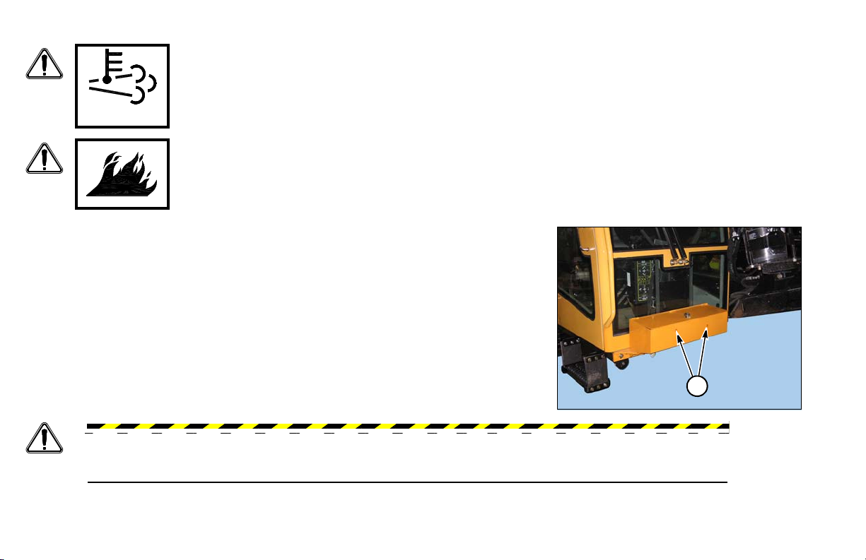
FIRE EXTINGUISHER
A fire extinguisher (not supplied with machine) can be mounted to the remote
control box (1).
WAR NING: Fa i l ure to follow any of the precedi ng safety instructions or those that follow within
this manual, could result in serious injury or death. This machine is to be used only for those
purposes for which it was intended as explained in this Operator’s Manual.
10-4 Safety Messages D60x90 Navigator HDD
Section 11: Welding Precautions
2
1
3
4
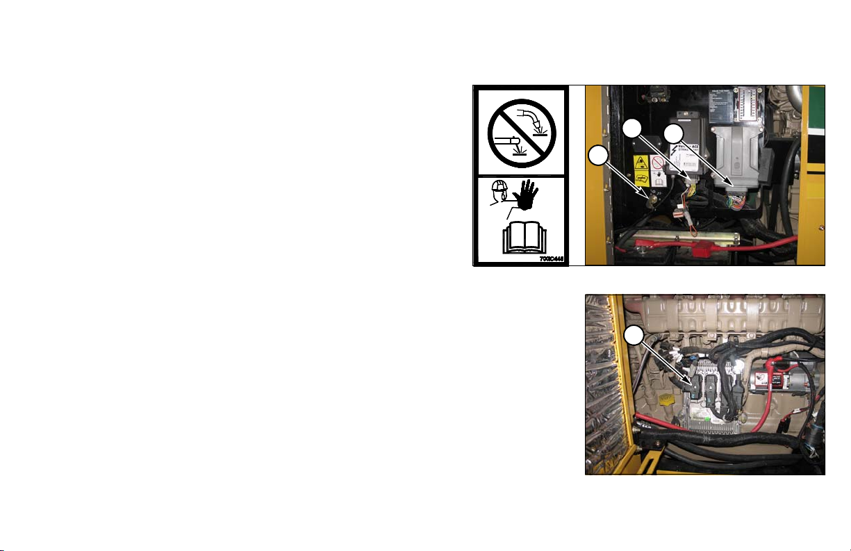
WELDING ALERT - ELECTRONIC COMPONENTS
NOTICE: Electronic modules and controllers will be damaged from
stray voltages and currents generated during welding if not
unplugged before welding.
To prevent exte nsive and cos tly damage to th e electric al
components:
Step 1: Turn Battery Disconnect Switch (1) to DISCONNECT.
NOTICE: Disconnecting the battery ground with the battery
disconnect switch will not prevent damage to the electronic
components during welding. Each of the modules must have the
electrical connector unplugged from the module.
Step 2: Unplug Strike Alert (2) and pump controller (POM) modules (3).
Step 3: Unplug three engine ECUs (4).
D60x90 Navigator HDD Welding Precautions 11-1
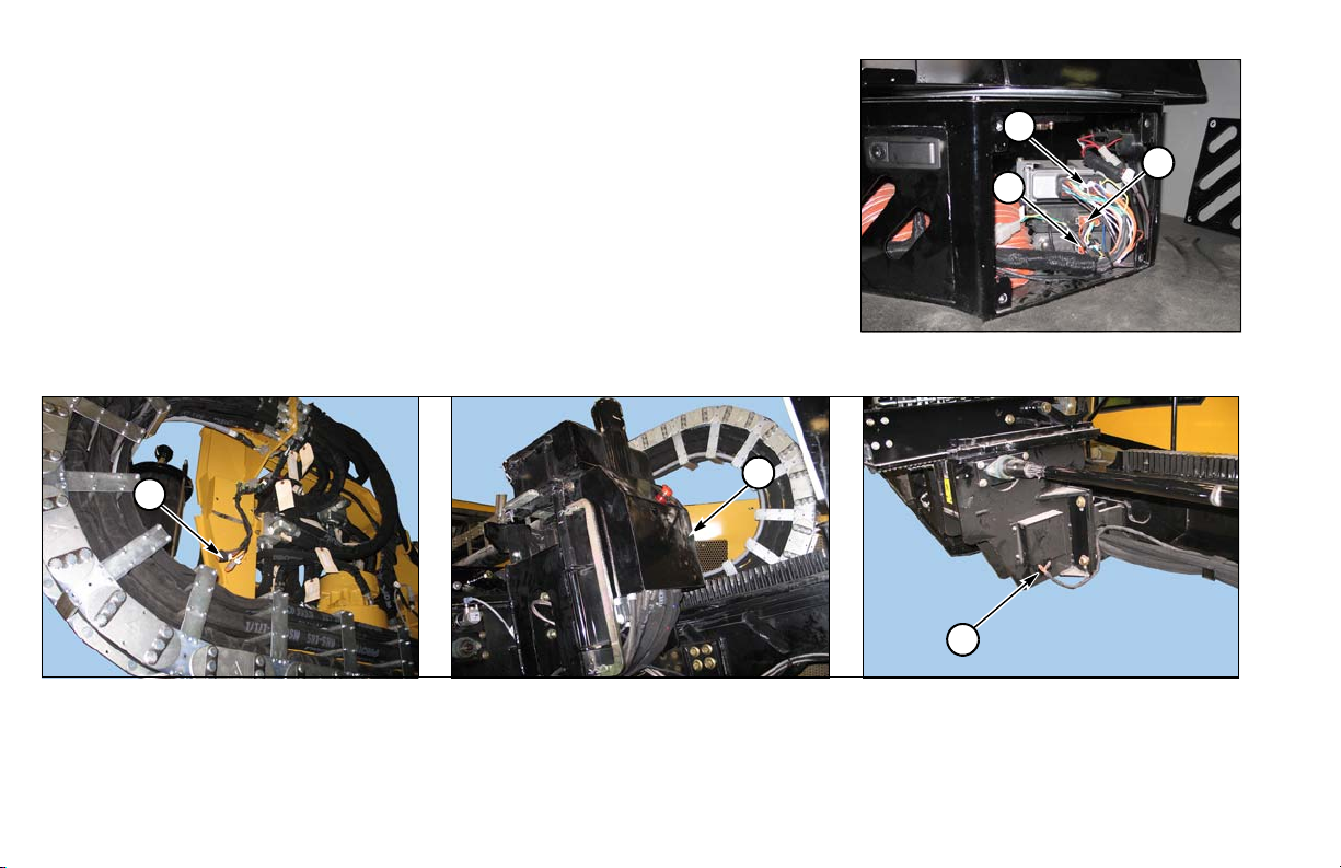
Step 4: Under the seat, unplug three connectors, to the cab controller (5), the
5
6
7
8
9
10
Remote Lockout Controller (RLC) (6) and the DCIM module (7).
In cab machine, access through foot panel in front of operator seat; in noncab machine, tip seat forward and lift panel.
Step 5: Unplug carriage control unit (CCU) (8), rack output controller (ROM) (9), and vise controller (VOM) (10).
11-2 Welding Precautions D60x90 Navigator HDD

Section 15: Intended Use
The Vermeer D60x90 Navigator Horizontal Directional Drill is designed solely to create horizontal bores
through the earth. Utilities are typically installed in these underground bores during pullback.
Always use the machine in accordance with the instructions contained in this Operator’s Manual, safety signs
on the machine, and other material provided by Vermeer Corporation.
Correct maintenance and repair is essential for safety, and for efficient operation of the machine. Do not use the
machine if it is not in suitable operating condition.
D60x90 Navigator HDD Intended Use 15-1

This page intentionally left blank.
 Loading...