

Vermeer D20x22 Series II Maintenance Manual
D20x22 Series II
Navigator® Horizontal Directional Drill
Maintenance
Manual
D20x22_Series_ii_m2_01
Serial No. 1001 Order No. 105400CD5

Introduction
This manual explains the proper operation of your machine. Study and understand these instructions thoroughly before operating or
maintaining the machine. Failure to do so could result in personal injury or equipment damage. Consult your Vermeer dealer if you
do not understand the instructions in this manual, or need additional information.
The instructions, illustrations, and specifications in this manual are based on the latest information available at time of publication.
Your machine may have product improvements and features not yet contained in this manual.
The maintenance intervals are based on normal operating conditions. When operating under severe conditions, the maintenance
intervals should be shortened.
To provide a better view, some photographs or illustrations in the maintenance sections may show the machine shields removed.
Never operate the machine with the shields removed - keep all shields in place. If removing a shield is necessary, return it
to its operating position before operating the machine.
Vermeer Corporation reserves the right to make changes at any time without notice or obligation.
This manual is supplied with each machine. Refer to it for all lubrication and maintenance procedures. Keep this manual with the
machine for ready reference. Store it in a protected location when not in use.
Additional copies of the manuals, and Operations and Safety video, are available from your dealer. Reorder numbers are listed on the
front covers of the manuals and on the video..
Copies of this manual, and the Operations and Safety video, are available in Spanish from your dealer.
Su distribuidor dispone de ejemplares en español de este manual y del vídeo de Operaciones y Seguridad.
NOTICE TO OWNER
You are requested to notify Vermeer Corporation when you have purchased a used Vermeer machine. Notify the Customer Data
Department by telephone: 800-829-0051 or 641-628-3141; email: customerdata@vermeer.com; internet: www.vermeer.com or
www.vermeerag.com; or letter: Customer Data Dept., Vermeer Corporation, PO Box 200, Pella IA 50219 USA. Upon request, an
owner of a used Vermeer machine will receive one free set of Operator’s, Maintenance and Parts manuals.
D20x22 Series II HDD Maintenance

SERVICE
Service instructions are contained in a separate service manual. Service manuals can be obtained by contacting your Vermeer dealer.
If you are considering servicing the machine without the assistance of a Vermeer dealer, remember this is a complex machine which
often involves complex service procedures.
There are also many components which are not user-serviceable. Do not attempt any service which you do not fully understand, nor
any service that you cannot do accurately and safely with proper tools and equipment. If you encounter a problem that you do not
understand or cannot solve, contact your Vermeer dealer.
TRADEMARKS
VERMEER, VERMEER Logo, NAVIGATOR and BIOSTICK are trademarks of Vermeer Manufacturing Company.
MERCON is a trademark of Ford Motor Company.
DEXRON is a trademark of General Motors Corporation.
KUBOTA is a trademark of Kubota, Ltd.
FLEETGUARD is a trademark of Fleetguard, Inc.
D20x22 Series II HDD Maintenance

This page intentionally left blank.

Table of Contents
Safety Messages . . . . . . . . . . . . . . . . . . . . . . . . . . . . 10-1
Safety Symbol Explanation . . . . . . . . . . . . . . . . . . . . . . . . . .10-1
Drilling Fluid Pump Crankcase Oil Level - Check . . . . . . . . . 25-3
Rotation Gearbox Oil - Check . . . . . . . . . . . . . . . . . . . . . . . 25-3
Power Vise - Grease . . . . . . . . . . . . . . . . . . . . . . . . . . . . . . 25-4
Shutdown Procedure . . . . . . . . . . . . . . . . . . . . . . . . . 11-1
Maintenance - 100 Service Hours . . . . . . . . . . . . . . . 30-1
Welding Precautions . . . . . . . . . . . . . . . . . . . . . . . . . 12-1
Welding Alert - Electronic Components . . . . . . . . . . . . . . . .12-1
Maintenance - 10 Service Hours or Daily . . . . . . . . . 20-1
Machine - Grease . . . . . . . . . . . . . . . . . . . . . . . . . . . . . . . . .20-1
Engine Maintenance . . . . . . . . . . . . . . . . . . . . . . . . . . . . . . .20-1
Fluid Levels - Check . . . . . . . . . . . . . . . . . . . . . . . . . . . . . . . 20-1
Engine Oil Level - Check . . . . . . . . . . . . . . . . . . . . . . . . 20-1
Hydraulic Fluid Level - Check . . . . . . . . . . . . . . . . . . . . . 20-2
Coolant Level - Check . . . . . . . . . . . . . . . . . . . . . . . . . . 20-3
Fuel Tank - Fill . . . . . . . . . . . . . . . . . . . . . . . . . . . . . . . . 20-4
Air Cleaner Restriction Indicator - Check . . . . . . . . . . . . . . . 20-5
Drill Rod Care . . . . . . . . . . . . . . . . . . . . . . . . . . . . . . . . . . . .20-5
Auto Greaser - Adjust/Check/Refill . . . . . . . . . . . . . . . . . . . . 20-6
R.A.T.T. Tool . . . . . . . . . . . . . . . . . . . . . . . . . . . . . . . . . . . .20-7
Tool - Oil . . . . . . . . . . . . . . . . . . . . . . . . . . . . . . . . . . . . . 20-7
Rotation Sensor Phase - Verify . . . . . . . . . . . . . . . . . . . 20-8
Maintenance - 50 Service Hours or Weekly . . . . . . . 25-1
Fuel/Water Separator - Drain . . . . . . . . . . . . . . . . . . . . . . . . 25-1
Engine Oil and Filter - Initial Change . . . . . . . . . . . . . . . . . .25-1
Control Levers Linkage - Oil . . . . . . . . . . . . . . . . . . . . . . . . . 25-2
Track Gearbox Oil Level - Check . . . . . . . . . . . . . . . . . . . . . 25-2
D20x22 Series II HDD Maintenance Table of Contents i
Cooling System - Check . . . . . . . . . . . . . . . . . . . . . . . . . . . . 30-1
Drilling Fluid System - Check . . . . . . . . . . . . . . . . . . . . . . . . 30-1
Drilling Fluid Pump Oil - Initial Change . . . . . . . . . . . . . . . . . 30-1
Control Levers - Check . . . . . . . . . . . . . . . . . . . . . . . . . . . . . 30-1
Overall Machine - Check . . . . . . . . . . . . . . . . . . . . . . . . . . . 30-2
Safety Signs Maintenance . . . . . . . . . . . . . . . . . . . . . . . . . . 30-2
Indicator Lights - Check . . . . . . . . . . . . . . . . . . . . . . . . . . . . 30-3
Emergency Stop Switch - Check . . . . . . . . . . . . . . . . . . . . . 30-3
Neutral Start Interlock - Check . . . . . . . . . . . . . . . . . . . . . . . 30-3
Operator Presence System - Check . . . . . . . . . . . . . . . . . . . 30-4
Hydraulic System - Check . . . . . . . . . . . . . . . . . . . . . . . . . . 30-5
Ground Drive System - Inspect . . . . . . . . . . . . . . . . . . . . . . 30-6
Track Chain Tension . . . . . . . . . . . . . . . . . . . . . . . . . . . 30-6
Maintenance - 250 Service Hours . . . . . . . . . . . . . . . 35-1
Engine Maintenance . . . . . . . . . . . . . . . . . . . . . . . . . . . . . . . 35-1
Cooling System Additive - Add . . . . . . . . . . . . . . . . . . . . . . . 35-1
Hydraulic Fluid Filter - Initial Replacement . . . . . . . . . . . . . . 35-2
R,A.T.T. Tool Oil - Change . . . . . . . . . . . . . . . . . . . . . . . . . . 35-2
Maintenance - 500 Service Hours . . . . . . . . . . . . . . . 40-1
Engine Maintenance . . . . . . . . . . . . . . . . . . . . . . . . . . . . . . . 40-1
Fuel Tank - Drain . . . . . . . . . . . . . . . . . . . . . . . . . . . . . . . . . 40-1

Fuel Filters - Replace . . . . . . . . . . . . . . . . . . . . . . . . . . . . . . 40-2
Engine Oil and Filter - Change . . . . . . . . . . . . . . . . . . . . . . 40-3
Battery Electrolyte Level and Terminals - Check/Clean . . . 40-4
Battery Terminals - Clean/Check Electrolyte Level . . . . . 40-5
Ground Drive Speed - Check . . . . . . . . . . . . . . . . . . . . . . . . 40-6
Park Brake - Check . . . . . . . . . . . . . . . . . . . . . . . . . . . . . . . 40-6
Hydraulic Fluid Filter - Replace . . . . . . . . . . . . . . . . . . . . . . 40-7
Hydraulic Fluid Flow Direction . . . . . . . . . . . . . . . . . . . . . 40-8
Drilling Fluid Pump Oil - Change . . . . . . . . . . . . . . . . . . . . . 40-8
Maintenance - 1000 Service Hours . . . . . . . . . . . . . . .45-1
Engine Maintenance . . . . . . . . . . . . . . . . . . . . . . . . . . . . . . 45-1
Planetary Gearbox Oil - Change . . . . . . . . . . . . . . . . . . . . . 45-1
Cooling System - Drain and Clean . . . . . . . . . . . . . . . . . . . 45-2
Cooling System - Refill . . . . . . . . . . . . . . . . . . . . . . . . . . 45-3
Hydraulic Fluid - Change . . . . . . . . . . . . . . . . . . . . . . . . . . . 45-4
Hydraulic Fluid - Drain . . . . . . . . . . . . . . . . . . . . . . . . . . . 45-4
Strainer - Remove . . . . . . . . . . . . . . . . . . . . . . . . . . . . . . 45-4
Strainer - Clean and Inspect . . . . . . . . . . . . . . . . . . . . . . 45-5
Strainer - Install . . . . . . . . . . . . . . . . . . . . . . . . . . . . . . . . 45-5
Tank - Fill . . . . . . . . . . . . . . . . . . . . . . . . . . . . . . . . . . . . . 45-5
Additional Periodic Maintenance . . . . . . . . . . . . . . . .46-1
Engine Maintenance . . . . . . . . . . . . . . . . . . . . . . . . . . . . . . 46-1
2000 Service Hours or Yearly . . . . . . . . . . . . . . . . . . . . . 46-1
2000 Service Hours or 2 Years . . . . . . . . . . . . . . . . . . . . 46-1
3000 Service Hours or 2 Years . . . . . . . . . . . . . . . . . . . . 46-1
6000 Service Hours or 6 Years . . . . . . . . . . . . . . . . . . . . 46-1
Engine Maintenance . . . . . . . . . . . . . . . . . . . . . . . . . . . . . . .50-1
Engine Compartment - Clean . . . . . . . . . . . . . . . . . . . . . . . .50-1
Battery - Replace . . . . . . . . . . . . . . . . . . . . . . . . . . . . . . . . .50-1
Air Cleaner Elements - Replace . . . . . . . . . . . . . . . . . . . . . .50-3
Track Tension - Adjust . . . . . . . . . . . . . . . . . . . . . . . . . . . . .50-4
Rod Guide Plate - Replace . . . . . . . . . . . . . . . . . . . . . . . . . .50-5
Vise Dies - Replace . . . . . . . . . . . . . . . . . . . . . . . . . . . . . . . .50-6
Front Vise . . . . . . . . . . . . . . . . . . . . . . . . . . . . . . . . . . . . 50-6
Rear Vise . . . . . . . . . . . . . . . . . . . . . . . . . . . . . . . . . . . . 50-7
Stakedown Drivers - Remove/Install . . . . . . . . . . . . . . . . . . .50-9
Rotation Sensor Phase - Adjust . . . . . . . . . . . . . . . . . . . . .50-10
Storage . . . . . . . . . . . . . . . . . . . . . . . . . . . . . . . . . . . . . . . .50-12
Preparing for Storage . . . . . . . . . . . . . . . . . . . . . . . . . . 50-12
Removing from Storage . . . . . . . . . . . . . . . . . . . . . . . . 50-12
Troubleshooting . . . . . . . . . . . . . . . . . . . . . . . . . . . . . 60-1
Engine System . . . . . . . . . . . . . . . . . . . . . . . . . . . . . . . . . . .60-1
Electrical System . . . . . . . . . . . . . . . . . . . . . . . . . . . . . . . . . .60-1
Hydraulic System . . . . . . . . . . . . . . . . . . . . . . . . . . . . . . . . .60-2
Drilling Fluid System . . . . . . . . . . . . . . . . . . . . . . . . . . . . . . .60-3
Strike Alert System . . . . . . . . . . . . . . . . . . . . . . . . . . . . . . . .60-4
Remote Lockout System . . . . . . . . . . . . . . . . . . . . . . . . . . . .60-5
Specifications . . . . . . . . . . . . . . . . . . . . . . . . . . . . . . . 65-1
Lubricants . . . . . . . . . . . . . . . . . . . . . . . . . . . . . . . . . . . . . . .65-1
Machine Specifications . . . . . . . . . . . . . . . . . . . . . . . . . . . . .65-3
Maintenance As Required . . . . . . . . . . . . . . . . . . . . . .50-1
ii Table of Contents D20x22 Series II HDD Maintenance
Section 10: Safety Messages
General safety messages appear in this Safety Messages section. Specific safety messages are located in
appropriate sections of the manual where a potential hazard may occur if the instructions or procedures are not
followed.
A signal word “DANGER”, “WARNIN G”, or “CAUTION” is used with the safety alert symbol.
Safety signs with signal word “DANGER”, “WARNING ”, or “CAUTION” are located near specific hazards.
DANGER
WARNING
CAUTION
Indicates a hazardous situation that, if not avoided, will result in death or serious injury.
Indicates a hazardous situation that, if not avoided, could result in death or serious injury.
Indicates a hazardous situation that, if not avoided, could result in minor or moderate injury.
SAFETY SYMBOL EXPLANATION
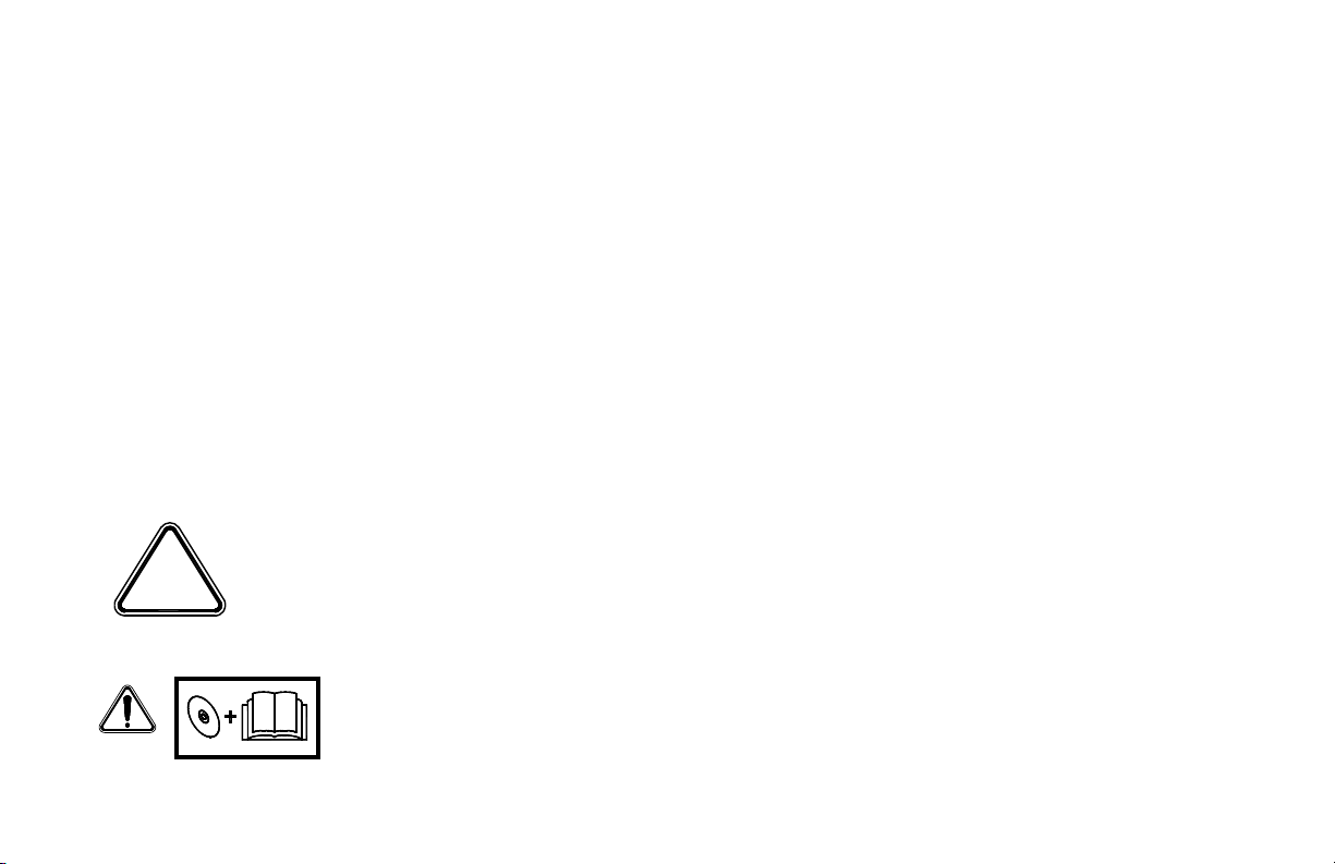
This is the safety alert symbol. This symbol is used in combination with an
exclamation mark or other symbols to alert you to the potential for bodily injury
or death.
WAR NING: Read Operator’s Manual and safety signs, and watch the operations and safety
video, before operating machine.
D20x22 Series II HDD Maintenance Safety Messages 10-1
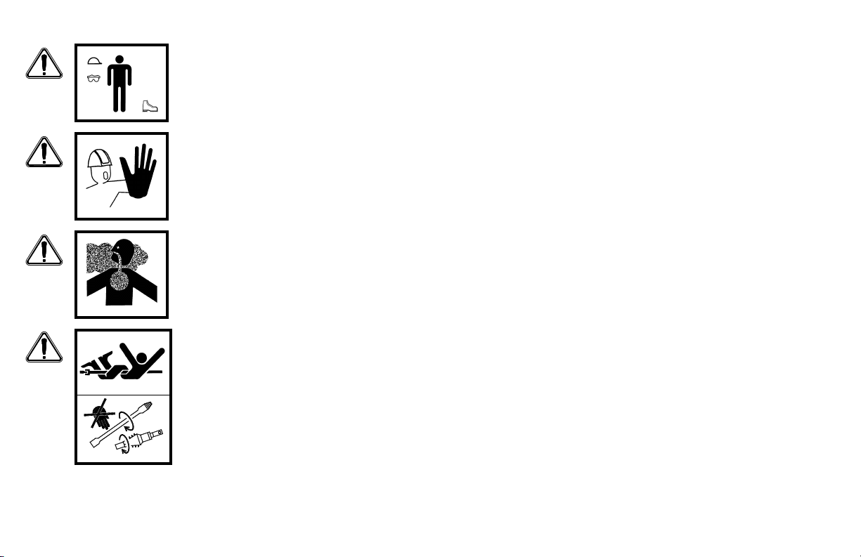
WAR NING: Wear personal protective equipment. Wear close-fitting clothing and confine
long hair. Always wear a hard hat, safety glasses, and safety shoes.
WAR NING: Keep spectators away.
WAR NING: Exhaust fumes can be fatal.
If operating in an enclosed area, remove exhaust fumes with an exhaust pipe extension to
the outside.
DANGER: Rotating drill string or cutters can kill.
Stay away from rotating drill rod and cutting tool.
10-2 Safety Messages D20x22 Series II HDD Maintenance
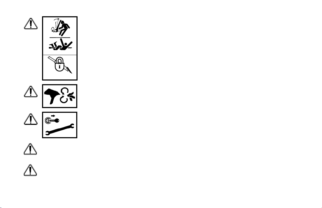
WARN ING: Rotating drill string can kill. Unexpected start-up possible.
Lock out before working on drill string.
WARNING: Keep hands, feet, and clothing away from power-driven parts. Keep shields in
place and properly secured.
WARNING: Use Shutdown Procedure before servicing, cleaning, repairing or transporting
machine. Refer to page 11-1.
WAR NING: Make no modifications to this equipment unless specifically recommended by Vermeer
Corporation.
WAR NING: Be sure that all safety devices, including shields, are installed and functioning properly after
servicing the machine.
D20x22 Series II HDD Maintenance Safety Messages 10-3
WARNING: Fa ilure to f o l l o w an y o f the preceding safety instructions or those that follow within
this manual, could result in serious injury or death. This machine is to be used only for those
purposes for which it was intended as explained in the Operator’s Manual.
10-4 Safety Messages D20x22 Series II HDD Maintenance

Section 11: Shutdown Procedure
Step 1: Shut off drilling fluid pump.
Step 2: Reduce engine speed to idle.
Step 3: Wai t two m inutes to shut off en gine w hen shutting down after operating at full power.
Step 4: Shut off engine and remove key.
For your safety and the safety of others, use shutdown procedure before working on the machine for any reason,
including servicing, cleaning, unplugging, or inspecting.
If working on the drill string or drill tools at a remote location away from the machine, follow “Lockout
Procedure - With Remote Lockout,” or “Lockout Procedure - Without Remote Lockout System,” in the Overview
Section of the Operator’s Manual.
A variation of the above procedure may be used if instructed within this manual or if an emergency requires it.
D20x22 Series II HDD Maintenance Shutdown Procedure 11-1

This page intentionally left blank.
Section 12: Welding Precautions
1
2
3
4
5
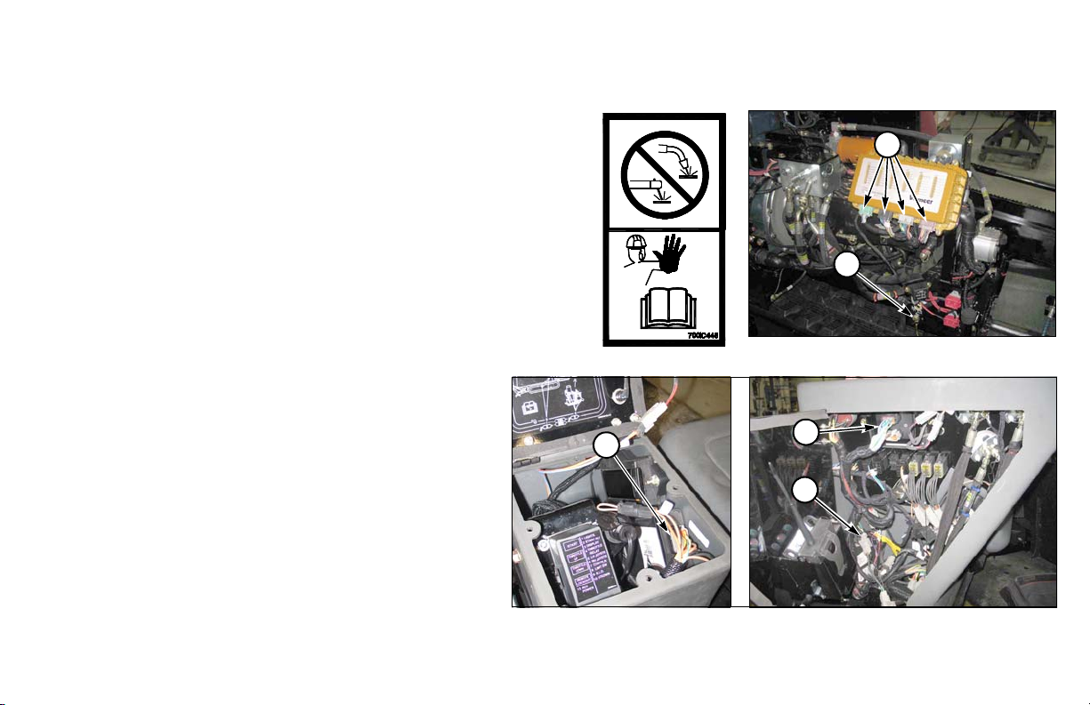
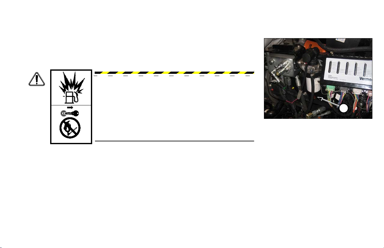
WELDING ALERT - ELECTRONIC COMPONENTS
NOTICE: Electronic modules and controllers will be damaged
from stray voltages and currents generated during welding if
not unplugged before welding.
To prevent extensive and costly damage to the electrical
components:
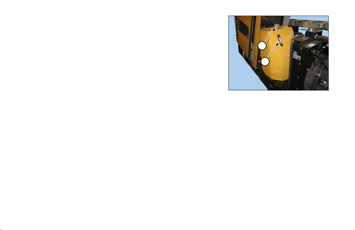
Step 1: Turn Battery Disconnect Switch (1) to DISCONNECT.
NOTICE: Disconnecting the battery ground with the battery
disconnect switch will not prevent damage to the electronic
components during welding. Each of the modules must have the
electrical connector unplugged from the module.
Step 2: Unplug controller (2).
Step 3: Unplug Remote Lockout (RLO) module (3)
(in compartment to the left of seat), Strike
Alert module (4) and DP10 display (5) (in
right hand control panel).
D20x22 Series II HDD Maintenance Welding Precautions 12-1
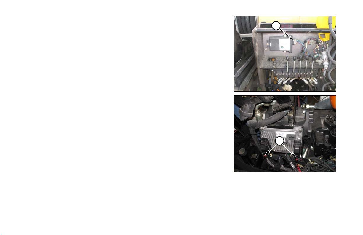
Step 4: Unplug Tethered Transport Control (6).
6
7
Step 5: Tier 4 Interim/Stage IIIB engine: unplug engine ECU (7), located on left
side of engine.
Step 6: Connect welding ground as close to work as possible.
12-2 Welding Precautions D20x22 Series II HDD Maintenance

Section 20: Maintenance - 10 Service Hours or Daily
1
2
MACHINE - GREASE
As a general rule, grease machine after it is shut down for the day. This protects the metal under the seals from
corrosion caused by condensation as the temperature drops.
Ensure all fittings and grease applicator nozzle are clean before applying grease. If any grease fittings are
missing, replace them immediately.
ENGINE MAINTENANCE
•Check fluid levels.
•Check air cleaner indicator.
• Perform walk-around inspection.
Refer to the Engine Operation Manual supplied with the machine for engine maintenance information.
FLUID LEVELS - CHECK
Check fluid levels daily before operating the machine. Also, inspect machine and
make any necessary adjustments and repairs before starting the engine. Refer to the
Engine Operation Manual.
Engine Oil Level - Check
With engine level, fill to full mark on dipstick. Do not overfill.
(1) Oil Fill Cap
(2) Oil Dipstick
D20x22 Series II HDD Maintenance 10 Service Hours or Daily 20-1
Hydraulic Fluid Level - Check
2
1
Clean hydraulic fluid is very important. Do not spill dirt or other contaminants into
the tank. Filter all hydraulic fluid through a 5-micron filter before adding it to the
tank.
Keep tank filled to sight gauge level. Machine must be level and in transport position.
Refer to “Lubricants,” page 65-1.
Step 1: Remove fill cap (1).
Step 2: Fill to upper half of sight gauge level (2).
Step 3: Install fill cap.
20-2 10 Service Hours or Daily D20x22 Series II HDD Maintenance
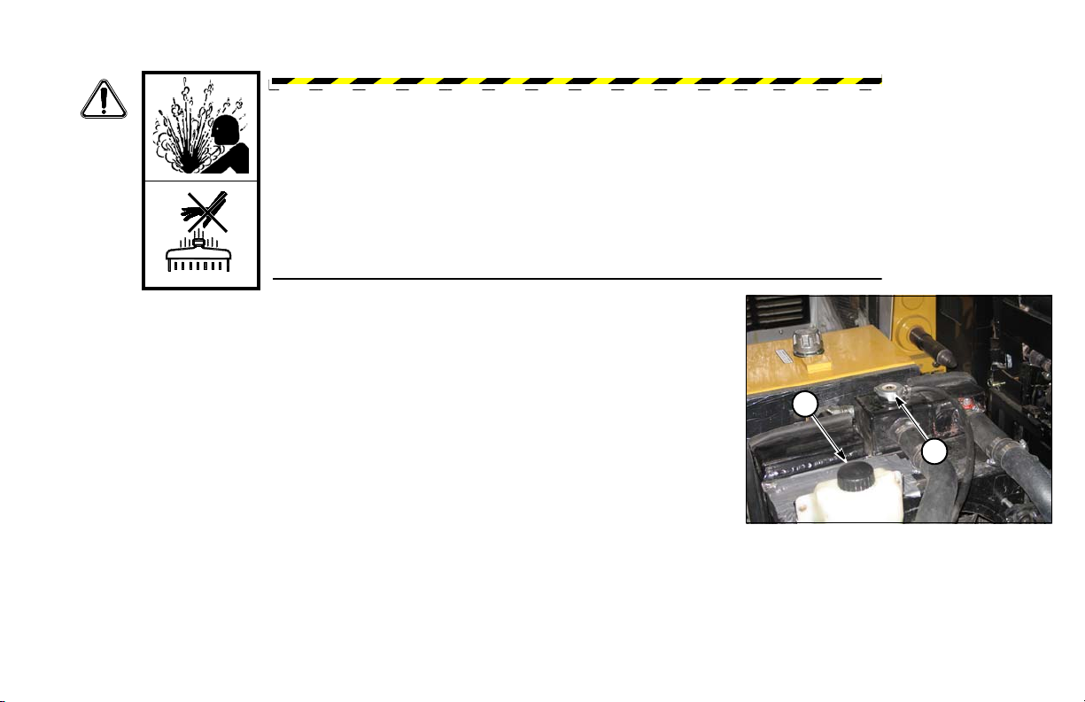
Coolant Level - Check
1
2
WAR NING : Hot fluid under pressure can scald.
Allow engine to cool before opening radiator cap.
Fill to within 1/2˝ (13 mm) of bottom of fill pipe with a low-silicate (ethylene glycol)
antifreeze and clean water mixture.
NOTICE: Never add pure antifreeze to a cooling system. We recommend using a 50/50
mixture. Never use high-silicate antifreeze or antifreeze that is higher than a 60/40
mixture.
(1) Fill Cap
(2) Overflow Bottle
D20x22 Series II HDD Maintenance 10 Service Hours or Daily 20-3
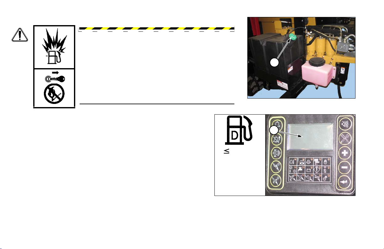
Fuel Tank - Fill
1
15 mg/kg
S
2
WAR NING : Fuel and fumes can explode and burn.
Shut off engine before refueling. No flame. No smoking.
Fill fuel tank at the end of each day to reduce condensation. Do not fill
to the very top; leave room for expansion.
Fuel Capacity: 25 gal (95 L)
Refer to the Engine Operation Manual for engine service requirements.
(1) Fill Cap
(2) Fuel Level (on display)
To meet government emission requirements use diesel fuel with a low or
ultra low sulfur content, less than 15 ppm or 0.0015% (15 mg/kg).
NOTICE: Use of higher content sulfur fuel will cause engine damage and
void engine warranty.
20-4 10 Service Hours or Daily D20x22 Series II HDD Maintenance
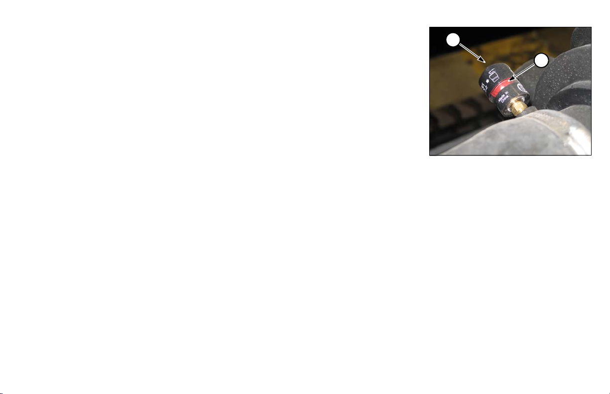
AIR CLEANER RESTRICTION INDICATOR - CHECK
1
2
When yellow indicator reaches the red area on indicator (1), replace air cleaner filter
element. Push button (2) to reset indicator.
• Do not remove element until the indicator shows it needs to be replaced.
• Do not wash or blow out element; it must be replaced.
NOTICE: The air restriction indicator will not function properly if:
• Element is damaged or not seated properly in housing.
•Air cleaner element body is damaged. If so, unfiltered air may be entering engine.
•Air transfer duct between air cleaner and engine is damaged or its clamps are
loose.
•Air duct between air cleaner and restriction indicator is damaged or pinched.
DRILL ROD CARE
Inspect drill rod before and during each use.
•Remove any rod from drill string with damaged or worn ends.
•Remove any bent rod from drill string.
•Use proper thread or profile gauge to check for damaged thread.
•After rods are coupled together, check for fluid leakage at the joint.
•Leaking drill rod joints indicate damaged shoulders, which will not torque properly.
•Check shoulders for dents, gouges, or high spots.
• Dress damaged shoulders with a file.
Do not exceed bend radius of the drill rod. Doing so will cause premature failure of the drill rod.
D20x22 Series II HDD Maintenance 10 Service Hours or Daily 20-5
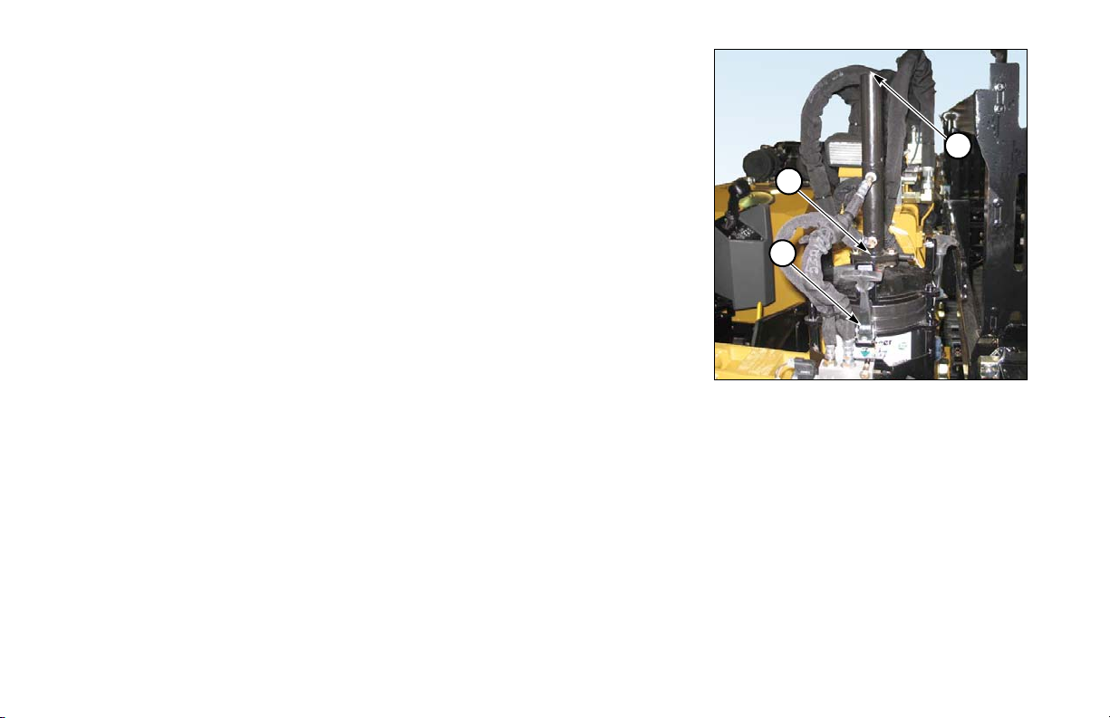
AUTO GREASER - ADJUST/CHECK/REFILL
3
1
2
Check the level of grease each day at start-up. Refill as needed.
•To refill, release latches (1) to lift pump and hoses and replace bucket.
•To fill and prime, use power greaser at fitting (2).
•To adjust amount of grease dispensed, remove plug (3) at top of tube with Allen
wrench to remove top cap and turn screw:
clockwise . . . . . . . . . . . . . . . . . . . . . . . . . . . . . . . . . . . . . . . . increase grease
counterclockwise. . . . . . . . . . . . . . . . . . . . . . . . . . . . . . . . . .decrease grease
20-6 10 Service Hours or Daily D20x22 Series II HDD Maintenance
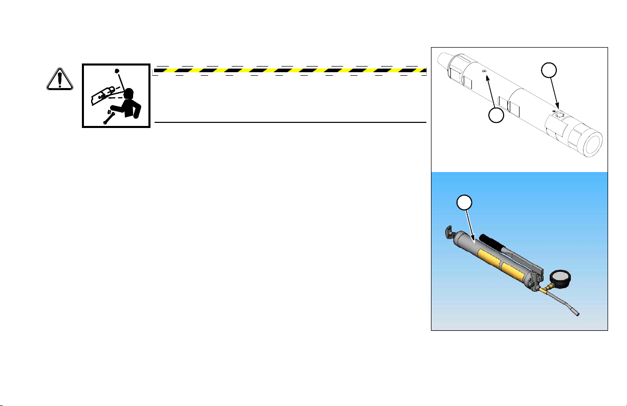
R.A.T.T. TOOL
2
1
3
Tool - Oil
WAR NING : Some residual pressure may remain in the
R.A.T.T. body. Use caution when removing any plugs. If
residual pressure is present in the tool body, it will be released.
Do not stand in front of any plugs when removing them.
Oil tool daily or after every bore. Use DEXRON III or MERCON automatic
transmission fluid.
Step 1: Elevate fill vent plug (1) end of tool at a minimum angle of 10°.
Step 2: Remove vent plug and fill cap (2).
Step 3: Use oil gun (3) provided to fill tool. The attached pressure gauge will read
Step 4: As soon as the ATF flows out of the vent hole, install plug (1).
Step 5: Continue to fill the tool until the gauge reads approximately 70 psi
D20x22 Series II HDD Maintenance 10 Service Hours or Daily 20-7
around 50 psi (3.5 bar).
(4.8 bar). Replace fill cap.

Rotation Sensor Phase - Verify
2
1
Verify Rotation Sensor Phase is calibrated correctly.
Step 1: Press Service Screen Key (1).
Step 2: Use Increase/Decrease Keys to scroll to “RCKCAL”.
Step 3: Move Rotation Handle out of NEUTRAL.
Display (2) should read a positive 85–90°.
Refer to “Rotation Sensor Phase - Adjust,” page 50-10.
VISES - INSPECT/CLEAN
Inspect vise dies and remove debris with a wire brush.
20-8 10 Service Hours or Daily D20x22 Series II HDD Maintenance
Section 25: Maintenance - 50 Service Hours or Weekly
1
FUEL/WATER SEPARATOR - DRAIN
Tier 4/Stage IIIB engine only
Refer to the Engine Operation Manual supplied with each machine for instructions.
WAR NING : Fuel and fumes can catch fire or explode,
resulting in serious burns or death.
Shut off engine before refueling. Never work around fuel
while smoking or near an open flame.
Drain fuel/water separator (1) weekly.
Do not spill fuel. Catch expelled fuel in an appropriate container.
ENGINE OIL AND FILTER - INITIAL CHANGE
Change engine oil and replace filter after the first 50 service hours, and then every 500 service hours.
Refer to “Engine Oil and Filter - Change,” page 40-3.
D20x22 Series II HDD Maintenance 50 Service Hours or Weekly 25-1
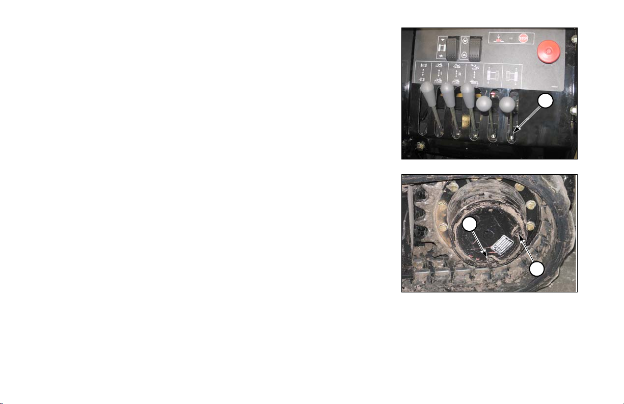
CONTROL LEVERS LINKAGE - OIL
1
1
2
(1) Control Levers Linkage
Apply a light coating of oil on linkage attachment points.
TRACK GEARBOX OIL LEVEL - CHECK
Oil requirements are listed in the Specifications section “Lubricants.”
Refer to page 65-1.
Check oil level with plug at 3:00 or 9:00 position. Fill to check plug level.
(1) Fill/Check Plug
(2) Drain Plug
25-2 50 Service Hours or Weekly D20x22 Series II HDD Maintenance
 Loading...