

Vermason 225208 Installation, Operation And Maintenance Manual
SINGLE CONTINUOUS MONITOR FOR
WRIST STRAP AND BENCHMAT
Installation, Operation and Maintenance
UNIT C, 4TH DIMENSION, FOURTH AVENUE, LETCHWORTH, HERTS, SG6 2TD UK
Phone: 0044 (0) 1462 672005, Fax: 0044 (0) 1462 670440 • e-mail: Service@Vermason.co.uk, Internet: Vermason.co.uk
TB-7562 December 2008 Page 1 of 2 © 2008 Vermason
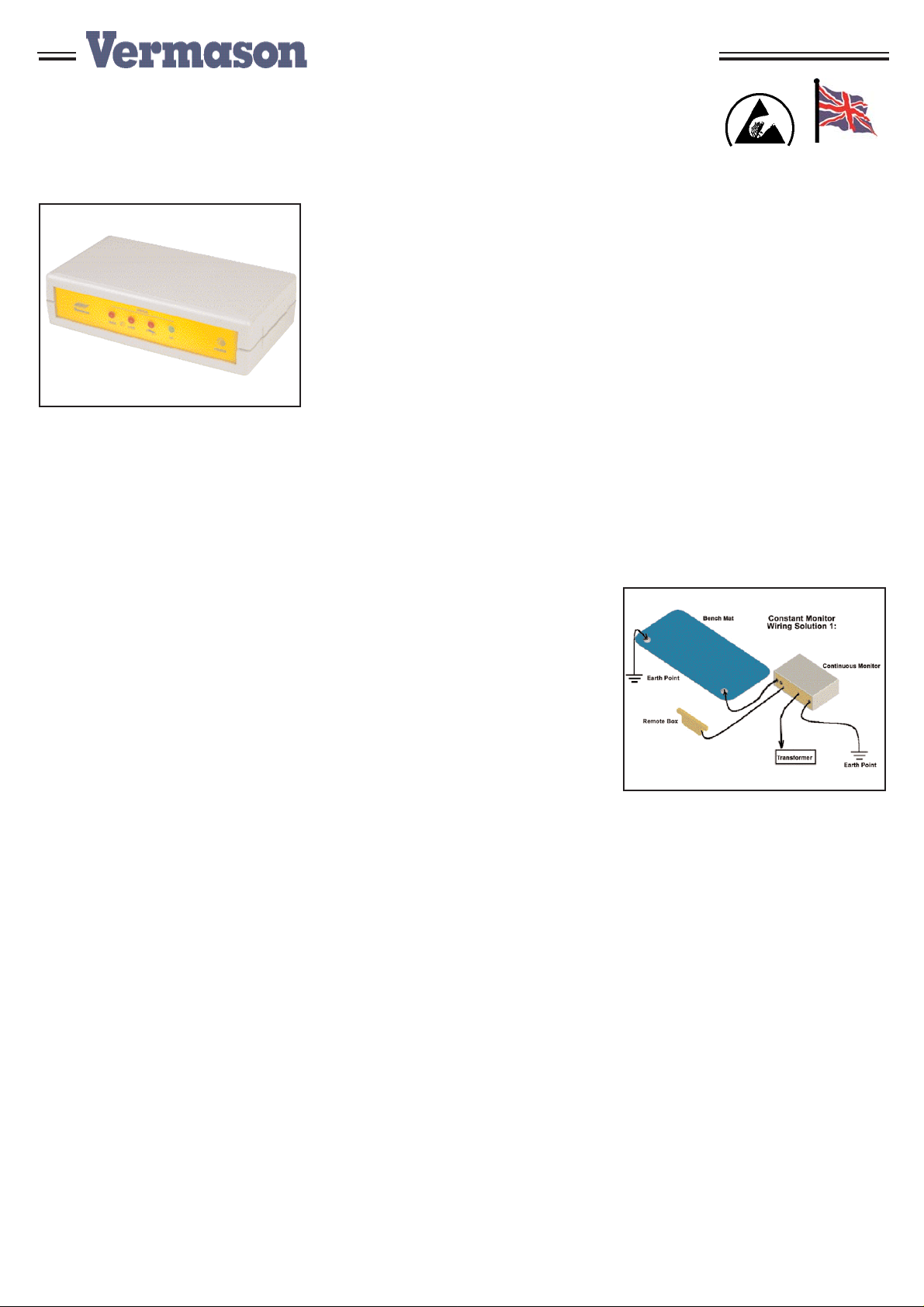
Figure 1. 225208 Single Continuous
Monitor.
Description
The 225208 continuous monitoring
system provides constant monitoring
of personnel and work surface
grounding. It operates using a
current loop and dual wrist strap
system. It uses a low-test voltage
and current which makes it suitable
for use with most ESD sensitive
items. The unit is unaffected by
capacitance variations associated
with personnel and environmental
conditions. It is suitable for use in
some clean rooms. The resistance
thresholds are set to meet the
requirements of EN 61340-5-1 but
they can be altered if required.
Leading companies use continuous
monitors as a cost effective
component in satisfying some of the
audit and check requirements of EN
61340-5-1. Wrist strap testing
“Where continuous monitoring is
used, no additional testing is
required.” (EN 61340-1, per A.5.2)
“The wrist band will normally be worn
for several hours at a time so it
needs to be comfortable while
making good contact with the skin. It
is a good idea to check the wrist
strap every time it is applied.
Constant on line monitors can be
used to that any breaks will be
immediately found.” (EN 61340-5-2
section 5.2.7)
Inspection
Remove the test unit from the carton
and inspect for shipping damages.
Each 225208 unit should include the
following:
1 Single Continuous monitoring
unit, item #225207
1 Dual fabric wrist band
1 Dual cord for dual wrist band
1 Remote connecting box (with a
monitored socket and guest
connection) complete with
mounting screws
2 mat grounding cords, 2.5m
long, 10 mm socket / 4mm
banana plug
1 monitor grounding cord,
2.5m long, 4mm plug/ring
terminal
1 Power supply UK
1 Screws, adhesive hook and loop
straps for mounting monitor
1 Washers, studs, screws for
connecting to bench top
Installation
1. Determine the mounting location of
the monitor (225207) and remote
boxes (225204). The monitor can
easily be mounted on top of the
work surface or underneath a shelf
using double-sided adhesive hook
and loop straps, or the supplied
screws. The front panel should be
readily visible to the operators.
The remote box should be
mounted in an easily accessible
position, as the operator has to be
connected to this box.
2. Wire the remote boxes to the
monitor by connecting the stereo
jack plug to the jack socket
mounted on the back panel of the
monitor. This cord provides a path
to ground for the monitored wrist
strap socket and the guest socket,
as well as the monitoring signal.
The picture on the right shows
how to connect the remote boxes
to the back panel of the
instrument.
3. Mount two 10 mm press-studs on
the work surface about 5 cm
apart. Two types of press-studs
are included with the kit; choose
the most convenient one for your
surface. If using hard laminate
ensure that both press-studs are
making connection with the
conductive layer. It is generally
good to use the supplied rubber
washer to ensure optimum
connection, whatever the type of
surface. Place it under the stud
on the surface.
4. It is possible to connect the mats
in two different ways:
Solution 1: connect one stud to
the earth and the other to the
monitor.
Note: The earth loop is monitored
with this method of wiring, if the
earth cord is disconnected, the
instrument will alarm
Figure 2. 225208 Wiring Solution 1.
Solution 2: Connect both
studs on the mat to the
monitor using two 230385
cords.
Note: The earth loop is not
monitored with this method of
wiring. If the earth cord is
disconnected, the instrument will
not alarm. However, the two mat
testing circuits are fully
independent.
Use only this wiring solution if the
bench top resistance is very high
and the standard connection
method does not provide
satisfactory results. With this
method, the earth cord must be
hard-wired and tested regularly.
TECHNICAL BULLETIN TB-7562
Made in Britain

Solution 2 ensures correct
threshold monitoring of the mat's
resistance. Use Solution 2 only if
Solution 1 does not provide
satisfactory results. However, the
advantage of solution 1 is that the
mat and the instrument ground
connections are monitored which
is more meaningful than the mat
resistance.
5. Connect the system to earth
facility using a cord inserted into
the 4mm plug socket
6. Plug the DC power supply plug
(224700) into the power jack in the
rear of the unit. Route the wire
from the supply to a nearby mains
socket and plug the power supply
into the socket.
Unit Operation
Install the operator wristband and
ground cord (225200 and 225202).
The right-angled plug inserts into the
socket on the yellow remote box. The
wrist strap is monitored as soon as
the cord is connected to the remote
box socket.
Note: The remote box is fitted with
three sockets, a jack stereo socket
and two 4mm plug socket. The latter
are for guest use, and are not
monitored.
The front panel
The LED located in the centre of the
unit indicates the status of the
workstation. On the far right of the
unit is an orange LED indicating that
the unit is powered.
The workstation status is indicated
via 4 LED and a buzzer. The buzzer
and the two red LED labeled "Low"
and "High" indicate if the wrist strap
resistance, when worn, is lower than
0.75MΩ or higher than 35MΩ .
These LED should not come on
when the resistance of the wrist strap
is within these limits. Assuming
Solution 1 has been chosen, the LED
labeled "Mat" will turn red when the
resistance to ground of the work
surface is higher than 100MΩ .
Limited Warranty
Vermason expressly warrants that for a period
of one (1) year from the date of purchase,
Vermason
Single Continuous Monitor For Wrist
Strap and Benchmats
will be free of defects in
material (parts) and workmanship (labour).
Within the warranty period, a unit will be
tested, repaired or replaced at Vermason’s
option, free of charge. Call Customer Service
at
0044 (0) 1462 672005
for a Return Material
Authorisation (RMA) and for proper shipping
instructions and address. Any unit under
warranty should be shipped prepaid to the
Vermason factory. You should include a copy
of your original packing slip, invoice, or other
proof of purchase date. Warranty repairs will
take approximately two weeks.
If your unit is out of warranty, Vermason will
quote repair charges necessary to bring your
unit to factory standards. Call Customer
Service at
0044 (0) 1462 672005
for a Return
Material Authorisation (RMA) and proper
shipping instructions and address.
Warranty Exclusions
THE FOREGOING EXPRESS WARRANTY IS
MADE IN LIEU OF ALL OTHER PRODUCT
WARRANTIES, EXPRESSED AND IMPLIED,
INCLUDING MERCHANTABILITYAND
FITNESS FOR APARTICULAR PURPOSE
WHICH ARE SPECIFICALLY DISCLAIMED.
The express warranty will not apply to defects
or damage due to accidents, neglect, misuse,
alterations, operator error, or failure to properly
maintain, clean or repair products.
Limit of liability
In no event will Vermason or any seller be
responsible or liable for any injury, loss or
damage, direct or consequential, arising out of
the use of or the inability to use the product.
Before using, users shall determine the
suitability of the product for their intended use,
and users assume all risk and liability
whatsoever in connection therewith.
Should the mat resistance be below
this limit, and the worn wrist strap
resistance be between 0.75 and
35MΩ limits, the green "OK" LED
should turn on and the buzzer will
remain silent.
Parking a station
When an operator has to leave the
work area, his wrist strap monitor
should be parked by unplugging his
wrist strap ground cord from the
remote box. In this situation the
green "OK" LED will not illuminate
and the buzzer will remain silent.
Certification
Depending upon the requirements of
a facility, periodic verification of the
monitoring unit may be performed
using a calibrated decade box
Vermason product code 223000.
The calibration procedure is
described in the Instructions for Use
of this decade box.
Specifications
Test voltage: Max 5 Volts DC
Test current: Max 5µA
Resistance settings
Lower limit: 0.7-0.8MΩ
adjustable from 0.5
to 2MΩ
Upper limit: 34-36MΩ adjustable
from 25 to 50MΩ
Accuracy, mat test:
± 10% (both mat connectors wired to
the monitor, wiring solution 1).
Calibration, mat test:
90-100MΩ (fully adjustable from 25
to 110MΩ )
Station status indication via 4 LED
+power-on LED
Station parking facility (unplug wrist
strap from remote box)
UNIT C, 4TH DIMENSION, FOURTH AVENUE, LETCHWORTH, HERTS, SG6 2TD UK
Phone: 0044 (0) 1462 672005, Fax: 0044 (0) 1462 670440 • e-mail: Service@Vermason.co.uk, Internet: Vermason.co.uk
TB-7562 Page 2 of 2
 Loading...