

Vermason 222696 Operation Instructions Manual
TECHNICAL BULLETIN TB-7573
Limit Comparator
Operation Instructions
Figure 1. Vermason 222696 Limit Comparator
Description
Frequency of recalibration should be based on the critical
nature of those ESD sensitive items handled and the risk
of failure for the ESD protective equipment and materials.
In general, Vermason recommends that calibration be
performed annually.
Use the Vermason 222696 Limit Comparator to perform
periodic testing (once every 6-12 months) of the Combo
Tester X3. The Limit Comparator can be used on the shop
floor within a few minutes virtually eliminating downtime,
verifying that the tester is operating within tolerances.
The Vermason 222696 Limit Comparator is to be used with
the following items:
Item Description
222550 Combo Tester X3
222551 Combo Tester X3 with Stand
222553 Combo Tester X3 with 10mm Adaptor
222554 Combo Tester X3 with Stand and 10mm
Adaptor
Made in the
United States of America
Packaging
1
Limit Comparator
2 Test Leads with Banana Plug Terminals
1 Certificate of Calibration
Tester Configuration
The resistance limits for footwear and wrist strap tests are
controlled by the DIP switches located on the left side of the
tester. Use the following tables for the DIP switch settings
and their corresponding test values.
Left Side View
Figure 2. Locating the DIP switch on the Combo Tester
X3
FOOTWEAR RESISTANCE
DIP switches 1 and 2 control the HIGH test limit.
Switch 1 Switch 2 HIGH Limit Resistance
ON ON 10 Megohms (1 x 10
OFF OFF 35 Megohms (3.5 x 10
ON OFF 100 Megohms (1 x 10
OFF ON 1 Gigohm (1 x 10
DIP switches 3 and 4 control the LOW test limit.
Switch 3 Switch 4 LOW Limit Resistance
ON OFF 100 Kilohms (1 x 10
OFF ON 750 Kilohms (7.5 x 10
default setting
NOTE: At 1 Gigohm high limit resistance, a dirty foot
plate could result in a false pass. Be sure to keep the
foot plate clean particularly when using this setting.
This setting is not suitable for relative humidity greater
than 50%.
7
)
7
)
8
)
9
)
5
)
5
)
Phone: 0044 (0) 1462 672005, Fax: 0044 (0) 1462 670440 • E-mail: Service@Vermason.co.uk, Internet: Vermason.co.uk
TB-7573 Page 1 of 3
October 2013
UNIT C, 4TH DIMENSION, FOURTH AVENUE, LETCHWORTH, HERTS, SG6 2TD UK
© 2013 Vermason
WRIST STRAP RESISTANCE
DIP switches 5 and 6 control the HIGH test limit.
Switch 5 Switch 6 HIGH Limit Resistance
OFF OFF wrist strap test disabled
ON ON 10 Megohms (1 x 10
ON OFF 35 Megohms (3.5 x 10
7
)
7
)
default setting
DIP switch 5 must be ON (default setting) for the wrist
strap test to be active. The wrist strap test will be
disabled if DIP switch 5 is set to OFF.
The LOW limit for the wrist strap test is set to 750
Kilohms and cannot be modified by the user.
5. Select the appropriate PASS HIGH setting on the Limit
Comparator and repeat the test. The tester should
indicate a PASS condition for both feet.
6. Select the appropriate FAIL HIGH setting on the Limit
Comparator and repeat the test. The tester should
indicate a FAIL HIGH condition for both feet.
NOTE: The Combo Tester X3 does not feature any
adjustable parts for calibration. The tester must be returned
to the manufacturer for re-calibration should it fail any
calibration tests with the Limit Comparator.
Specifications
Dimensions:
3.8" L x 2.4" W x .9" H
(9.7 cm x 6.1 cm x 2.3 cm)
Operation
Testing the Wrist Strap Circuit
1. Plug the two included test leads into each yellow banana
jack located at the top of the Limit Comparator.
2. Connect one of the test leads from the Limit Comparator
to the “SINGLE-WIRE” jack located on the face of the
tester. Connect the other lead from the Limit Comparator
to the ground jack located on the bottom of the tester.
3. Select “750K LOW” with the Limit Comparator’s rotary
switch.
4. Touch and hold the test plate of the tester until the test
is completed. The tester should indicate a wrist strap
FAIL LOW condition.
5. Select “750K PASS” on the Limit Comparator and repeat
the test. The tester should indicate a wrist strap PASS
condition.
6. Select either the “10M PASS” or “35M PASS” setting,
whichever one is appropriate, on the Limit Comparator
and repeat the test. The tester should indicate a wrist
strap PASS condition.
7. Select either the “10M HIGH” or “35M HIGH” setting,
whichever one is appropriate, on the Limit Comparator
and repeat the test. The tester should indicate a wrist
strap FAIL HIGH condition.
Testing the Footwear Circuit
1. Insert the Limit Comparator’s stereo plug into the jack
labeled “FOOT PLATE” on the bottom of the tester.
2. Select the appropriate FAIL LOW setting on the Limit
Comparator.
Weight:
.2 lbs
(.1 kg)
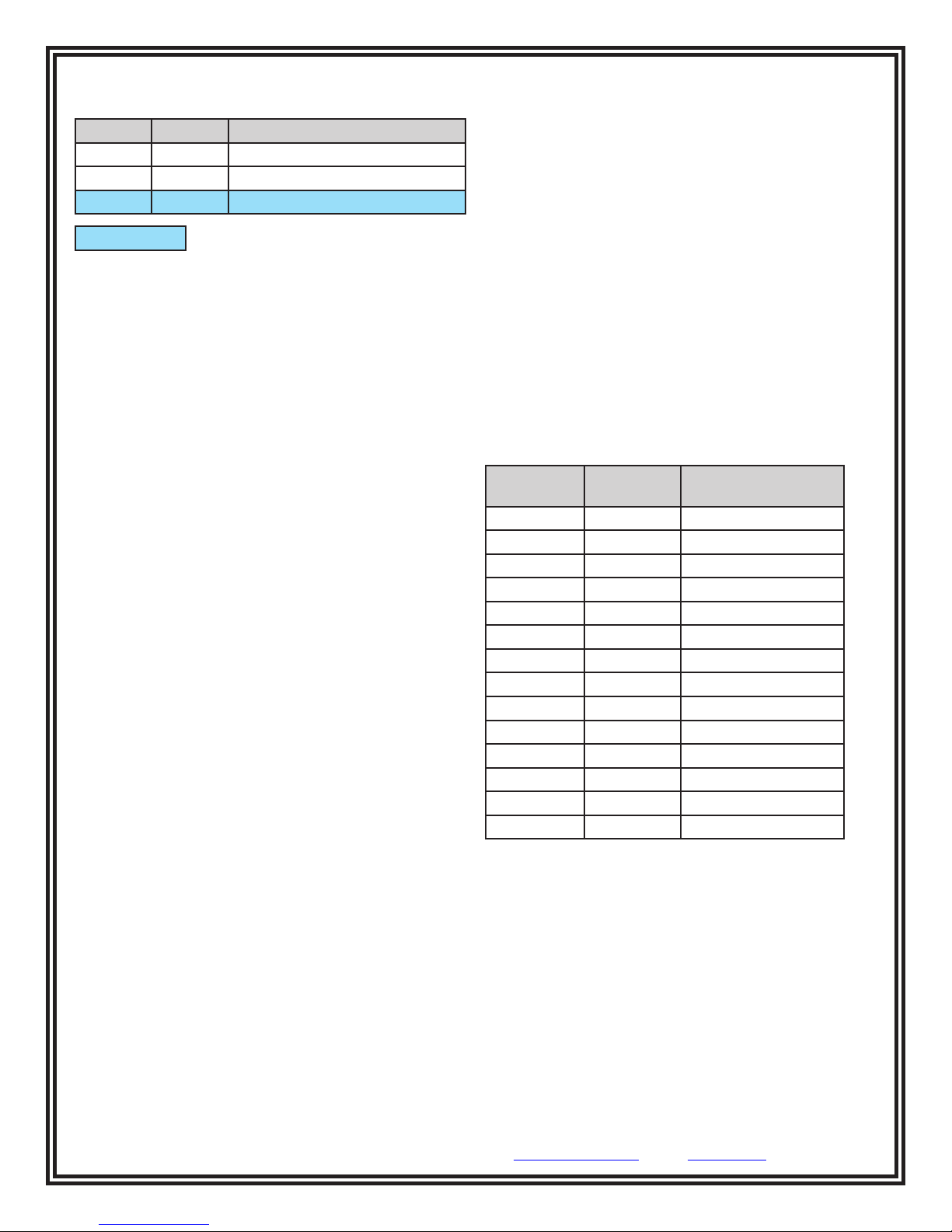
Resistance Values:
Setting Nominal
Resistance
% Tolerance of
Nominal Resistance
100K LOW 90K ±2%
100K PASS 110K ±2%
750K LOW 675K ±2%
750K PASS 825K ±2%
1M LOW 909K ±2%
1M PASS 1.10M ±2%
10M PASS 9.09M ±2%
10M HIGH 11.09M ±2%
35M PASS 31.09M ±2%
35M HIGH 37.89M ±2%
100M PASS 90.9M ±5%
100M HIGH 112.9M ±5%
1G PASS 812.9M ±5%
1G HIGH 1.213G ±5%
These resistance values may be verified using a digital
voltmeter by setting it to read Ohms (Ω). Connect your
voltmeter’s test leads into each of the Limit Comparator’s
yellow banana jacks. If any value is out of specification, the
Limit Comparator must be returned to the manufacturer for
repair.
3. Touch and hold the test plate of the tester until the test
is completed. The tester should indicate a FAIL LOW
condition for both feet.
4. Select the appropriate PASS LOW setting on the Limit
Comparator and repeat the test. The tester should
indicate a PASS condition for both feet.
UNIT C, 4TH DIMENSION, FOURTH AVENUE, LETCHWORTH, HERTS, SG6 2TD UK
Phone: 0044 (0) 1462 672005, Fax: 0044 (0) 1462 670440 • E-mail: Service@Vermason.co.uk, Internet: Vermason.co.uk
TB-7573 Page 2 of 3
© 2013 Vermason
 Loading...