

Vermason 222693 Installation And Operating Instructions Manual
Limit Comparator for Testers
Installation and Operating Instructions
UNIT C, 4TH DIMENSION, FOURTH AVENUE, LETCHWORTH, HERTS, SG6 2TD UK
Phone: 0044 (0) 1462 672005, Fax: 0044 (0) 1462 670440 • e-mail: Service@Vermason.co.uk, Internet: Vermason.co.uk
TB-7541 December 2008 Page 1 of 3 © 2008 Vermason
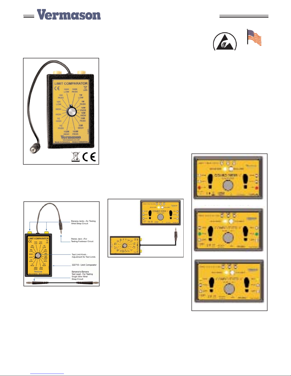
Figure 1. Item 222693 Limit
Comparator
Description
Figure 2 shows the components of
the limit comparator.
Figure 2. Components of item
222693
Installation
Remove the Limit Comparator from
the carton and inspect for shipping
damage. Included with the unit are:
• 1 Limit Comparator
• 2 Test Leads, Banana to Banana
• 1 NIST Certificate of Calibration
Operation
Testing Footwear Circuit, refer to
figure 3.
To complete the footwear test, you
will need to test the low and high
limits. Refer to the dip setting on the
left side of the testers for footwear
test ranges. Manufacturer’s
suggested default test range is 1Meg
low and 35Meg high for the US and
Europe.
Do not power down tester, remove
stereo cable from bottom right jack of
tester labeled "FOOTPLATE" and
connect the stereo lead from model
222693 to the jack labeled
"FOOTPLATE".
Figure 3. Footwear test setup
Testing Low Circuit - If the tester's
low range is set to 1Meg. Set the
knob on model 222693 to the "1M
LOW" position. Push the metal
button down on the tester and you
should get a red LED for the left and
right foot. Disregard the test result for
the wrist strap if the wrist strap circuit
is on.
Set the knob on model 222693 to
"1M Pass", push the metal button on
the tester and you should get a
green LED for the left and right of the
foot.
Testing High Circuit - If the tester's
high range is 35Meg. Set the knob
on model 222693 to "35M PASS",
push the metal button on the tester
and you should get a green LED for
the left and right feet. Set the knob
on model 222693 to "35M HIGH",
push the metal button on the tester
and you should get a yellow LED for
both the left and right feet. If the limit
is set to 1Gig on the tester, test at
1Gig on model 222693, same for
10Meg and 100Meg.
Figure 4. Footwear test results
TECHNICAL BULLETIN TB-7541
Made in America
Footwear Low Fail
Footwear Low and High Pass
Footwear High Fail
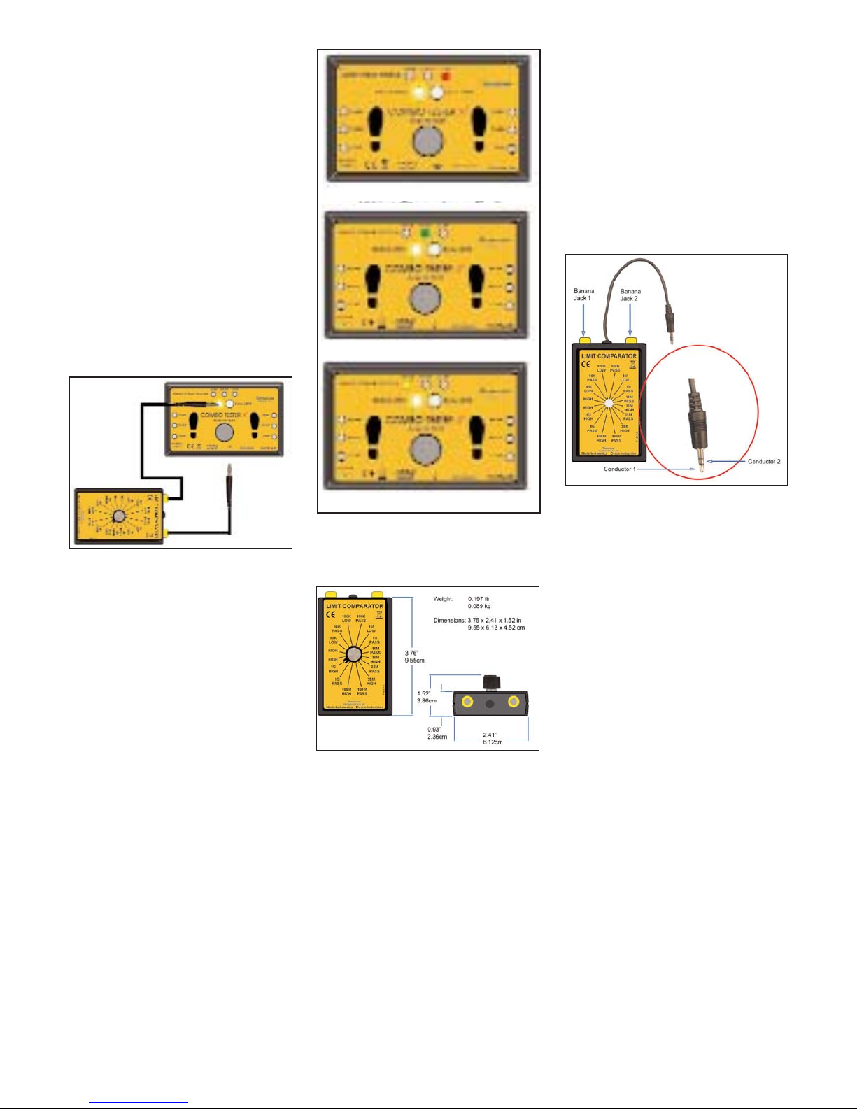
Testing Wrist Strap Circuit, refer to
figure 5.
To complete the wrist strap test, you
will need to test the low and high
limits. Refer to the dip setting on the
left side of the testers for wrist strap
test ranges. Manufacturer’s
suggested default test range is 1Meg
low and 10Meg high for the US and
1Meg to 35Meg for Europe.
Do not power down the tester. Using
the 2 banana leads included with
model 222693. Attach 1 of the
banana leads to the right side
banana jack on model 222693 and
connect the other end to the ground
symbol jack on the tester. Connect
the last banana jack to the left
banana jack of model 222693 and
the other end to the "SINGLE WIRE" banana jack
Figure 5. Wrist strap test setup
Testing Low Circuit - If the tester's
low range is set to 1Meg. Set the
knob on model 222693 to the "1M
LOW" position. Push the metal button
down on the tester and you should
get a red LED for the Wrist strap.
Disregard the test result for the
footwear. Set the knob on model
50401 to "1M Pass", push the metal
button on the tester and you should
get a green LED for the wrist strap.
Testing High Circuit - If the tester's
high range is 10Meg. Set the knob on
model 222693 to "10M PASS" and
push the metal button on the tester
and you should get a green LED for
the wrist strap. Set the knob on
model 222693 to "10M HIGH" and
push the metal button on the tester
and you should get a yellow LED for
the wrist strap. If the limit is set to
35Meg on the tester, then test at
35Meg on model 222693.
Figure 6. Wrist Strap test results
Specifications and
Dimensions
Figure 7. Dimensions of the 222693
The 22693 limit comparator will
calibrate the following testers:
222720 - SmartLog X3 w/Dual Foot
Plate, Keypad, & Barcode Reader,
120V
222700 - Dual Independent Footwear
and Wrist Strap Tester
222690 - Dual Independent Footwear
Tester
Calibration
There are no user adjustments on
model 222693. Each value is a fixed
resistor load, any model 222693 that
falls out of specification will need to
be sent to factory for repair. Using a
DVM (digital voltage meter) set the
meter to read ohms. The limit that
the knob is set on can be measured
using the DVM connected between
Banana 1 to Banana 2 and
connected between Conductor 1 and
Conductor 2. Refer to figure 8.
Figure 8. Test points
UNIT C, 4TH DIMENSION, FOURTH AVENUE, LETCHWORTH, HERTS, SG6 2TD UK
Phone: 0044 (0) 1462 672005, Fax: 0044 (0) 1462 670440 • e-mail: Service@Vermason.co.uk, Internet: Vermason.co.uk
TB-7541 Page 2 of 3 © 2008 Vermason
Wrist Strap Low Fail
Wrist Strap Low and High Pass
Wrist Strap High Fail
 Loading...