

TECHNICAL BULLETIN TB-7591
Low Resistance Tester
Operation and Maintenance
ANSI/ESD S6.1 – Grounding
“6.4.1 The resistance of the conductor from the groundable
point ground of any ESD technical element (e.g. worksurface,
floor, chair, wrist strap, etc.) to the common point ground or
common connection point shall not be greater than 1 ohm.
Where a resistor is used in the grounding conductor, the total
resistance shall include the value of the resistor.
6.4.2 The resistance of the conductor from the common point
ground to the AC equipment ground shall not be greater than
1 ohm.”
Packaging
1 Low Resistance Tester
1
1 Threaded Needle Point
1 Alligator Clip
1 Banana Plug / 10mm Snap Adapter
1 Certificate of Calibration
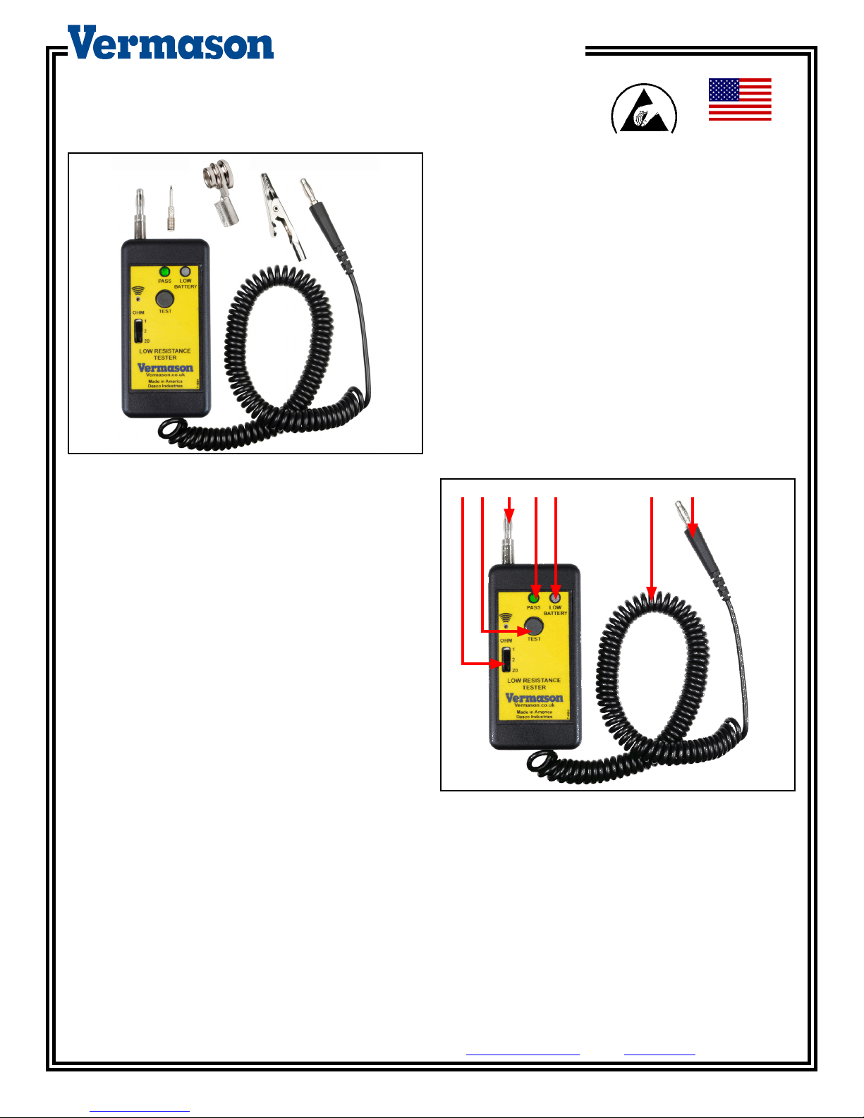
Figure 1. Vermason 222644 Low Resistance Tester
Description
Vermason’s Low Resistance Tester is designed to measure
resistance of grounding paths of banana jacks, common
ground points, earth bonding points and other equipment.
Selectable Test Ranges: <1 ohm, <2 ohms and <20 ohms
allow the operator to test grounding conductors per ANSI/
ESD S6.1 – Grounding and ESD TR20.20. The Tester is
equipped with pass/fail (go/no go) audio and visual indicators
that activate to confirm that the grounding conductor being
tested meets the test range. The low battery indicator lets
the operator know when battery needs to be replaced.
Features and Components
Threaded Banana Plug
A B C D E G
F
Made in the
United States of America
ESD Handbook ESD TR20.20 section 5.5.2.2 Electrical
Hand Tools
“All electrical tools and equipment used to process ESD
sensitive devices require the three prong, grounded-type AC
plug. The metal portions of the tool that touch the device
should have a low resistance (<2 ohms) to the equipment
ground terminal on the plug. In some cases, the user
may wish to verify that the metal portions of the tool have
acceptable voltage levels and leakage current. The tester
defined in ESD STM13.1 provides a means of checking
soldering iron tips while being used. Although the document
was written to make measurements on soldering and
desoldering equipment, the measurement techniques can be
used for other electrical hand tools. The working part of AC
powered tools should be capable of providing a conductive
path to ground. New powered hand tools such as soldering
irons typically should have a tip to ground resistance of less
than 1.0 ohm.
NOTE: This resistance may increase with use but should be
less than 20.0 ohms for verification purposes.”
Phone: 0044 (0) 1462 672005, Fax: 0044 (0) 1462 670440 • E-mail: Service@Vermason.co.uk, Internet: Vermason.co.uk
TB-7591 Page 1 of 4
September 2013
UNIT C, 4TH DIMENSION, FOURTH AVENUE, LETCHWORTH, HERTS, SG6 2TD UK
Figure 2. Low Resistance Tester features and
components
A. Selectable Test Ranges: Select the appropriate range
for required test <1 OHM, <2 OHMs, and <20 OHMs.
B. Test Button: Press and hold button to activate the tester.
C. Threaded Banana Plug/Needle Point: Standard Kit
includes a banana plug and needle point adapter.
D. Audio and Visual Test Indicators: LED and buzzer Pass
result.
© 2013 Vermason
E. Low Battery LED: LED illuminates when the battery
needs to be replaced.
F. 6 Foot Coiled Cord: Insulation black colour PVC.
G. Banana Plug: Industrial Standard .175" (4.4 mm) Banana
Plug, fits banana jack ≥ .157".
Operation
USING THE TESTER
1. Use the slide switch to select a test range.
2. Connect the coiled cord’s banana plug end to known
ground. Use adapters where needed. NOTE: The
Vermason Low Resistance Tester may be used with
an outlet polarity checker such as the Vermason 222606
or 222607 to determine a known ground.
3. Connect or touch the tester end to a banana jack,
common ground point, earth bonding point or other
equipment that is being tested for resistance to ground.
4. Press and hold the test button.
5. An audio and visual indication will activate for a PASS
condition.
6. A FAIL condition is indicated when the buzzer does not
sound and the PASS LED does not illuminate.
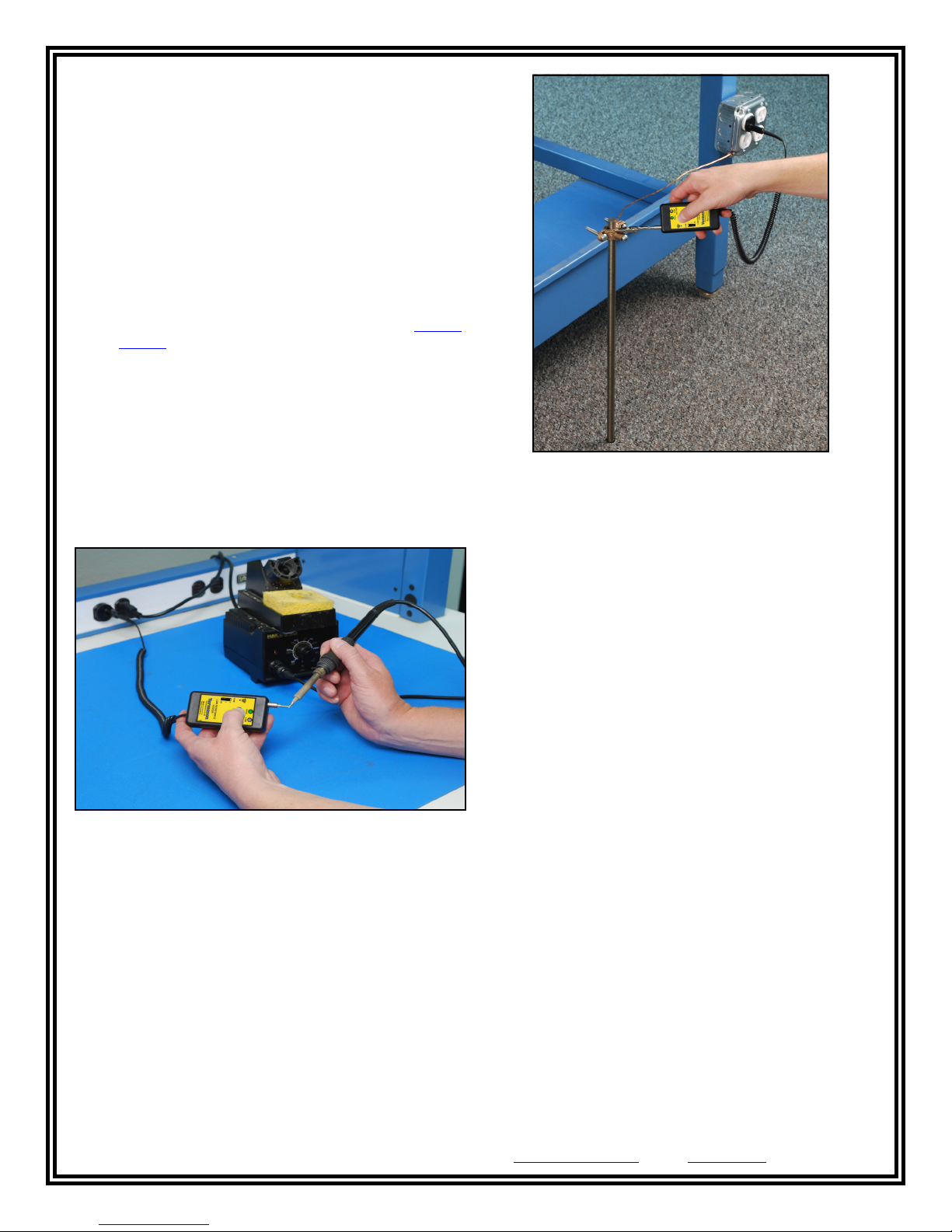
Figure 3. Testing a soldering iron with the 222644 tester
Figure 4. Testing functional auxiliary ground with the
222644 tester
Example of Test Range Uses
<1 OHM Range
- ESD Technical element Grounding Conductors:
Banana Jacks, Common Ground Points, Earth Bonding
Points, Grounding Blocks, Mat Ground Cords
ANSI/ESD S6.1 Grounding, sections 6.4 Technical
Elements, 6.4.1, 6.4.2 and 6.4.3
- New AC Powered Hand Tools
ESD Handbook ESD TR20.20 section 5.5.2.2 Electrical
Hand Tools
<2 OHM
- Soldering Irons
ESD Handbook ESD TR20.20 section 5.5.2.2 Electrical
Hand Tools
- Other AC Powered Hand Tools
ESD Handbook ESD TR20.20 section 5.5.2.2 Electrical
Hand Tools
<20 OHM
- Soldering iron compliance verification
ESD Handbook ESD TR20.20 section 5.5.2.2 Electrical
Hand Tools
- Functional auxiliary grounds (ground rods)
ANSI/ESD S20.20*
Phone: 0044 (0) 1462 672005, Fax: 0044 (0) 1462 670440 • E-mail: Service@Vermason.co.uk, Internet: Vermason.co.uk
UNIT C, 4TH DIMENSION, FOURTH AVENUE, LETCHWORTH, HERTS, SG6 2TD UK
TB-7591 Page 2 of 4
* ANSI/ESD S20.20 requires <25 ohms from the Auxiliary
Ground to the Equipment Grounding Conductor. Vermason’s
Low Resistance Tester only tests to <20 ohms. In cases of a
no pass result with the Low Resistance Tester when testing
an Auxiliary Functional Ground, an Ohmmeter should used to
determine the actual resistance from the Auxiliary Functional
Ground to Protective Earth Ground
© 2013 Vermason

Calibration
The Low Resistance Tester is calibrated to standards
traceable to NIST. Frequency of recalibratrion should be
based on the critical nature of those ESD sensitive items
handled and the risk of failure for the ESD protective
equipment and materials. In general, we recommend that
calibration be performed annually.
Calibration is performed by placing various resistors between
the probe tip and the lead wire.
1. Attach the alligator clip to the lead wire.
2. Set the Low Resistance Tester to the 1 ohm test setting.
3. Attach the lead of a 1 ohm resistor to the alligator clip.
4. Firmly place the tester’s probe tip on the opposite resistor
lead.
5. Press and hold the test button. The PASS LED should
illuminate.
6. Repeat the procedure with a 1.2 ohm resistor. The PASS
LED should not illuminate.
7. Repeat this process with the ranges listed in the table
below. If the unit fails calibration, check and replace the
battery.
Figure 6. Removing the back cover
3. Remove and turn over the circuit board.
4. Locate and replace the battery (3 Volt; Model CR2032).
First, place
battery under
prongs
Test Range Setting PASS FAIL
1 ohm 0 to 1 ohm ≥ 1.2 ohms
2 ohms 0 to 2 ohms ≥ 2.2 ohms
20 ohms 0 to 20 ohms ≥ 22 ohms
Maintenance
BATTERY REPLACEMENT
1. Properly ground yourself using a wrist strap.
2. Remove the 2 screws located at the back of the tester.
Next, press here to snap
battery in place
Figure 7. Replacing the battery
5. Re-assemble the tester.
Specifications
Output Voltage: 2.5 volts DC @ 10mA
Dimensions: 12 cm x 4.5 cm x 2 cm
Operating Temperature: 0° to 40°C
Figure 5. Locating the enclosure screws
UNIT C, 4TH DIMENSION, FOURTH AVENUE, LETCHWORTH, HERTS, SG6 2TD UK
Phone: 0044 (0) 1462 672005, Fax: 0044 (0) 1462 670440 • E-mail: Service@Vermason.co.uk, Internet: Vermason.co.uk
TB-7591 Page 3 of 4
© 2013 Vermason

Limited Warranty
Vermason expressly warrants that for a period of one (1) year from the date of purchase, Vermason
material (parts) and workmanship (labour). Within the warranty period, a unit will be tested, repaired or replaced at Vermason’s option, free of charge. Call
Customer Service at
warranty should be shipped prepaid to the Vermason factory. You should include a copy of your original packing slip, invoice, or other proof of purchase
date. Warranty repairs will take approximately two weeks.
If your unit is out of warranty, Vermason will quote repair charges necessary to bring your unit to factory standards. Call Customer Service at
1462 672005
0044 (0) 1462 672005
for a Return Material Authorisation (RMA) and proper shipping instructions and address.
for a Return Material Authorisation (RMA) and for proper shipping instructions and address. Any unit under
ESD Low Resistance Testers
will be free of defects in
0044 (0)
Warranty Exclusions
THE FOREGOING EXPRESS WARRANTY IS MADE IN LIEU OF ALL OTHER PRODUCT WARRANTIES, EXPRESSED AND IMPLIED, INCLUDING
MERCHANTABILITY AND FITNESS FOR A PARTICULAR PURPOSE WHICH ARE SPECIFICALLY DISCLAIMED. The express warranty will not apply to
defects or damage due to accidents, neglect, misuse, alterations, operator error, or failure to properly maintain, clean or repair products.
Limit of liability
In no event will Vermason or any seller be responsible or liable for any injury, loss or damage, direct or consequential, arising out of the use of or the
inability to use the product. Before using, users shall determine the suitability of the product for their intended use, and users assume all risk and liability
whatsoever in connection therewith.
Phone: 0044 (0) 1462 672005, Fax: 0044 (0) 1462 670440 • E-mail: Service@Vermason.co.uk, Internet: Vermason.co.uk
UNIT C, 4TH DIMENSION, FOURTH AVENUE, LETCHWORTH, HERTS, SG6 2TD UK
TB-7591 Page 4 of 4
© 2013 Vermason
 Loading...