

Vermason TB-7588, 222642, 222643, 222633, 222634 Installation, Operation And Maintenance Manual
...
TECHNICAL BULLETIN TB-7588
Digital Surface Resistance Meter Kit
Installation, Operation and Maintenance
The Surface Resistance Meter Kit (or its Meter) is referenced
and designed to be used to make measurements in
accordance with the test procedures in:
• Working surfaces, storage racks, trolleys and seating IEC 61340-2-3
• Flooring - IEC 61340-4-1
• Garments - ANSI/ESD STM2.1 Garments
• Person/footwear / flooring system - IEC 61340-4-5
“A compliance verification plan shall be established to ensure
the Organization’s fulfilment of the technical requirements
of the plan. Process monitoring (measurements) shall be
conducted in accordance with a compliance verification
plan that identifies the technical requirements to be verified,
the measurement limits and the frequency at which those
verifications shall occur. The compliance verification plan
must document the test methods and equipment used for
Figure 1. Vermason Digital Surface Resistance Meter
Kit
Description
The Vermason 222642 Digital Surface Resistance Meter
Kit is an instrument designed to measure resistance
point-to-point (Rp-p) or surface to ground (Rg) in accordance
with EN 61340-5-1 Electrostatics and its test method IEC
61340-2-3.
Its test functions include:
• Resistance measurement accuracy of ±10%
(±20% for resistance values 1 x 10¹¹ ohms and greater)
• Resistance range of <1 x 10
• Under load voltages of 10 and 100 volts ±5%
• Electrification period of approximately 15 seconds
3
ohms to >1 x 10
12
ohms
process monitoring and measurements. If the organization
uses test methods that differ from the standards referenced
in this standard, the organization must be able to show that
the results achieved correlate with the referenced standards.
Compliance verification records shall be established and
maintained to provide evidence of conformity to the technical
requirements.
The test equipment selected shall be capable of making the
measurements defined in the compliance verification plan.”
(IEC 61340-5-1 Edition 1 2007-08 clause 5.2.3 Compliance
verification plan)
Reference Literature
In addition to those noted above:
EN 61340-5-1 Electrostatics and PD CLC/TR 61340-5-2 User
Guide Electrostatics
Made in the
United States of America
The Digital Surface Resistance Meter also measures ambient
temperature and relative humidity.
NOTE: Volume Resistance can be measured using one 2 kg
Electrode and a flat conductive metal plate (not included).
The Digital Surface Resistance Meter Kit and its accessories
are available in the following item numbers:
Item Description
222642 Digital Surface Resistance Meter Kit
222643 Digital Surface Resistance Meter
222002 Concentric Ring Probe
222003 Concentric Ring Probe Kit
222633 Shielded Test Leads
222634 2 kg Electrodes, 1 Pair
DESCO EUROPE - 2A DUNHAMS LANE, LETCHWORTH, HERTFORDSHIRE, SG6 1BE, UK
Phone: +44 (0) 1462 672005 • E-mail: Service@DescoEurope.com, Website: DescoEurope.com
TB-7588 Page 1 of 7
November 2017
These documents can be obtained from from British
Standards at www.bsigroup.com.
© 2017 DESCO INDUSTRIES, INC.
Employee Owned
Packaging
222642 Digital Surface Resistance Meter Kit
1 Digital Surface Resistance Meter
2 Shielded Test Leads, 1.5 m Length
2 2 kg Electrodes
2 AA Alkaline Batteries
1 Gator Clip
1 BNC / Banana Jack Adapter
1 Plastic Carrying Case
1 Certificate of Calibration
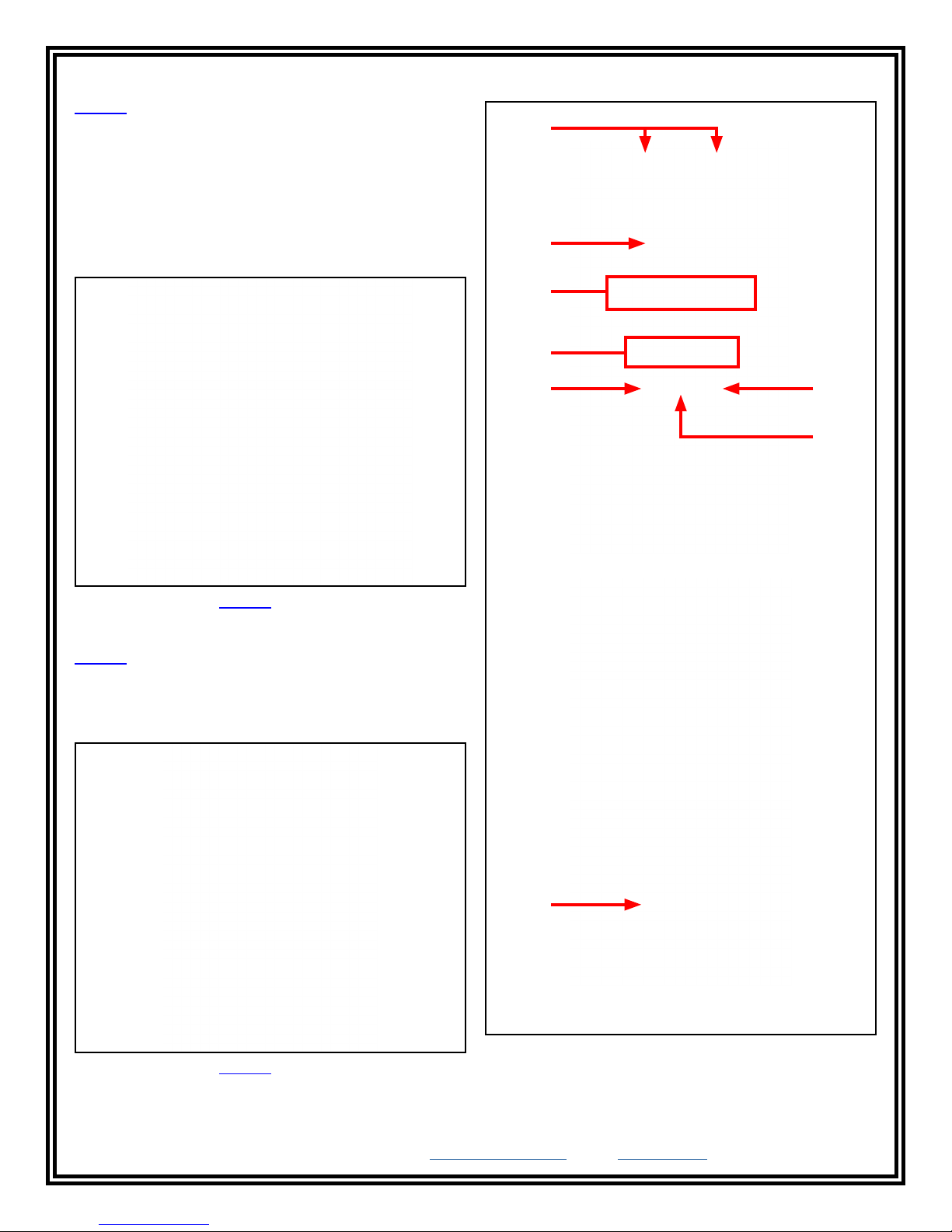
Features and Components
A
B
C
D
E F
G
Figure 2. Vermason 222642 Digital Surface Resistance
Meter Kit
222643 Digital Surface Resistance Meter
1 Digital Surface Resistance Meter
2 AA Alkaline Batteries
1 Certificate of Calibration
FRONT VIEW
H
REAR VIEW
Figure 3. Vermason 222643 Digital Surface Resistance
Meter
DESCO EUROPE - 2A DUNHAMS LANE, LETCHWORTH, HERTFORDSHIRE, SG6 1BE, UK
Phone: +44 (0) 1462 672005 • E-mail: Service@DescoEurope.com, Website: DescoEurope.com
TB-7588 Page 2 of 7
Figure 4. Digital Surface Resistance Meter features and
components
© 2017 DESCO INDUSTRIES, INC.
Employee Owned
A. Test Jacks: The shielded test leads connect here. The
black test lead’s 3.5mm plug connects into the stereo jack,
and the white test lead’s banana plug connects into the
banana jack.
B. Liquid Crystal Display: Temperature, Relative Humidity
and Resistance Mantissa values appear on this display.
When the test button is depressed and the meter is set to
FULL test mode, the following information will display in
sequence:
• Temperature in degrees Fahrenheit (±10%)
• Temperature in degrees Celsius (±10%)
• Relative Humidity as a percentage (±10 integers)
• Surface Resistance Mantissa (with exponent displayed
via LED, measurement in ohms)
Surface resistance ohm values are expressed with a
mantissa and exponent (power) of the number. For example,
if the #8 exponent LED illuminates and the meter displays
“7.14”, the measurement is 7.14 x 10⁸ ohms or 714,000,000
ohms.
F. Quick Check Button: When set to FULL, the meter will
cycle through the approximate 15 second electrification
period that displays the temperature and relative humidity
before the surface resistance mantissa is displayed. When
set to QUICK, the meter will skip the 15 second period
and immediately display the measured surface resistance
mantissa.
G. Test Button: Push and hold this red button to make a
measurement with the meter. Testing in accordance with
IEC 61340-2-3 requires 15 seconds of electrification. These
15 seconds are included when the meter is set to FULL test
mode. The surface resistance mantissa will display on the
meter after temperature and relative humidity measurements
are displayed.
The surface resistance exponent number illuminates
immediately, and the meter first displays the temperature
and relative humidity during a 15 second electrification
period. The mantissa is then displayed at the end of the test
sequence. For example, if the #8 exponent LED illuminates
and the meter displays “7.14”, the measurement is 7.14 x 10
ohms or 714,000,000 ohms.
If the measured surface resistance is over 1012 ohms, “1___”
will appear on the liquid crystal display.
H. Battery Compartment: Open this compartment to install
the two AA alkaline batteries needed to power the meter.
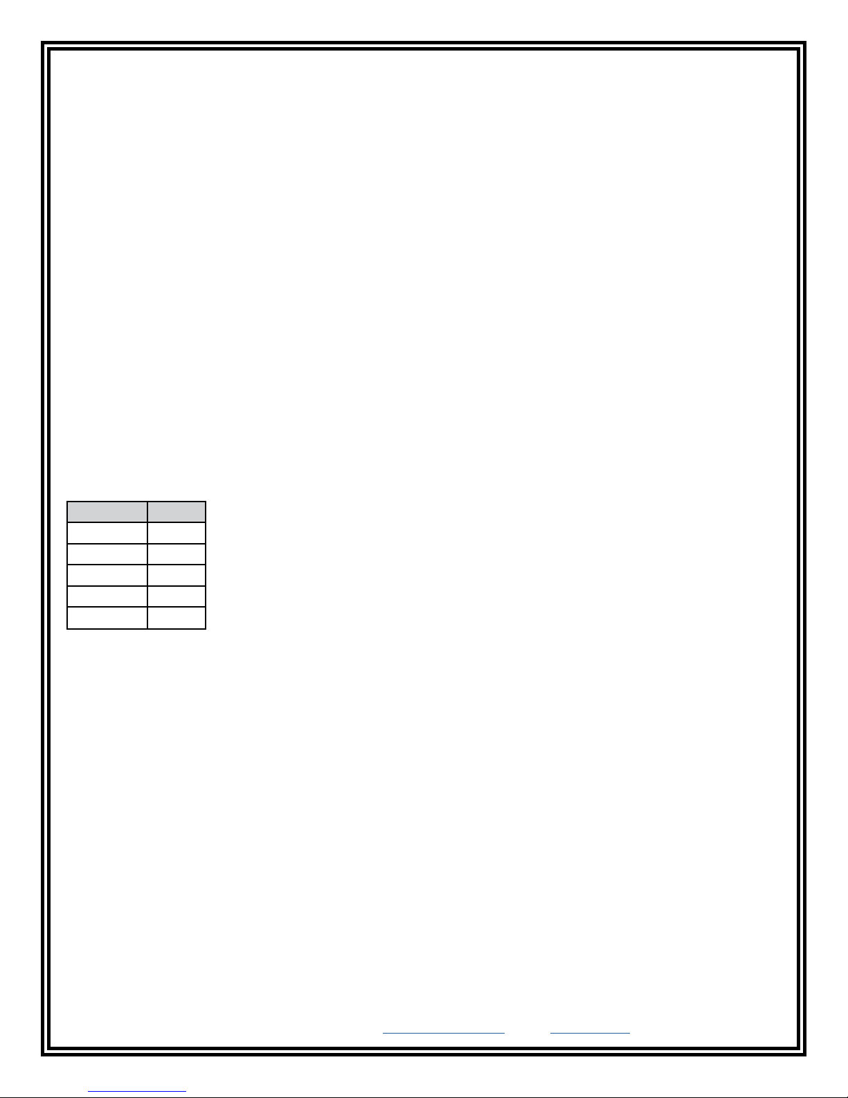
C. Exponent Light Emitting Diodes (LED): These LEDs
Replace the batteries once the Function LEDs begin flash.
indicate the surface resistance exponent value. They are
colour coded for quick checks.
Exponent Colour
<3, 3 Red
4, 5 Green
6, 7, 8 Blue
9, 10 Green
11, 12, >12 Yellow
Operation
Per IEC User Guide Testing of Installed ESD Control
Items
“Once the ESD ground reference has been verified it is
important to ensure that each of the ESD control items used
is connected to the ground reference. First ensure that each
ESD control item is connected to the ground reference. Next,
using the test method or standard and limits for each ESD
control item given in Tables 2 and 3 of IEC 61340-5-1,verify
that the resistance to ground (or to the common connection
Quick Checks
The surface resistance exponent number illuminates
immediately (i.e. 8 = 1 x 10⁸ ohms to less than 1 x 10⁹ ohms
or 100,000,000 to less than 1,000,000,000 ohms).
D. Function LEDs: These LEDs indicate the measurement
type displayed. The surface resistance mantissa is displayed
when either the “10V” or “100V” LED is illuminated.
The Function LEDs will flash when the battery voltage drops
point) meets the required limit”. (CLC/TR 61340-5-2 User
guide Grounding/bonding systems clause 4.4.5 Verification of
proper installation of ESD control items)
General Guidelines
• Use both 2 kg electrodes for Rp-p measurements.
• Use one 2 kg electrode and connect the black sensing
• Ensure that the item being measured is electrically
to approximately 2 volts. Replace the batteries when this
occurs.
E. Test Voltage Button: When set to AUTO, the meter will
• Ensure that the test leads are separated and uncrossed
automatically switch to the appropriate test voltage for the
measured resistance range. The Function LEDs will indicate
• When using 2 kg electrodes:
the applied test voltage. Material that is 9 x 10⁵ ohms or
less should be measured at 10 volts. Material that is 1 x
106 ohms or greater should be tested at 100 volts. (Ref: IEC
61340-2-3) When the switch is set to 10V HOLD, the test
voltage will be fixed at 10 volts regardless of the measured
resistance value.
8
test lead to ground for Rg measurements.
isolated (placed on an insulative surface). The meter will
measure the lowest resistance path.
as a best practice.
• Place them no closer than 5 cm from the edge of
the surface being measured
• Place them no closer than 8 cm to any groundable
point
• Place them about 25 cm apart from each other for
Rp-p measurements of a worksurface
• Place them about 1 m apart from each other for
Rp-p measurement of a floor
DESCO EUROPE - 2A DUNHAMS LANE, LETCHWORTH, HERTFORDSHIRE, SG6 1BE, UK
Phone: +44 (0) 1462 672005 • E-mail: Service@DescoEurope.com, Website: DescoEurope.com
TB-7588 Page 3 of 7
© 2017 DESCO INDUSTRIES, INC.
Employee Owned
 Loading...