

Verlinde TVI Series Instruction Manual
VERLINDE reserve the right to alter or amend the above information without notice
07/2016
ANGLAIS
INSTRUCTION MANUAL
ELECTRIC WINCH TVI SERIE
Product Distributed in Ireland by:
601, Western Industrial Estate,
Dublin 12, Ireland T: + 353 (
0)1
4584836 E: sales@prolift.ie
www.prolift.ie

2/30
03/2016
To ensure the constant improvement of its products, VERLINDE reserves the right to change the equipment as
described below and, in this case, to supply products which differ from the illustrations in this instruction manual.
All rights reserved
Summary
1 - Contents .................................................................................................................................................. 2
2 - What not to do ......................................................................................................................................... 3
3 - Compulsory regulatory inspections by the user ...................................................................................... 3
4 - Introduction to the machines ................................................................................................................... 4
5 - Handling - Storage .................................................................................................................................. 7
6 - Installation and start-up ........................................................................................................................... 7
7 - Servicing and maintenance ..................................................................................................................... 14
8 - Decommissioning .................................................................................................................................... 15
9 - Spare parts .............................................................................................................................................. 15
10 - Troubleshooting ....................................................................................................................................... 16
11 - Declaration of conformity ......................................................................................................................... 17
12 - Appendixes .............................................................................................................................................. 18
1 – Contents
All users are asked to read the start-up instructions carefully before using the winch for the first time. These
instructions will help the user to become familiar with the winch and to use it to the best of its capabilities. The
start-up instructions contain important information on how to use the winch in a safe and correct manner.
Observing these instructions can help prevent risks, minimize repair costs, reduce down time and increase the
reliability and useful life of the winch. The instruction manual must always be available at the winch operation
location. In addition to the start-up instructions and the regulations relating to accident prevention, it is important
to consider current rules in terms of TVIl safety and professional standards in force in each country.
This machine is covered by European regulations and, more specifically, machinery directive
2006/42/CE, EMC directive 2004/108/EC and low-voltage directive 2006/95/EC, as well as standard EN
14492/1.
The TVI Series winches can be used to perform lifting and pulling operations.
When used for lifting, European regulations require the use of certain equipment, including a limit stop and a
load limiter (above 1000 kg).
The user must make sure that this equipment is in place (optionally available from the manufacturer) before
undertaking any lifting operation.
Please ensure that the operator is qualified to operate the winch under the conditions laid down in this
manual. This is to respect the safety of workers and the environment.
The capacity indicated on the winch corresponds to the maximum operational capacity (M.O.C.), which may
not be exceeded in any case.
This winch may not be used to lift personnel under any circumstances.
Do not lift or carry loads while personnel remains in the danger zone.
Do not authorize personnel to walk under a hanging load.
Never leave a load hanging or under tension without supervision.
Never begin to handle a load without fixing it correctly and making sure that all personnel has left the danger
zone.
Before each use, the operator must check that the machine, its ropes, its hook, its markings and its restraints
are in good condition.

3/30
03/2016
The operator must make sure the load is hooked so that the winch, the rope and the load do not pose any
risk for him or other personnel.
The winches can be handled within a range of ambient temperatures between -10° C and +50° C. Please
consult the manufacturer in the case of extreme operating conditions.
Warning: When the ambient temperature is less than 0°C, the brake must be tested in order to make sure it
has no operating faults caused by frost.
All uses of the winches must strictly conform to accident prevention and safety measures for the country
where they are being used.
The manufacturer accepts no responsibility for the consequences of the machines being used or installed in
ways other than described in the manual, or for the consequences of altering or replacing original parts or
components with parts or components from other sources without its written agreement.
YOU ARE ALSO REQUIRED TO OBSERVE THE APPLICABLE RECOMMENDATIONS IN YOUR
COUNTRY.
2 - What not to do
Before using the winch, make sure there is no risk of overloading due to adherence to the floor, suction,
jamming, etc. of the load. In addition to the above, avoid all the incorrect uses and operations indicated
below. It is dangerous and prohibited to:
unwind the drum completely (always leave 2 to 3 coils).
pull at an angle.
swing the load.
use ropes with a diameter and texture that do not comply with the specifications of this manual (FEM 1 Am –
ISO M4)
use damaged or spliced ropes.
use hooks without catches, not suitable for the loads specified on the winch, or in bad condition.
insert objects into the moving parts.
service winches while they are loaded or receiving power.
use the rope of the machine as a sling.
tap on the control box (heating the motor and the electrical controls).
3 – Compulsory regulatory inspections by the user
This equipment has been designed to be subjected to the following tests:
Dynamic proof test at coefficient 1.1
Static proof test at coefficient 1.25
Users are required to conform to the regulations in force in their own countries.
In the case of France:
Order of 1 March 2004 on the testing of lifting machines and accessories:
The amendments to the regulations regarding the use and testing of lifting machines and accessories, in force
since 1 April 2005, impose new obligations on all users:
Adaptation exam, which consists of checking that the lifting machine is suitable for the work the user intends
to carry out as well as for the risks to which the workers are exposed and that the planned operations are
compatible with the conditions for using the machine as defined by the manufacturer.
Assembly and installation exam, which consists of making sure that the lifting machine is assembled and
installed in a safe manner, in accordance with the manufacturer's instruction manual.

4/30
03/2016
Periodic general inspections, including an exam of the state of conservation and operating tests.
Tests for starting or restarting service in the event of changing the operation site, changing the configuration
or the conditions for use on the same site, following dismantlement and reassembly of the lifting machine,
after any considerable replacement, repair or transformation affecting the core components of the lifting
machine, following any accident caused by a failure in a core component of the lifting machine.
The tests must be performed in strict observance of protocol. They aim to provide preventive maintenance,
detecting any damage or faults that can create a risk.
VERLINDE provides an upkeep / maintenance manual for each piece of equipment. It is very important to make
sure that the individuals using the hoist are familiar with the equipment and its correct operation.
VERLINDE agencies are available and may, upon request or by contract, intervene and maintain the winch if
necessary.
If any replacement parts are needed, please specify the following information so that we may supply the
appropriate parts:
- the complete name of the winch
- the complete name of the hoisting motor if necessary
- the serial number of the winch
The 3 items above are listed on the ID plates attached to the winch, motors and on the inspection certificates.
For further information, please contact the winch manufacturer or the distributor.
Manufactured by :
Manufactured by:VERLINDE
VERNOUILLET- FRANCE
2, Boulevard de l'industrie
B.P. 59 28501 VERNOUILLET CEDEX
Phone: +33 (0)2.37.38.95.95
Fax: +33 (0)2.37.38.95.99
4 – Introduction to the machines
4.1 - General
These winches are designed for pulling or lifting loads from 1000 to 10000 kg.
Their FEM classification is 1 Am (ISO: M4)
The TVI Series winches are equipped with the following:
Reduction gear with planetary gears, completely watertight.
Motor 1 speed, three-phase 230/400 V 50 Hz, protection rating IP 55. Operating limits from -10ºC to
+50ºC (without declassification).
24 V very-low voltage control including:
Contactors
Power line isolator
Thermal circuit breaker
Disconnectable button box (2 buttons + emergency stop), 3 m of cable.
5/30
03/2016
Very-low voltage control with variable speed drive (compulsory above 5 tons), comprising:
Power line isolator
Variable-frequency drive
Braking resistance
Button box (2 buttons + emergency stop + potentiometer), not disconnectable, 3 m of cable.
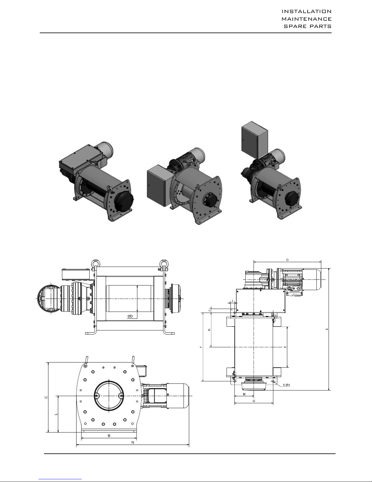
4.2 - Dimensions
Depending on models :
Above the motor (1) on its side (2) or away (3)

6/30
03/2016
a. Low voltage control – Models with 1 speed
b. Low voltage control – Models with frequency inverter
4.3 - Models available
Warning: . the rope diameter shown above corresponds to the recommended rope according to FEM 1 Am /
ISO M4 classification. It also corresponds to the capacity on the last layer.
. it is compulsory to ensure that the resistance coefficient of the rope complies with the lifted load
(FEM 1 Am / ISO M4).
TVI
1 T
2 T
3 T
4 T
5 T
6 T
7 T
8 T
9 T
10 T
05BT/10BT
05BT/09BT
03BT/06BT
02BT/05BT
03BT/07BT
02BT/06BT
02BT/06BT
02BT/05BT
02BT/05BT
03BT/05BT
Position of the electrical unit
(1)
(1)
(1)
(1)
(1) / (2)
(1) / (3)
(1) / (2)
(1) / (2)
(1) / (2)
(1) / (2)
A in mm
911
1050/1045
1065/1090
1169/1194
1194/1220
1224/1250
1241/1267
1241/1267
1288/1087
1314/1288
B in mm
290
420
420
520
520
650
700
700
840
840
C in mm
375
500
500
665
665
765
870
870
975
975
D in mm
125
219,1
219,1
292
292
323,9
355,6
355,6
406,4
406,4
E in mm
350
350
350
350
350
350
350
350
350
350
F in mm
525
590
590
600
600
600
720
720
720
720
G in mm
240
330
330
420
420
420
620
620
750
750
H en mm
12
16
16
22
22
22
30
30
32
32
I in mm
25
45
45
50
50
115
40
40
45
45
J in mm
23
32
32
30
30
30
50
50
47
47
K in mm
263
295
295
300
300
300
360
360
360
360
L in mm
188
262
262
350
350
395
455
455
515
515
M in mm
120
165
165
210
210
210
310
310
375
375
N in mm
716/748
823/902
823/902
905/984
954/1190
1013/1181
1103/1271
1133/1271
1176/1314
1176/1314
0 in mm
548/578
578/657
578/657
578/657
627/795
627/795
662/830
692/830
692/830
692/830
TVI
1 T
2 T
3 T
4 T
5 T
6 T
7 T
8 T
9 T
10 T
05VV/10VV
05VV/09VV
03VV/06VV
02VV/05VV
03VV/07VV
02VV/06VV
02VV/06VV
02VV/05VV
02VV/05VV
03VV/05VV
Position of the
electrical unit
(1)
(1) / (3)
(1) / (3)
(1) / (2)
(2) / (3)
(2)
(2)
(2)
(2)
(2)
A in mm
911
1050/1045
1065/1090
1169/1194
1194/1220
1224/1250
1241/1267
1241/1340
1288/1087
1288/1367
B in mm
290
420
420
520
520
650
700
700
840
840
C in mm
375
579/500
579/500
737/665
665
765
870
870
975
975
D in mm
125
219,1
219,1
292
292
323,9
355,6
355,6
406,4
406,4
E in mm
350
350
350
350
350
350
350
350
350
350
F in mm
525
590
590
600
600
600
720
720
720
720
G in mm
240
330
330
420
420
420
620
620
750
750
H en mm
12
16
16
22
22
22
30
30
32
32
I in mm
25
45
45
50
50
115
40
40
45
45
J in mm
23
32
32
30
30
30
50
50
47
47
K in mm
263
295
295
300
300
300
360
360
360
360
L in mm
188
262
262
350
350
395
455
455
515
515
M in mm
120
165
165
210
210
210
310
310
375
375
N in mm
716/748
823/902
823/902
905/1052
1022/1122
1067/1220
1103/1271
1133/1271
1176/1314
1176/1314
0 in mm
548/578
578/657
578/657
578/657
627/795
627/795
662/830
692/830
692/830
692/830

7/30
03/2016
TVI
Low voltage control – Models with 1 speed
1 T 2 T 3 T 4 T 5 T
05BT
10BT 05BT
09BT 03BT
06BT 02BT
05BT 03BT
07BT
Capacity on the 1rst layer kg
1255 2420 3765 4985 6230
Capacity on the last layer (kg)
1000 2000 3000 4000 5000
Nb of layers
3 3 3 3 3
Wire rope capacity at 1rst layer
m *
17 20 16 16 16
Max. rope capacity (m)
60 71 59 60 60
Rope diameter (mm)
8 11,5 14 18 18
Speed on the 1rst layer m/min
4
8,5 4,5
8 2,5
4,5 2
3,5 2,5
6
Speed on the last layer (m/min)
5
10,5 5,5
9,5 3,5
5,5 2,5
4,5 3
7,5
FEM
1Am 1Am 1Am 1Am 1Am
Motor (kW)
1,1
2,2 2,2
4 2,2 4
2,2
4 3
9,2
Supply
3 Ph - 230/400
V
3 Ph - 230/400 V
3 Ph - 230/400 V
3 Ph - 230/400 V
3 Ph - 230/400 V
Weight (winch without wire
rope) kg
140
150 260
280 260
280 440
470 450
530
TVI
Low voltage control – Models with 1 speed
6 T 7 T 8 T 9 T 10 T
02BT
06BT 02BT
06BT 02BT
05BT 02BT
05BT 03BT
05BT
Capacity on the 1rst layer kg
7480 8725 9975 11120
12355
Capacity on the last layer (kg)
6000 7000 8000 9000
10000
Nb of layers
3 3 3 3 3
Wire rope capacity at 1rst layer m *
16 15 15 16 16
Max. rope capacity (m)
60 60 60 62 62
Rope diameter (mm)
20 22 22 24 24
Speed on the 1rst layer m/min
1,5
5 1,5
4,5 2
4 1,5
4 2
3,5
Speed on the last layer (m/min)
2
6 2
5,5 2,5
5 2
4,5 2,5
4,5
FEM
1Am 1Am 1Am 1Am 1Am
Motor (kW)
3
9,2 3
9,2 4
9,2 4
9,2 5,5
9,2
Supply
3 Ph - 230/400 V
3 Ph - 230/400 V
3 Ph - 230/400 V
3 Ph - 230/400 V
3 Ph - 230/400 V
Weight (winch without wire rope) kg
580
660 840
910 850
910 1160
1230 1180
1230
TVI
Low voltage control – Models with frequency inverter
1 T 2 T 3 T 4 T 5 T
05VV
10VV 05VV
09VV 03VV
06VV 02VV
05VV 03VV
07VV
Capacity on the 1rst layer kg
1255 2420 3765 4985 6230
Capacity on the last layer (kg)
1000 2000 3000 4000 5000
Nb of layers
3 3 3 3 3
Wire rope capacity at 1rst layer
m *
17 20 16 16 16
Max. rope capacity (m)
60 71 59 60 60
Rope diameter (mm)
8 11,5 14 18 18
Speed on the 1rst layer m/min
4
8,5 4,5
8 2,5
4,5 2
3,5 2,5
6
Speed on the last layer (m/min)
5
10,5 5,5
9,5 3,5
5,5 2,5
4,5 3
7,5
FEM
1Am 1Am 1Am 1Am 1Am
Motor (kW)
1,1
2,2 2,2
4 2,2 4
2,2
4 3
9,2
Supply
3 Ph - 230/400
V
3 Ph - 230/400 V
3 Ph - 230/400 V
3 Ph - 230/400 V
3 Ph - 230/400 V
Weight (winch without wire
rope) kg
150
155 270
300 270
300 450
500 480
540

8/30
03/2016
TVI
Low voltage control – Models with frequency inverter
6 T 7 T 8 T 9 T 10 T
02VV
06VV 02VV
06VV 02VV
05VV 02VV
05VV 03VV
05VV
Capacity on the 1rst layer kg
7480 8725 9975 11120
12355
Capacity on the last layer (kg)
6000 7000 8000 9000
10000
Nb of layers
3 3 3 3 3
Wire rope capacity at 1rst layer m *
16 15 15 16 16
Max. rope capacity (m)
60 60 60 62 62
Rope diameter (mm)
20 22 22 24 24
Speed on the 1rst layer m/min
1,5
5 1,5
4,5 2
4 1,5
4 2
3,5
Speed on the last layer (m/min)
2
6 2
5,5 2,5
5 2
4,5 2,5
4,5
FEM
1Am 1Am 1Am 1Am
1Am
Motor (kW)
3
9,2 3
9,2 4
9,2 4
9,2 5,5
9,2
Supply
3 Ph - 230/400 V
3 Ph - 230/400 V
3 Ph - 230/400 V
3 Ph - 230/400 V
3 Ph -
230/400 V
Weight (winch without wire rope) kg
610
670 870
920 880
920 1190
1250
1210
1250
* Rope and hook extra.
The diameter of the wire rope corresponds to the capacity on the last layer
4.4 - Options
The TVI Series winches can be supplied with the following options:
Clock-type limit switch
Easily adjustable, this system guarantees safety by setting top and bottom limits.
IP 65 limit switch
Electronic load limiter
Device with display which stops the winch in the event of an overload without breaking the kinematic chain.
Slotted drum
Enables correct winding of the rope on the first layer.
Secondary brake
Emergency trouble shooting hand wheel
Multi rope grooved drum
Lower chassis
Tarpauline cover
Special paint (C4, C5M)
Rope presser roller
Essential complement for the slotted drum if the rope is not permanently tight.
Manual unblocking of the brake with automatic return
Manual control
Handwheel or crank associated with a brake unblocking system.
Rope-slack switch
Detects rope that is not under tension.
2
nd
rope attachment
Option for creating a back-and-forth system or for lifting a load at two points.
Timer
Allows the user to add up the total time of winch operation and makes it easier to use the maintenance log.
Phase order detector
Allows the winch not to be connected with raising / lowering inversion.
Hauling radio control
Adjustable speed drive hauling radio control
Lifting radio control
Proportional adjustable speed drive lifting radio control
Any other requirements : consult us.
9/30
03/2016
4.5 - Classification FEM
There are eight groups of mechanisms:
FEM
1 Dm
1 Cm
1 Bm
1 Am
2m
3m
4m
5m
ISO
M 1
M 2
M 3
M 4
M 5
M 6
M 7
M 8
To determine the group of a given lifting device, winch or hoist, three essential parameters must be
considered:
4.5.1. - Maximum load to be lifted
Including the weight of the rope and any lifting accessories used (hook, etc.) unless these have a total
weight equal to or less than 5% of the load to be lifted.
4.5.2. - Strain condition
Specifies the proportions in which the lifting machine is used with maximum load or reduced load. Four
characterized strain conditions are identified in this way:
Light
Lifting machines exceptionally subjected to the maximum
strain and commonly to very light strains.
k ≤ 0.5
Medium
Lifting machines often subjected to the maximum strain
and commonly to light strains.
0.5 < k ≤ 0.63
Heavy
Lifting machines frequently subjected to the maximum
strain and commonly to medium strains.
0.63 < k ≤ 0.8
Very
heavy
Lifting machines regularly subjected to the strains near to
the maximum strain.
0.8 < k ≤ 1
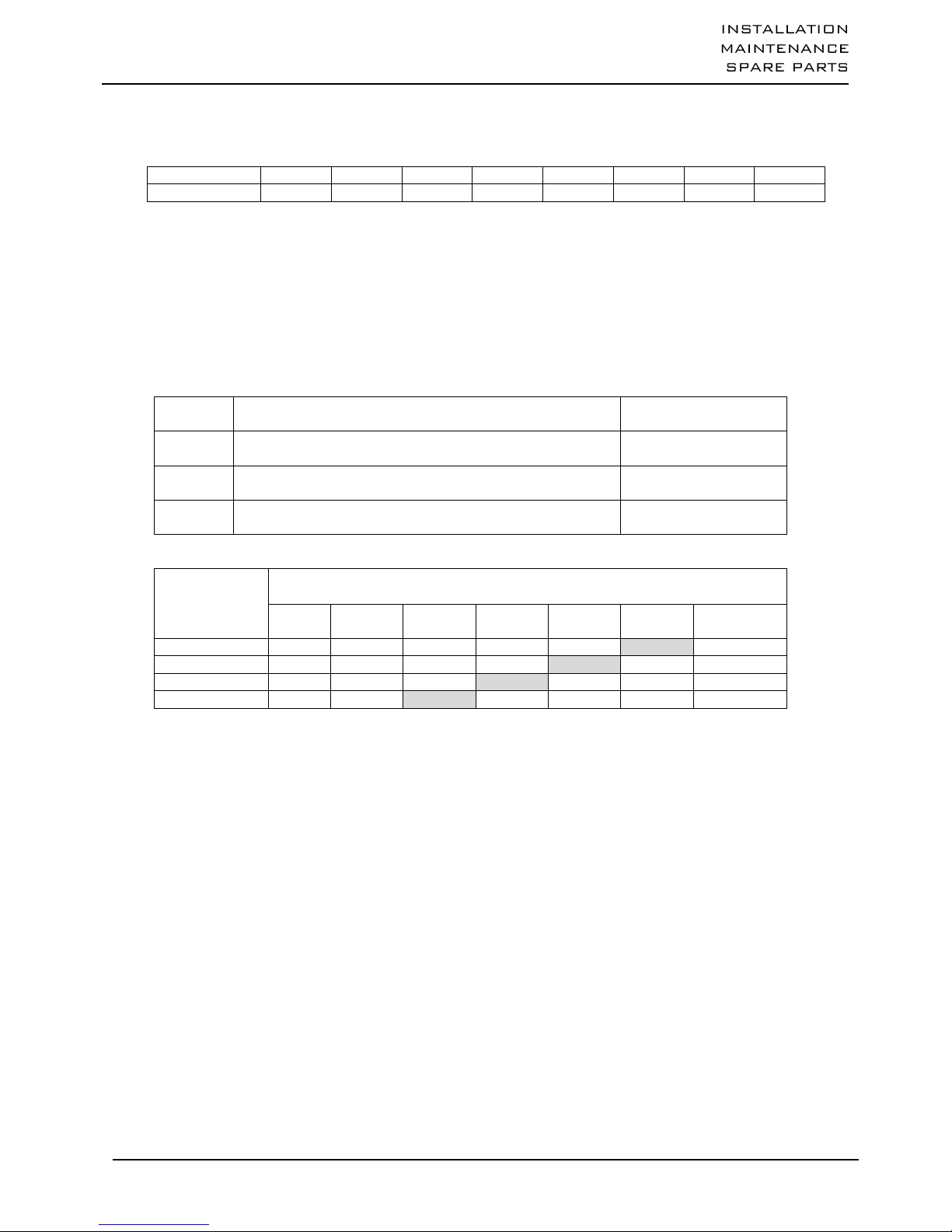
4.5.3. – FEM classification
Strain
condition
Average operating time per day, in hours
30’
1 h
2 h
4 h
8 h
16 h
More than
16 h
Light
1 Dm
1 Cm
1 Bm
1 Am
2m
3m
4m
Medium
1 Cm
1 Bm
1 Am
2m
3m
4m
5m
Heavy
1 Bm
1 Am
2m
3m
4m
5m
Very heavy
1 Am
2m
3m
4m
5m
5 – Handling - Storage
When handling the winch, use slings that are compatible with the slinging points provided for this purpose on
the winch.
Warning: the angle formed between the hook and the two slinging points must be at most 45º.
Lift and set down the winch with care, without letting it fall, bearing in mind the offset centre of gravity.
For further information on the weight of the winch, consult the Technical Specifications chapter.
These winches must be protected from the elements, in a dry and clean location, at temperatures comprised
between -10ºC and +50ºC.
 Loading...