

Verlinde STAGEMAKER SM1 128M1-A, STAGEMAKER SM5 258 M1-A, STAGEMAKER SM2 254 M1-A, STAGEMAKER SM5 254 M1-A, STAGEMAKER SM5 504 M1-A Technical Manual
...
STAGEMAKER® LINE
VERLINDE se réserve le droit de modifier sans préavis les caractéristiques de son matériel
VERLINDE reserve the right to modify or improve equipment described in this document
11/2008GT FR/GB
GUIDE
TECHNIQUE
TECHNICAL GUIDE
PALAN ELECTRIQUE A CHAINE ET CONTROLEUR
ELECTRIC CHAIN HOIST AND CONTROLLER
STAGEMAKER® LINE
GUIDE TECHNIQUE
TECHNICAL GUIDE
Page 2
VERLINDE se réserve le droit de modifier sans préavis les caractéristiques de son matériel
VERLINDE reserve the right to modify or improve equipment described in this document
11/2008 VESAFR/GBSM04A
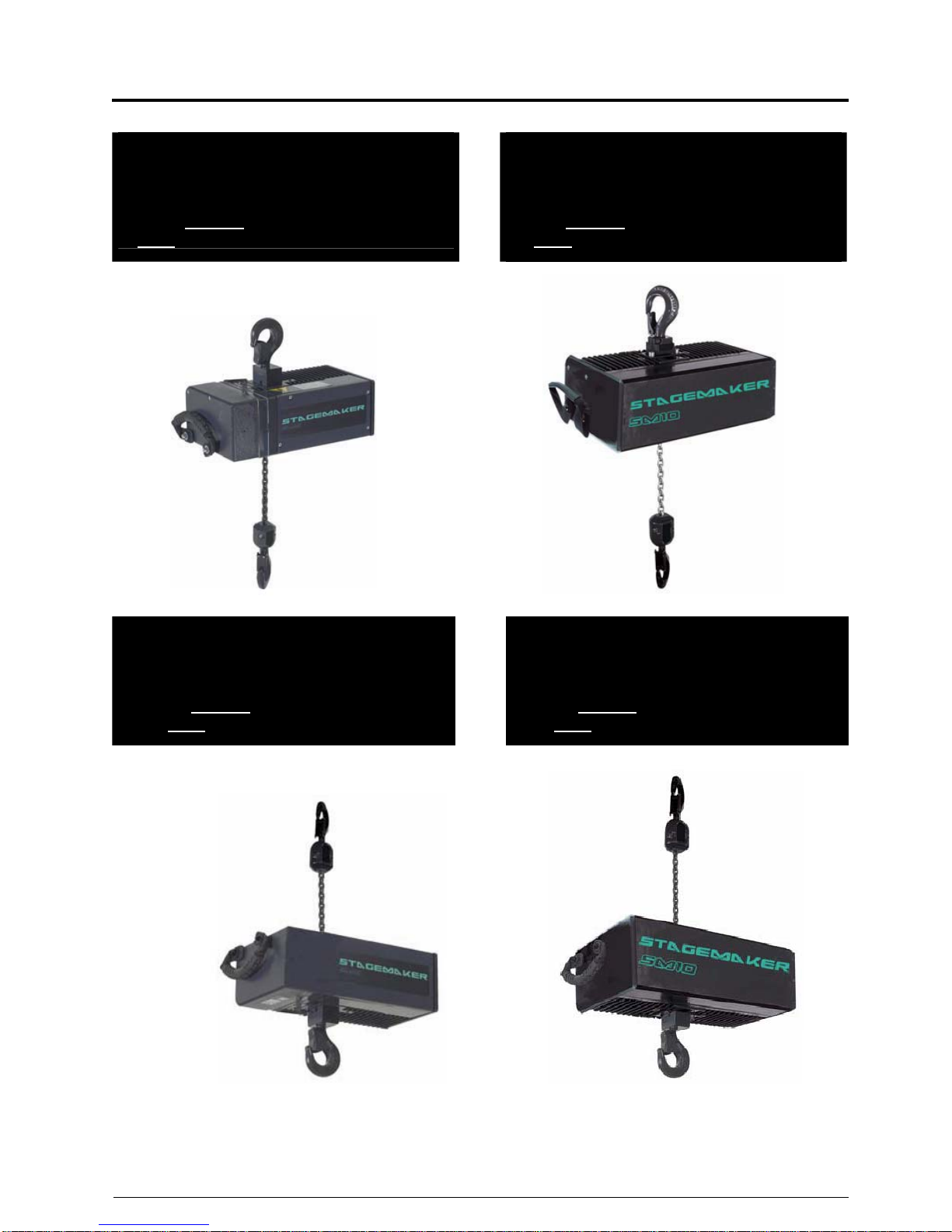
PALANS DISPONIBLES
EN POSITION NORMALE
(corps de palan en haut)
Version : A-B-C-D-E-V et S
Type : SM1-SM2-SM5-SM10 et SM16-25
HOISTS AVAILABLE
IN NORMAL POSITION
(body upwards)
Version : A-B-C-D-E-V and S
Type : SM1-SM2-SM5-SM10-SM16-25
PALANS DISPONIBLES
EN POSITION INVERSEE *
(corps de palan en bas)
Version : A-B-C-D-V et E
Type : SM1-SM2-SM5 ET SM10
HOISTS AVAILABLE
IN INVERTED POSITION *
(body downwards)
Version : A-B-C-D-V and E
Type : SM1-SM2-SM5 AND SM10
* dans cette configuration, le palan peut être également utilisé en version normale (corps de
palan en haut)
* in this configuration, the hoist can also be used in normal position (body upwards)

STAGEMAKER® LINE
GUIDE TECHNIQUE
TECHNICAL GUIDE
Page 3
VERLINDE se réserve le droit de modifier sans préavis les caractéristiques de son matériel
VERLINDE reserve the right to modify or improve equipment described in this document
11/2008 VESAFR/GBSM04A
SOMMAIRE
INDEX
Introduction
- Applications mobile
- Applications fixe
- Codification
5
5
6
9
Introduction
- Mobile applications
- Fixed applications
- Codification
Configurations de base
10 Basic configurations
Versions de palans
- Version A et B Palan standard
- Version S Palan monophasé
- Version C pour contrôle avec CPU
- Version D pour application BGV-C1
- Version E sans appareillage électrique
- Version V avec variateur
12
12
13
14
16
17
18
Hoist versions
- Version A and B Standard hoist
- Version S Single phase hoists
- Version C Hoists for CPU control
- Version D BGV-C1 hoists
- Version E Hoist without electrics
- Version V Hoist with inverter
Détails Techniques
- Version A
- Version B
- Version C
- Version D
- Version E
- Version V
- Version S
20
20
22
24
26
29
31
32
Technical details
- Version A
- Version B
- Version C
- Version D
- Version E
- Version V
- Version S
Points à prendre en considération
33 Points to observe
Contrôleurs
- Version A
- Version B
- Version C
- Version D
- Version V
35
35
39
41
43
45
Controllers
- Version A
- Version B
- Version C
- Version D
- Version V
Exemples d’utilisations
- Version A
- Version B
- Version C
- Version D
- Version V
46
46
53
54
55
56
Examples of use
- Version A
- Version B
- Version C
- Version D
- Version V
Tableau de sélection des câbles et options 57 Cable selection tables and options
Limiteur de charge
66 Overload devices
Fin de course de levage
67 Limit switches
Codeur incrémental
69 Incremental encoders

STAGEMAKER® LINE
GUIDE TECHNIQUE
TECHNICAL GUIDE
Page 4
VERLINDE se réserve le droit de modifier sans préavis les caractéristiques de son matériel
VERLINDE reserve the right to modify or improve equipment described in this document
11/2008 VESAFR/GBSM04A
INTRODUCTION
INTRODUCTION
Les palans STAGEMAKER peuvent être
utilisés en versions inversées (corps du palan
en bas) et non inversées (corps du palan en
haut), en installations fixes ou mobiles.
Chaque type d’application possède ses
caractéristiques propres qui doivent être
prisent en considération avant la commande
des palans, ceci afin d’éviter toutes sources
de confusion et d’éventuelles erreurs.
STAGEMAKER hoists could be used in
normal upright (body up), or inverted position
(body down), in mobile or in permanent
installations. Each of these applications do
have their particular circumstances which
have to be taken in consideration before
ordering, this to avoid misunderstanding and
disappointments.
Applications mobiles :
• En tournée
• Supports de structures
• Salons et défilés de mode
• Présentations de produit
• Cirque
• Applications industrielles :
• Elévation d’ascenseur, structures
métalliques etc.
• Maintenance, station de traitements des
eaux, etc…
Mobile applications :
• On tour entertainment
• Ground- and roof-supports
• Exhibitions and mode shows
• Product presentations
• Circus
• Industrial purposes
• Erection aide for elevators, steel structures
etc.
• Service applications, water treatment
stations, etc.
Dans la plupart des cas un palan en tension
directe peut effectuer le travail, à condition
qu’il n’y ai pas de législation locale spécifique
ou d’exigence particulière de sécurité.
L’avantage majeur du palan en version A est
la simplicité du système de contrôle et du
câblage (1 câble). Les palans peuvent être
utilisés dans les 2 versions (inversée et non
inversée) en changeant la position du bac à
chaîne.
In most of these cases, a direct controlled
hoist can do the job, provided that there are
no local additional regulations or requirements
in terms of safety.
The major advantage of this hoist version A is
the simplicity of the controls and intermediary
cabling. (single cable). The hoists could be
used both way, upright or inverted, just by
changing the position of the chain-bucket.
Les équipements en tournée doivent rester
simples et faciles à installer avec un minimum
de câblage. Les palans avec tension directe
(version A) sont la solution économique !
Facilité d’élévation et d’installation
• L’ensemble du câblage est au même
niveau
• Contrôle de palan par groupe facilité
• Le palan est à la hauteur de la structure
showbiz
On-tour equipment must be kept simple, easy
to erect and with a minimum of cabling.
Inverted hoists with direct control (version A)
are therefore the most economical solution !
Easy erection and instalment
• All cabling at same level
• Easy group control
• Hoist at truss level
Note :
La législation locale concernant la sécurité
doit être respectée en toutes circonstances !
Note :
Local regulations in terms of safety
requirements should be respected at any time!

STAGEMAKER® LINE
GUIDE TECHNIQUE
TECHNICAL GUIDE
Page 5
VERLINDE se réserve le droit de modifier sans préavis les caractéristiques de son matériel
VERLINDE reserve the right to modify or improve equipment described in this document
11/2008 VESAFR/GBSM04A
Cette législation peut imposer pour :
These regulations could require :
Les applications statiques
Des élingues de sécurité complémentaires
entre le point haut de suspension et le crochet
inférieur (Les élingues doivent être résistantes
au feu !)
Ou le facteur de sécurité doit être de 10
ou de 8 (capacité déclassées de 50%) avec un
double frein (BGV-D8
+
)
Il n’y a pas de spécifications particulières
requises concernant les contrôleurs.
Static applications
Additional safety slings between upper
suspension point and lower hook (Slings must
be fire proof !)
Or safety factor 10 or 8 achieved by down
rating the capacity with 50% and double brake
(BGV-D8
+
)
No specific requirements are valid with
respect the controllers.
Les applications dynamiques
Le respect du code VLPT-SR 2.0 ou
l’application de la BGV-C1 effectif sur les
palans et les contrôleurs.
Dynamic applications
Compliance to specific codes of practice like
BGV-C1 or VLPT-SR 2.0. for hoist as well as
for controllers.
Applications Fixes :
• Théâtres
• Studio de TV et cinéma
• Salle de concert, variétés
• Discothèque
• Application Multiple – Salle de conférences
• Stade (Intérieur - Extérieur)
Fixed applications:
• Theatres
• TV and film studio’s
• Amusement- concert halls
• Discotheque
• Multi purpose - conference halls
• Sports arenas (indoor - outdoor)
Dans ce type d’application le palan est en
dehors du champ de vision de l’utilisateur, il est
donc important que le palan intègre des
éléments de sécurité tels que des fins de
course électriques. La commande basse
tension est nécessaire dans ce cas.
Since the hoists in these applications usually
are out of sight, it is important to apply
additional safety elements such as endswitches. Low-voltage control is compulsory in
these cases.
Les installations fixes doivent souvent
présenter des caractéristiques supplémentaires
du fait de l'application elle-même et des
conditions locales. Dans les installations fixes,
les palans peuvent être suspendus à des
structures portatives ou à des chariots à
commande manuelle ou électrique.
Utiliser les palans “STAGEMAKER” en position
normale avec la commande très basse tension
standard version B.
Fixed installations, requires often additional
features because of the typical application and
local conditions. In permanent installations
hoists could be suspended from portable
stools, manual- or electric trolleys.
Use “STAGEMAKER” hoists in normal
position, with standard low voltage control
version B.
L'utilisation de contacts de fin de course
électriques est recommandée lorsque :
- la hauteur libre est limitée
- le palan n'est pas dans le champ de vision
- il y a des obstructions intermédiaires
Electrical end switches are to be advised in
case of :
- Limited headroom
- Hoist out of sight
- Intermediary obstructions

STAGEMAKER® LINE
GUIDE TECHNIQUE
TECHNICAL GUIDE
Page 6
VERLINDE se réserve le droit de modifier sans préavis les caractéristiques de son matériel
VERLINDE reserve the right to modify or improve equipment described in this document
11/2008 VESAFR/GBSM04A
Note :
Si les palans sont fixes, et donc suspendus en
permanence, des contacts de fin de course
externes ordinaires peuvent être utilisés pour
limiter les positions supérieure et inférieure
maximales, à condition que le crochet puisse
monter et descendre jusqu'au bout. Si le
crochet doit rester à une certaine distance du
corps du palan, il faut installer un frein de
chaîne entre le corps du palan et le moufle.
L'utilisation de ce frein de chaîne
supplémentaire n'est possible qu'avec les
moufles à un brin !
Dans tous les autres cas, utiliser des fins de
course à cames.
Bien tenir compte des points suivants :
- Il existe des fins de course différents selon la
longueur de la chaîne (voir tableau)
- Les fins de course à cames présentent une
certaine hystérésis ; ils doivent parcourir au
moins 500 mm dans le sens opposé avant
réinitialisation.
Note :
If the hoists are fixed and thus permanent
suspended, the standard external endswitches could be used to limit the extreme
upper and lower position, provided that the
hook can go up & down all the way. If the
hook has to stay a certain distance from the
hoist body, an extra chain-stop has to be fitted
between hoist body and hook-block. This
additional chain-stop is only possible in case
of single fall units !
In all other cases use the geared limit-switch
option.
Following points needs to be taken in
consideration :
- For different chain-length there are different
switches (see table)
- Gear-train limit-switches do have a certain
hysteresis, before the switch resets itself,
one has to run min. 500 mm in the opposite
direction.
Caractéristiques de sécurité
supplémentaires à envisager au cas par
cas
• Contacts thermiques
• Doubles freins
• Fins de course sécurité
• Limiteurs de charge électriques
Additional safety features to be considered
case by case
• Thermal contacts
• Double brakes
• Safety limit switches
• Electric overload device
Pour les installations fixes, la conception du
coffret électrique demande parfois un soin
particulier. Dans les salles de spectacle en
particulier, il est courant d'utiliser des coffrets
à montage mural. Dans ce cas, le câblage
intermédiaire (palan / commande) est
raccordé sur des bornes et non par des
connecteurs.
Si les palans sont destinés à des applications
multiples à l'intérieur d'un bâtiment, il est
conseillé de conserver une certaine souplesse
à l'installation. Dans ce cas, les palans à
commande directe sont recommandés ! (Voir
applications mobiles.)
For fixed installations, the execution of the
control panel sometimes requires additional
attention. Especially in theatres it is common
to use wall mounted cabinets. In such cases
the intermediary cabling (hoist versus
controller) is fitted on terminals, not through
connectors.
If hoists are to be used for multipurpose
applications in side the building, it is to be
advised to keep the installation flexible. In
such cases direct control hoist are
recommended! (see mobile applications)
Note :
La législation locale concernant la sécurité
doit être respectée en toutes circonstances
Note :
Local regulations in terms of safety
requirements should be respected at any time.

STAGEMAKER® LINE
GUIDE TECHNIQUE
TECHNICAL GUIDE
Page 7
VERLINDE se réserve le droit de modifier sans préavis les caractéristiques de son matériel
VERLINDE reserve the right to modify or improve equipment described in this document
11/2008 VESAFR/GBSM04A
Cette législation peut imposer pour :
Les applications statiques :
Des élingues de sécurité supplémentaires
entre le point haut de suspension et le crochet
inférieur (les élingues doivent être résistantes
au feu)
Ou, le facteur de sécurité doit être de 10 ou
de 8 (capacité déclassée de 50%), avec un
double frein, (BGV-D8
+
).
Il n’y a pas de spécifications particulières
Requises concernant les contrôleurs.
Les applications dynamiques :
Le respect du code VLPT-SR 2.0 ou
l’application de la BGV-C1, effectifs sur les
palans et les contrôleurs
These regulations could require :
Static applications:
Additional safety slings between upper
suspension point and lower hook (Slings must
be fire proof !.
Or safety factor 10 or 8 achieved by down
rating the capacity with 50% and double brake
(BGV-D8
+
)
No specific requirements are valid with
respect the controllers.
Dynamic applications :
Compliance to specific codes of practice like
BGV-C1 or VLPT-SR 2.0. for hoist as well as
for controllers.
Nota :
Dans le cas de palans programmables, il est
évident que les palans et les commandes
doivent prévoir des aménagements spéciaux
(voir palans et commandes version C – D et
V).
Note:
If programmable hoists are at stake, it is
obvious that hoists as well controllers require
special provisions. (see hoists & controllers
version C – D and V)

STAGEMAKER® LINE
GUIDE TECHNIQUE
TECHNICAL GUIDE
Page 8
VERLINDE se réserve le droit de modifier sans préavis les caractéristiques de son matériel
VERLINDE reserve the right to modify or improve equipment described in this document
11/2008 VESAFR/GBSM04A
INTRODUCTION
INTRODUCTION
Codification :
Codification :
SM5.50 4 M 1-B
SM5.50 4 M 1-B
- B
Type de commande :
- A = Tension directe
(ACF)
- B = 48v
- C = 48v,controle par
CPU
- D = 48v pour appl.BGV-
C1
- E = sans app. Electrique
- F = vitesse variable +
CPU « Cyberhoist »
- V = vitesse variable +
conctrôle
CPU possible en option
S = Mono phase
- B Type of control :
- A = direct control (ACF)
- B = 48v
- C = 48v for CPU control
- D = 48v for BGV-C1
appl.
- E = without controls
-F = variable speed +
CPU “Cyberhoist”
-V = variable speed
Possibility of CPU
control in option
-S = Single phase
1
Groupe FEM :
- 1 = 1Bm
- 2 = 2m
1
FEM group :
- 1 = 1Bm
- 2 = 2m
M
M : 1 vitesse de levage
B : 2 vitesses de levage
V : Variation de vitesse de levage
M
M: single hoisting speed
B: 2 hoisting speeds (special)
V: variable hoisting speed
4
Vitesse de levage: (50Hz.)
• 2 m/mn
• 3,2 m/mn
• 4 m/mn
• 6,3 m/mn
•
8 m/mn
•
16 m/mn
• 32 m/mn
4
Lifting speed: (50Hz.)
• 2 m/mn
• 3,2 m/mn
•
4 m/mn
•
6,3 m/mn
•
8 m/mn
•
16 m/mn
• 32 m/mn
50
Capacité / 10
50
Capacity / 10
SM5
Corps de palan :
• SM 1
• SM 5
• SM 10
• SM 16
• SM 20
• SM 25
SM5
Hoist frame size :
• SM 1
• SM 5
• SM 10
• SM 16
• SM 20
• SM 25

STAGEMAKER® LINE
GUIDE TECHNIQUE
TECHNICAL GUIDE
Page 9
VERLINDE se réserve le droit de modifier sans préavis les caractéristiques de son matériel
VERLINDE reserve the right to modify or improve equipment described in this document
11/2008 VESAFR/GBSM04A
CONFIGURATIONS DE BASE
BASIC CONFIGURATIONS
Il existe six niveaux de commande de base,
chacun doté de sa propre gamme d'options et
de commandes adaptées, voir page
correspondante dans la liste de prix.
Voir les détails techniques et les tableaux de
sélection à la page 34.
Le palan peut être utilisé seul mais il est plutôt
prévu pour un fonctionnement en groupe
contrôlé par une gamme de contrôleurs
appropriés avec ou sans système de
positionnement. Certain modèles sont
disponibles selon la norme DIN 56925 (BGVC1°.
There are six basic levels of control, each with
its own range of options and matching
controllers, see corresponding page in the
price list.
For technical details and selection tables see
page 34.
The hoists can be used alone, but are more
specifically designed for group working,
controlled by a range of appropriate
controllers with or with our remote or accurate
positing system. Some of them are available
in accordance with BGV-C1 regulation DIN
56925.
Palans et contrôleurs fonctionnent avec la
plupart des applications show-biz dans les
différentes configurations que sont le théâtre,
les salons etc. avec un maximum de facilites,
flexibilité et sécurité.
Hoists and controls matches with most
showbiz applications in the different
configurations of theatre entertainment,
exhibition etc. with a maximum of facilities,
flexibility and security.
Les palans et les contrôleurs sont fournis
complets avec connecteurs pour une
utilisation « plug and play ».En ce qui
concerne la connexion entre les palans et les
contrôleurs, une gamme d’accessoires est
également disponible.
Hoists and controllers are supplied complete
with connectors for plug and play readiness.
For the inter connections between hoists and
controllers a range of cables and accessories
are available.
A : Commande directe (palans
« mobiles »)
- Position inversée
B : Commande par contacteur (très basse
tension) pour les installations fixes
- Position normale (corps de palan en
haut)
- Option inversée (corps de palan en bas)
C : Commande par CPU (palans
programmables)
- Position normale (corps de palan en
haut)
- Option inversée (corps de palan en bas)
D : Commande BGV-C1 (sécurité de
niveau élevé)
- Position normale (corps de palan en
haut)
- Option inversée (corps de palan en bas)
E : Sans appareillage. électrique
(applications spéciales)
- Position normale (corps de palan en
haut)
- Option inversée (corps de palan en bas)
A : Direct control (mobile hoists)
- inverted position
B : Contactor (low voltage) control for
permanent installations
- normal position (body up)
- option inverted hoists (body down)
C : CPU control (hoists for programmable
pre-sets)
- normal position (body up)
- Option inverted hoists (body down)
D : BGV-C1 control (advanced level of
safety)
- normal position (body up)
- Option inverted hoists (body down)
E : No controls (for special adaptations)
- normal position (body up)
- Option inverted hoists (body down)

STAGEMAKER® LINE
GUIDE TECHNIQUE
TECHNICAL GUIDE
Page 10
VERLINDE se réserve le droit de modifier sans préavis les caractéristiques de son matériel
VERLINDE reserve the right to modify or improve equipment described in this document
11/2008 VESAFR/GBSM04A
V : Variation de vitesse commande simple
ou avec option CPU.
- Position normale (corps de palan en
haut)
- Option inversée (corps de palan en bas)
S : Palans monophasés
- Position normale (corps de palan en
haut)
V : Variable speed with basic control or in
option with CPU control.
- normal position (body up)
- Option inverted hoists (body down)
S : Single phase hoists
- normal position(body up only)
Tous les palans reçus en version inversée
(corps de palan en bas, chaîne vers le haut)
peuvent être aussi bien utilisés en position
inversée qu’en position normale (il faut juste
changer la position du bac à chaîne).
Version inversée :
- configuration standard pour version A
- en option pour versions : B, C, D, E et V
All hoists in inverted version (body down,
chain up) could be used in both directions,
thus in normal position as well, just by
changing the chain bucket position.
Inverted version:
- standard configuration version A
- in option for versions: B, C, D, E and V
ATTENTION : un palan commandé en
position normale ne peut pas être utilisé en
position inversée.
ATTENTION: a hoist ordered in normal
position can not be used in inverted
position.
Gammes de vitesses
SM1 8 et 16 m/min
SM2 4 m/min
SM5 4 - 8 et 16 m/min
SM10 2 - 4 - 8 - 16 et 32 m/min*
SM16 & 20 4/1 et 8/2 m/min
SM25 3.2/0.75 et 6.3/1.6 m/min
Speed ranges
SM1 8 and 16 m/min
SM2 4 m/min
SM5 4 - 8 and 16 m/min
SM10 2 - 4 - 8 - 16 and 32 m/min*
SM16 & 20 4/1 and 8/2 m/min
SM25 3.2/0.75 and 6.3/1.6 m/min
Gammes de vitesses variation
3 phases
M10 version V 0.5->8 – 1->16 m/min
Gammes de vitesses 1phase
SM5 4 m/min
*) Les palans SM16/25 sont toujours fournis
en Bi-vitesse
Variable speed ranges
3 phases
SM10 version V 0.5->8 – 1->16 m/min
Speed ranges single phases
SM5 4 m/min
*) Hoists SM16/25 are always provided in two
speeds

STAGEMAKER® LINE
GUIDE TECHNIQUE
TECHNICAL GUIDE
Page 11
VERLINDE se réserve le droit de modifier sans préavis les caractéristiques de son matériel
VERLINDE reserve the right to modify or improve equipment described in this document
11/2008 VESAFR/GBSM04A
PALANS STANDARDS
VERSION A – B
STANDARD HOISTS
VERSION A – B
PALANS MOBILES
Palan standard, en général, à commande
directe, configuration du coffret électrique
version “A”
• Câble de connexion avec prise CE (4p-16
Amp)
• Coffret électrique acier sauf SM1(Coffret
électrique plat SM10)
• Bac à chaîne
• Poignées
• Alimentation 3 x 400 V-50 Hz.
MOBILE HOISTS
Standard hoist, generally, direct control,
electric panel configuration version “A”
• Connection cable with CE plug (4p-
16Amp)
• Steel plated cubical except SM1 (SM10
flat cubical)
• Chain bucket
• Hand grips
• Power supply 3x400V-50Hz.
Accessoires en option :
• Crochet autobloquant
• Crochet de suspension fixe
• Alimentation 3 x 230 V – 50/60Hz.
Available options:
• Self locking hook
• Fixed suspension hook
• Power supply 3x230V-50/60Hz.
Commande à utiliser :
• Contrôleurs sans commande déportée à
prix intéressant : type SC4P ou SC8P
• 4, 8 ou 12 canaux sans commande
déportée : type RxxP ou avec commande
déportée RxxPRM
Controller to be used :
• Cost effective controllers without remote :
type SC4P or SC8P
• 4, 8 or 12 channels without remote : type
RxxP or with remote RxxPRM.
PALANS FIXES
Palan standard en position industrielle avec
commande 48 Vac et configuration normale :
• Câble de connexion avec prise type CE
• Crochet supérieur fixe
• Bac à chaîne
• Alimentation 3 x 400 V - 50 Hz.
• Coffret métallique (sauf SM1)
• Fin de courses électriques (sauf sur SM2)
FIXED HOISTS
Standard hoist upright with 48 Vac control,
normal position :
• Connection cables with CE plugs
• Fixed top hook
• Chain bucket
• Power supply 3x400V-50Hz.
• Steel plated cubical (except SM01)
• Standard limit switches (except SM2)
Accessoires en option :
• Option utilisation inversée (Guide chaîne
chainflux (sauf SM1 et SM2), poignées de
transport, crochets rotatifs)
• Fins de courses à cames (sauf sur SM2)
• Alimentation 3 x 230V-50Hz. / 230/460V-
60Hz
• Second frein (sauf SM1 et SM2)
Available options:
• Option for inverted use (flux chain guide
(except SM1 and SM2), hand grips and
swivelling hooks)
• Geared limit switches (except SM2)
• Power supply 3 x 230V-50Hz. / 230/460V-
60Hz
• Second brake (except SM1 and SM2)
Commande à utiliser :
• 4, 8 or 12 canaux sans commande
déportée type FLxxPLV ou avec
commande déportée FLxxPRMLV
Exemple 8 canaux : type R8PLV multi-canaux
et montage mural sur demande.
Controller to be used :
• 4, 8 or 12 channels without remote type
FLxxPLV or with remote FLxxPRMLV.
Example 8 channels : type R8PLV multichannel & wall mounted panels on demand.

STAGEMAKER® LINE
GUIDE TECHNIQUE
TECHNICAL GUIDE
Page 12
VERLINDE se réserve le droit de modifier sans préavis les caractéristiques de son matériel
VERLINDE reserve the right to modify or improve equipment described in this document
11/2008 VESAFR/GBSM04A
PALANS POUR CONTRÔLE CPU
VERSION C
HOISTS FOR CPU CONTROL
VERSION C
Ces palans sont adaptés aux exigences de
sécurité courantes et de niveau élevé, aux
applications inversées et fixes.
Le palan à commande par CPU permet
d'atteindre un niveau optimal de
positionnement, synchronisation, commande
par groupe et réglages pré-programmables.
Le pilotage s’effectue à partir d’un PC portable
de notre fourniture muni du logiciel de
commande. La dernière mise à jour est
toujours disponible sur Internet :
www.stagemaker.com
.
These hoists are available for standard, as
well as for advanced safety requirements
(BGV-C1) and for inverted as well as for fixed
applications.
CPU controlled hoist allow you to reach an
optimised positioning, synchronisation, group
control and pre-programmable settings. The
controller(s) run in conjunction with an
operating desk with laptop supplied by
Verlinde with control software. The latest update is available on Internet :
www.stagemaker.com
.
La configuration standard comprend :
• Palan standard version normale, avec
commande 48 V c.a., coffret électrique version
“C”
• Coffret électri que métallique
• Fins de course électriques haut et bas
• Roul ement codeur avec filtre pour
positionnement
• Bac à chaîne
• Alimentation 3 x 400 V - 50 Hz.
• Câbl e de connexion avec connecteurs
multiples, 16 pôles - 16 Amp
The standard configuration includes :
• Standard hoist upright, with 48 Vac control,
electric panel version “C”
• Steel plated cubical
• Standard end limit switches
• Sensor bearing with filter for positioning
• Chain bucket
• Power supply 3x400V-50Hz.
Connection cable with multi-connector, 16p-16Amp
Accessoires en option :
• Option utilisation inversée (Guide chaîne
chainflux, poignées de transport, FDC
électriques à cames, crochets rotatifs
(sauf crochet supérieur SM1))
• Protection thermique du palan sur le
moteur
• Capteur de contrainte pour détection de
surcharge / sous-charge.
• Power supply 3 x 230V-50Hz. / 230/460V-
60Hz
Available options :
• Option for inverted use (flux chain guide,
hand grips, geared limit switches and
swivelling hooks (except top hook SM1))
• Thermal hoist protection in motor
• Load sensor for over / under load
detection.
• Power supply 3 x 230V-50Hz. / 230/460V-
60Hz
Commande à utiliser :
• 4 ou 8 canaux sans commande déportée :
type RxCPU-VS
Exemple 8 canaux : type R8CPU-VS
Controller to be used :
• 4 or 8 channels without remote type
RxCPU-VS
Example 8 channels : type R8CPU-VS

STAGEMAKER® LINE
GUIDE TECHNIQUE
TECHNICAL GUIDE
Page 13
VERLINDE se réserve le droit de modifier sans préavis les caractéristiques de son matériel
VERLINDE reserve the right to modify or improve equipment described in this document
11/2008 VESAFR/GBSM04A
PALANS BGV-C1
VERSION D
BGV-C1 HOISTS
VERSION D
Ces palans répondent aux exigences de
sécurité de niveau élevée stipulées dans la
norme DIN 56950. La configuration standard
comprend :
• Commande très basse tension 48 V c.a.,
avec interrupteur d'alimentation,
• Coffret électrique configuration version “D”
• Coffret électrique métallique
• Palan de capacité déclassée
• Fins de course à cames, 4 contacts
• Double frein (temporisé)
• Limiteurs de charge électriques
• Câble de connexion avec connecteurs
multiples, 16 pôles
• Bac à chaîne
• Alimentation 3 x 400V-50Hz.
• Moyen d'essai pour freins et fins de course
These hoists comply with the advanced safety
regulations in accordance to DIN 56950. The
standard configuration includes :
• Low-voltage control 48Vac, with main
contactor,
• Electric panel configuration version “D”
• Steel plated cubical
• Down rated hoist
• Geared limit switches, 4 contacts
• Double brake (temporised)
• Electric overload device
• Connection cable with multi-connector, 16
pole
• Chain bucket
• Power supply 3 x 400V-50Hz.
• Test facility for brakes and limit switches
Accessoires en option :
• Protection thermique du palan sur le
moteur
• Alimentation 3 x 230V-50/60Hz.
• Option utilisation inverse (guide chaine
chainflux, poignées de transport, crochets
rotatifs.
Commande à utiliser :
• 4, 8 ou 12 canaux avec commande
déportée type BxxPRMLV-C1 ou
RxxPRMLV-C1
Exemple 8 canaux : type R8PRMLV-C1
Available options:
• Thermal hoist protection in motor
• Power supply 3 x 230V-50/60Hz
• Option for inverted use (flux chain guide,
hand grips, swivelling hooks)
Controller to be used :
• 4, 8 or 12 channels with remote type
BxxPRMLV-C1 ou RxxPRMLV-C1.
Example 8 channels : type R8PRMLV-C1

STAGEMAKER® LINE
GUIDE TECHNIQUE
TECHNICAL GUIDE
Page 14
VERLINDE se réserve le droit de modifier sans préavis les caractéristiques de son matériel
VERLINDE reserve the right to modify or improve equipment described in this document
11/2008 VESAFR/GBSM04A
Note :
Pour la commande par groupe des palans
BGV-C1, l'utilisation de contrôleurs spécifiés
« -C1 » ou « -VS » est obligatoire.
Pour les applications uniques, le palan peut
être utilisé sans aucune restriction; il a juste
besoin d'une boîte à boutons pour la
commande manuelle.
Note :
For group control of BGV-C1 hoists, the use of
the controllers specified “-C1” or “-VS” is
compulsory.
For single applications, the hoist could be
used without any restriction, it just needs a
matching pushbutton box for manual control.
Important :
Si les palans sont utilisés uniquement pour le
levage de poutres ou de tout autre objet dans
des applications statiques (sans mouvement
au-dessus de personnes), il est possible
d'utiliser des palans standards, à condition
toutefois :
a) qu'ils aient une capacité déclassée de 50%
et qu'ils soient équipés d'un double frein.
b) qu'ils soient fixés à la charge par un câble
en acier depuis le point de suspension.
Important :
In case hoists are used just for the erection of
trusses or any other object in a static
applications (no movement
above people), it is
allowed to use standard hoists however :
a) capacity down rated with 50% and fitted
with a double brake .
b) secured with a steel rope from suspension
point to load.

STAGEMAKER® LINE
GUIDE TECHNIQUE
TECHNICAL GUIDE
Page 15
VERLINDE se réserve le droit de modifier sans préavis les caractéristiques de son matériel
VERLINDE reserve the right to modify or improve equipment described in this document
11/2008 VESAFR/GBSM04A
PALANS POUR CONTRÔLE CPU
VERSION D
HOISTS FOR CPU CONTROL
VERSION D
Ces palans sont identiques aux palans version
D présentés plus haut.
These hoists are identical as those mentioned
before, classified as version D.
• Palan BGV-C1 version normale, avec
commande 48 V c.a., configuration du
coffret électrique version “D”
• Coffret électrique acier
• Crochet supérieur fixe
• Interrupteur d'alimentation
• Limiteurs de charge électroniques
• Fins de course à cames internes 4 contacts
• Roulement codeur avec filtre pour
positionnement
• Bac à chaîne
• Alimentation 3 x 400 V - 50 Hz.
• Câble de connexion avec connecteurs
multiples, 16 pôles -16Amp
• BGV-C1 hoist upright, with 48 Vac control,
electric panel configuration version “D”
• Steel plated cubical
• Fixed top hook
• Main contactor
• Electronic overload device
• Internal geared end-switches 4 contacts
• Sensor bearing with filter for positioning
• Chain bucket
• Power supply 3x400V-50Hz.
• Connection cable with multi-connector,
16p-16Amp
Accessoires en option :
• Protection thermique du palan sur le moteur
• Capteur de contrainte pour détection de
surcharge / sous-charge.
• Alimentation 3 x 230V-50/60Hz
• Option utilisation inversée (guide chaine
polyamide, poignées de transport, crochets
rotatifs).
Commande à utiliser :
• 4, ou 8 canaux sans commande déportée
type RxCPU-VS
Exemple 8 canaux : type R8CPU-VS
Available options :
• Thermal hoist protection in motor
• Load sensor for over / under load
detection.
• Power supply 3 x 230V 50/60Hz
• Option for inverted use (polyamide chain
guide, Handgrips, swivelling hooks)
Controller to be used :
• 4 or 8 without remote type RxCPU-VS.
Example 8 channels : type R8CPU-VS
Note :
Pour la commande par groupe des palans `
version BGV-C1, l'utilisation de contrôleurs
spécifiés « -C1 » ou « -VS » est obligatoire.
Note :
For group control of BGV-C1 hoists` version
CPU, the use of controller specified “-C1” or “VS” is compulsory.

STAGEMAKER® LINE
GUIDE TECHNIQUE
TECHNICAL GUIDE
Page 16
VERLINDE se réserve le droit de modifier sans préavis les caractéristiques de son matériel
VERLINDE reserve the right to modify or improve equipment described in this document
11/2008 VESAFR/GBSM04A
PALANS POUR UTILISATION
NORMALE VERSION E
HOISTS FOR NORMALE
POSITION USE VERSION E
Ces palans sont livrés sans commandes et,
de ce fait, ils ne sont pas identifiés comme
palans BGV-C1 après installation du second
frein et déclassement de capacité. Etant
donné que les commandes (variateur de
vitesse) ne sont pas fournies, il incombe à
l'intégrateur de répondre aux exigences de la
norme DIN 56950 à ce niveau afin de pouvoir
donner au palan la désignation BGV-C1.
These hoists are delivered without controls
and as such they won’t be identified as BGVC1 hoists after adding the second brake and
down rating. Since the (inverter) controls are
not included, it remains the responsibility of
the incorporator to comply with the DIN 56950
regulations at this level in order to allow him to
identify the hoist as BGV-C1.
La configuration standard comprend :
• Câblage sur bornes
• Coffret électrique configuration version “E”
• Coffret électrique acier
• Fins de course électrique haut et bas
• Frein unique
• CI frein
• Bac à chaîne
• Alimentation 3 x 400 V - 50 Hz.
• Crochet supérieur fixe
The standard configuration includes :
• Wiring on terminals
• Electric panel configuration version “E”
• Steel plated cubical
• Standard end limit switches
• Single brake
• Brake rectifiers
• Chain bucket
• Power supply 3x400V-50Hz.
• Fixed top hook
Accessoires en option :
- Capteur de contrainte pour détection de
surcharge / sous-charge
- Fins de course à cames 2 ou 4 contacts
- Encodeur incrémental
-
Double frein
-
Option utilisation inversée (guide chaine
polyamide, poignées de transport,
crochets rotatifs
Available options:
- Load sensor for over / under load detection
- Geared limit switches 2 or 4 contacts
- Incremental bearing sensor
- Double brake
-
Option for inverted use (polyamide chain
guide, hand grips, swivelling hooks)

STAGEMAKER® LINE
GUIDE TECHNIQUE
TECHNICAL GUIDE
Page 17
VERLINDE se réserve le droit de modifier sans préavis les caractéristiques de son matériel
VERLINDE reserve the right to modify or improve equipment described in this document
11/2008 VESAFR/GBSM04A
PALANS A VARIATION DE
VITESSE VERSION V
VARIABLE SPEED HOISTS
VERSION V
Ces palans ont la particularité d’être munis de
la variation de vitesse en levage et d’un
contrôle très simple. C’est LA solution la plus
économique pour obtenir des mouvements
souples.
These hoists have hoisting inverter built-in
with a very simple control. This is THE
economical solution in order to have smooth
movements.
Ces palans sont adaptés aux exigences de
sécurité courantes et de niveau élevé aux
applications inversées et fixes.
Le palan à commande par CPU permet
d'atteindre un niveau optimal de
positionnement, synchronisation, commande
par groupe et réglages pré-programmables, le
tout avec de la variation de vitesse. Le
pilotage s’effectue à partir PC portable de
notre fourniture muni du logiciel de
commande. La dernière mise à jour est
toujours disponible sur Internet :
www.stagemaker.com
.
These hoists are available for standard, as
well as for advanced safety requirements and
for inverted as well as for fixed applications.
CPU controlled hoist allows you to reach an
optimised positioning, synchronisation, group
control and pre-programmable settings,
moreover with smooth movements. The
controller(s) runs thanks to a laptop supplied
by Verlinde with control software. The latest
up-date is always available on Internet;
www.stagemaker.com
.
La configuration standard comprend :
• Palan variation de vitesse position
normale, avec commande 48 Vc.a., coffret
électrique équipé d’un variateur VLh002
• Coffret électrique métallique
• Fins de course électriques haut et bas
• Bac à chaîne
• Roulement codeur incrémental
• Alimentation 3 x 400 V - 50 Hz.
• Protection thermique du palan sur le
moteur
• Poignées de transport
Câble de connexion avec connecteurs
multiples, 16 pôles - 16 Amp.
The standard configuration includes :
• Variable speed hoist upright, with 48 Vac
control, electric panel equipped with
inverter VLh002
• Steel plated cubical
• Standard end limit switches
• Chain bucket
• Incremental bearing sensor
• Power supply 3x400V-50Hz.
• Thermal hoist protection in motor
• Hand grips
• Connection cable with multi-connector,
16p-16Amp
Accessoires en option :
• Option utilisation inversée (Guide chaîne
chainflux, poignées de transport, FDC
électriques à cames, crochets rotatifs)
Capteur de contrainte pour détection de
surcharge / sous-charge.
Available options :
• Option for inverted use Flux chain guide,
hand grips, geared limit switches and
swivelling hooks)
Load sensor for over/under load detection.
Commande à utiliser :
NON PROGRAMMABLE :
• 4, 8 ou 12 canaux avec commande
déportée type RxxPRM-VS
PROGRAMMABLE :
• 4 ou 8 canaux sans commande déportée
type RxCPU-VS
Controller to be used :
BASIC CONTROL :
• 4, 8 et 12 channels with remote type
RxxPRM-VS
CPU CONTROLLED :
• 4 or 8 channels without remote type
RxCPU-VS

STAGEMAKER® LINE
GUIDE TECHNIQUE
TECHNICAL GUIDE
Page 18
VERLINDE se réserve le droit de modifier sans préavis les caractéristiques de son matériel
VERLINDE reserve the right to modify or improve equipment described in this document
11/2008 VESAFR/GBSM04A
PALANS STANDARDS
VERSION S
STANDARD HOISTS
VERSION S
PALAN FIXE MONOPHASE (SM5)
Palan standard en tension directe, coffret
électrique de type “S”.
Disponible en version inversée seulement sur
demande !
FIXED HOISTS SINGLE PHASE (SM5)
Standard hoist direct control, electric panel
configuration version “S”.
Available for inverted use only on demand !
Câble de connexion :
- Prise type Harting 6P+T pour la commande
- Prise bleue P17 pour la puissance
• Crochet supérieur fixe
• Bac à chaîne
• Alimentation 1 x 230 V - 50 Hz.
• Coffret métallique
• Fin de courses électriques
• Basse tension de commande (48Vca)
Connection cable :
- type“Harting” plug 6P+T for control
- CE blue plug for power
• Fixed top hook
• Chain bucket
• Power supply 1x230V-50Hz.
• Steel plated cubical
• Standard contact limit switches
• Low voltage control (48Vac)
Contrôleurs :
Contrôleurs disponibles uniquement sur
demande pour ce type de palan.
Controllers :
Controllers only available on request for
single phase hoists.

STAGEMAKER® LINE
GUIDE TECHNIQUE
TECHNICAL GUIDE
Page 19
VERLINDE se réserve le droit de modifier sans préavis les caractéristiques de son matériel
VERLINDE reserve the right to modify or improve equipment described in this document
11/2008 VESAFR/GBSM04A
DETAILS TECHNIQUES
PALANS VERSION A
TECHNICAL DETAILS
HOISTS VERSION A
Caractéristiques standard :
• Alimentation triphasée 400V/50Hz.
• Palan livré avec chaîne noire
• Peinture noire mat sur palan (RAL 7021)
• Carte ACF pour contrôle sécurisé et
rapide du frein.
• Prise CEE 3P + T/16Amp (rouge) + 0.5 m
câble.
• Bac à chaîne SM.
• Coffret réduit pour le SM10.
• Position inversée ou normale.
• Coffret métallique (sauf SM1 : coffret
NORYL)
• Fin de course mécanique
• Crochets rotatifs.
• Guide chaîne chainflux (SM5 et SM10)
• Poignées de transport
Standard features :
• Power supply 3f-400Vac-50Hz.
• Hoist delivered with black lifting chain
• Non-reflecting matt black paint finish (RAL
7021)
• ACF card for safe and quick brake control.
• CEE 3P+T/16Amp plug (red) + 0.5 m
cable.
• SM chain bag.
• Small cubicle for SM10 only.
• Inverted or normal position.
• Steel plated cubical (except SM1: NORYL
cubicle)
• Mechanical end limit switches
• Swivelling upper and lower hooks
• Flux chain guide (SM5 and SM10)
• Handgrips
Options :
• Alimentation triphasée 230Vac 50/60Hz.
• Double frein pour SM5 et SM10
uniquement.
• Coffret métallique sur SM1
• Crochet à fermeture automatique (SM05
et SM10)
• Capot pluie Stagemaker
• Coffret large pour SM10
• Drain pour éviter que l’eau ne stagne au
niveau de la noix de levage (sauf SM1 et
SM2)
• Crochets suspendus fixes
perpendiculaires
Options :
• Power supply 3f-230Vac-50/60Hz.
• Double brake for SM5 and SM10 only.
• Steel plated cubicle on SM1
• Self locking hook (SM05 and SM10)
• Stagemaker textile rain cover
• Large cubicle for SM10
• Drain hole to avoid water in load wheel
compartment (except SM1 and SM2)
• Fixed perpendicular suspension hook.
Ces modèles peuvent être utilisés avec les
contrôleurs suivants : SC4P, SC8P, R4P,
R8P, R12P, R8PRM, R12PRM, R4PRMSR,
R8PRMSR et R12PRMSR
Hoists version A can be used with the
following controllers: SC4P, SC8P, R4P, R8P,
R12P, R8PRM, R12PRM, R4PRMSR,
R8PRMSR and R12PRMSR
Schéma électrique : W1202112
Electrical drawing : W1202112
STAGEMAKER® LINE
GUIDE TECHNIQUE
TECHNICAL GUIDE
Page 20
VERLINDE se réserve le droit de modifier sans préavis les caractéristiques de son matériel
VERLINDE reserve the right to modify or improve equipment described in this document
11/2008 VESAFR/GBSM04A
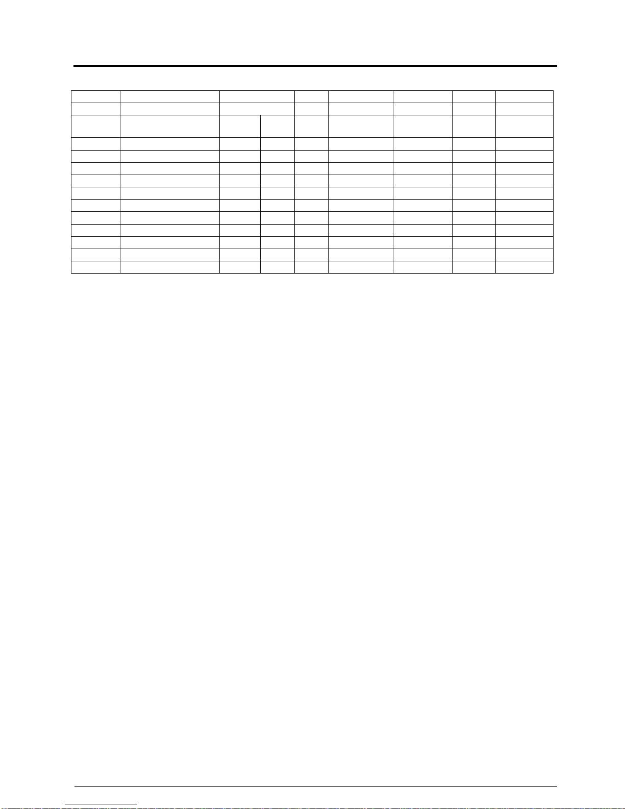
Capacité Type Vitesse Brins Chaîne Puissance In Id
Capacity Type Speed Falls Chain Power In Id
(kg) A m/min Ft /
min
KW A A
125 SM1 128M1-A 8 32 1 3,1 x 9,3 0.2 1.0 2.5
250 SM2 254 M1-A 4 16 1 4 X 12 0.2 1.0 2.5
250 SM5 254 M1-A 4 16 1 4,8 X 12,5 0.4 1.3 3.3
250 SM5 258 M1-A 8 32 1 4,8 X 12,5 0.8 2.6 9
500 SM5 504 M1-A 4 16 1 4,8 X 12,5 0.4 1.3 3.3
500 SM5 508 M1-A 8 32 1 4,8 X 12,5 0.8 2.6 9
500 SM10 516 M1-A 16 64 1 6,8 X 17,8 1.75 3.4 16
1000 SM10 1004 M1-A 4 16 1 6,8 X 17,8 0.9 2.3 11
1000 SM10 1008 M1-A 8 32 1 6,8 X 17,8 1.75 3.4 16
2000 SM10 2002 M1-A 2 8 2 6,8 X 17,8 0.9 2.3 11
2000 SM10 2004 M1-A 4 16 2 6,8 X 17,8 1.75 3.4 16
400Vac/50Hz values. – ft/min. at 60Hz.

STAGEMAKER® LINE
GUIDE TECHNIQUE
TECHNICAL GUIDE
Page 21
VERLINDE se réserve le droit de modifier sans préavis les caractéristiques de son matériel
VERLINDE reserve the right to modify or improve equipment described in this document
11/2008 VESAFR/GBSM04A
DETAILS TECHNIQUES
PALANS VERSION B
TECHNICAL DETAILS
HOISTS VERSION B
Caractéristiques standard :
• Palan livré avec chaîne noire (Sauf
SM16/20/25)
• Moteur de levage classe F
• Limiteur de couple
• Frein à disque
• Coffret électrique métallique (SM1 en
NORYL et SM16/25 en ABS)
• Peinture noire mat sur palan (RAL 7021)
• Crochets suspendus fixes
perpendiculaires
• Bac à chaîne plastique
• Commande basse tension 48 volts avec
contacteurs
• Alimentation triphasée 400V/50Hz ou
460V/60Hz
• Fin de course électrique haut et bas
standard (sauf SM2)
• Butée réglable de fin de course haut (sauf
SM2)
• Câbles de connexion et prise CE 4 pôles 16 Amp. (Type P 17)
• Prise de tension : mâle rouge,
Prise de commande : femelle jaune (sauf
SM16/20/25 : prise type multiconnecteurs).
Standard features :
• Hoist delivered with black lifting chain
(except SM16/20/25)
• Class F hoisting motor.
• Built-in torque limiter device.
• Disc brake.
• Steel plated electric cubicle (SM1 has
NORYL cubical, SM16/25 has ABS
cubicle)
• Non-reflecting matt black paint finish (RAL
7021)
• Fixed perpendicular suspension hook.
• Chain bucket
• Low voltage control with main contactor
48Vac
• Power supply3PH: 400V/50Hz, 460V/60Hz
• Standard upper / lower limit switches
(except SM2)
• Adjustable upper limit switch (except SM2)
• Connection cables with CE plugs 4p-
16Amp (Type P17).
• Power connector : male red
control connector : female yellow (except
SM16/20/25 : plug type multi connectors)
Options :
• Alimentation triphasée 230/50 ou 60Hz
(sauf SM25).
• Double frein pour SM5 et SM10 et
SM16/20/25.
• Protection thermique sur le moteur.
(standard sur SM25)
• Câble de connexion 0.5m avec prise type
harting 6P.
• Crochets rotatifs
• Option utilisation inversée (Guide chaîne
chainflux (SM5 et SM10), poignées de
transport, crochets rotatifs, pas de fin de
course électrique standard. Si
nécessaire prendre, en plus, l’option fin
de course à came
• Fin de courses à cames électrique (sauf
SM2)
• Crochet à fermeture automatique (SM05
et SM10)
Options :
• Power supply 3f-230Vac-50 or 60Hz
(except SM25).
• Double brake for SM5, SM10 and
SM16/20/25.
• Motor thermal protection (standard for
SM25).
• Connection cable 0.5m with type harting
plug 6P
• Swivelling upper and lower hooks
• Option for inverted use (flux chain guide
(SM5 and SM10), hand grips, swivelling
hooks, no standard electrical limit
switches. If necessary, take option
geared end limit switches)
• Electrical geared limit switches (except
SM2)
• Self locking hook (SM05 and SM10)

STAGEMAKER® LINE
GUIDE TECHNIQUE
TECHNICAL GUIDE
Page 22
VERLINDE se réserve le droit de modifier sans préavis les caractéristiques de son matériel
VERLINDE reserve the right to modify or improve equipment described in this document
11/2008 VESAFR/GBSM04A
• Capot pluie Stagemaker
• Coffret électrique métallique pour SM1
• Drain pour éviter que l’eau ne stagne au
niveau de la noix de levage (sauf SM1,
SM2 et SM16/25)
• Stagemaker textile rain cover
• Steel plated electric cubicle for SM1
• Drain hole to avoid water in load wheel
compartment (except SM1, SM2 and
SM16/25)
La version B peut être utilisée avec les
contrôleurs suivants : FL4PLV, FL8PLV,
FL12PLV, FL4PRMLV, FL8PRMLV,
FL12PRMLV, FL4PRMLVSR, FL8PRMLVSR
et FL12PRMLVSR.
Version B can be used with the following
controllers: FL4PLV, FL8PLV, FL12PLV,
FL4PRMLV, FL8PRMLV, FL12PRMLV,
FL4PRMLVSR, FL8PRMLVSR and
FL12PRMLVSR.
Options :
Les contrôleurs type « FLxPLV… » peuvent
en options être munis de prises type
« Harting » 6P+T à la place des connecteurs
2 x CE rouge/jaune
Options :
Controllers FL could be supplied with type
“Harting” 6 poles connector instead of 2 x CE
Red / Yellow plugs.
Schémas électriques :
SM1 : W1182111 SM5 : W1192111
SM10 : W1202111
SM16/20/25 : W1222111
Electrical drawings :
SM1 : W1182111 SM5 : W1192111
SM10 : W1202111
SM16/20/25 : W1222111
Capacité Type Vitesse Brins Chaîne Puissance In Id
Capacity Type Speed Falls Chain Power In Id
(kg)
B1 ou / or B2
m/min ft/min KW A A
125 SM1 128M1-B 8 32 1 3,1x9,3 0.2 1.0 2.5
250 SM2 254 M1-B 4 16 1 4X12 0.2 1.0 2.5
250 SM5 254 M1-B 4 16 1 4,8X12,5 0.4 1.3 3.3
250 SM5 258 M1-B 8 32 1 4,8X12,5 0.8 2.6 9
500 SM5 504 M1-B 4 16 1 4,8X12,5 0.4 1.3 3.3
500 SM5 508 M1-B 8 32 1 4,8X12,5 0.8 2.6 9
500 SM10 516 M1-B 16 64 1 6,8X17,8 1.75 3.4 16
1000 SM10 1004 M1-B 4 16 1 6,8X17,8 0.9 2.3 11
1000 SM10 1008 M1-B 8 32 1 6,8X17,8 1.75 3.4 16
1600 SM16 1608 M1-B 8 32 1 9X27 3.5 7.4 31
2000 SM10 2002 M1-B 2 8 2 6,8X17,8 0.9 2.3 11
2000 SM10 2004 M1-B 4 16 2 6,8X17,8 1.75 3.4 16
2000 SM20 2008 M1-B 8/2 32/8 1 11.3X31 3.5 7.4 31
2500 SM25 2506 M1-B 6.3/1.6 25/6 1 11.3X31 3.5 7.4 31
5000 SM25 5006 M1-B 3.2/0.75 12.5/3 2 11.3X31 3.5 7.4 31
400Vac/50Hz values– ft/min. at 60Hz.

STAGEMAKER® LINE
GUIDE TECHNIQUE
TECHNICAL GUIDE
Page 23
VERLINDE se réserve le droit de modifier sans préavis les caractéristiques de son matériel
VERLINDE reserve the right to modify or improve equipment described in this document
11/2008 VESAFR/GBSM04A
DETAILS TECHNIQUES
PALANS VERSION C
TECHNICAL DETAILS
HOISTS VERSION C
Caractéristiques standard :
• Palan livré avec chaîne noire
• Moteur de levage classe F
• Limiteur de couple
• Frein à disque
• Coffret électrique métallique (SM1 en
NORYL)
• Peinture noire mat sur palan (RAL 7021)
• Crochets suspendus fixes perpendiculaires
• Bac à chaîne plastique
• Commande basse tension 48 volts avec
contacteurs
• Alimentation triphasée 400V/50Hz ou
460V/60Hz
• Fin de course électrique haut et bas standard
• Butée réglable de fin de course haut
• Roulement codeur avec filtre pour les SM5 et
SM10. Codeur incrémental pour le SM1.
• Prise 16P+T métallique pour puissance et
commande.
Standard features :
• Hoist delivered with black lifting chain
• Class F hoisting motor.
• Built-in torque limiter device.
• Disc brake.
• Steel plated electric cubicle (SM1 has
NORYL cubical)
• Non-reflecting matt black paint finish (RAL
7021)
• Fixed perpendicular suspension hook.
• Chain bucket
• Low voltage control with main contactors
48Vac
• Power supply 3PH : 400V/50Hz,
460V/60Hz
• Standard upper / lower limit switches
• Adjustable upper limit switch
• Sensor bearing with filter for SM5 and
SM10. Incremental encoder for SM1.
• Special 16P+G metallic plug for control
and power.
Options :
• Alimentation triphasée 230/50 ou 60Hz.
• Double frein pour SM5 et SM10 uniquement.
• Protection thermique sur le moteur.
• Crochets rotatifs (sauf crochet supérieur
SM1)
• Option utilisation inversée (Guide chaîne
chainflux, poignées de transport, crochets
rotatifs et FDC électriques à cames (sauf sur
SM1, pas de fin de courses))
• Fin de courses à cames électrique (Sauf
SM1)
• Crochet à fermeture automatique (SM5 et
SM10)
• Capot pluie Stagemaker
• Drain au niveau de la noix de levage (sauf
SM1)
• Limiteur de charge électronique / détection
sous charge.
Options :
• Power supply 3f-230Vac-50 or 60Hz.
• Double brake for SM5 and SM10 only.
• Motor thermal protection.
• Swivelling hooks (except top hook on
SM1)
• Option for inverted use (flux chain guide,
hand grips, swivelling hooks and geared
limit switches (except SM1, no electrical
limit switches))
• Electrical geared limit switches (except
SM1)
• Self locking hook (SM5 and SM10)
• Stagemaker textile rain cover
• Drain hole to avoid water in load wheel
compartment. (except SM1)
• Electronic overload / under load detection.
Contrôleur pour palan version C : R8CPU-C1.
Version C can be used with controller :
R8CPU-C1 only.
Le codeur ou le roulement codeur délivre des
impulsions qui permettent au contrôleur CPU de
calculer la position de la charge par
programmation. Les positions ne sont pas
absolues ; elles ont besoin d’être remises à zéro
The encoder or the sensor bearing gives
pulses, which allow the CPU controller to
calculate the position of the load by
computing. Positions are not absolute and
need to be reset.

STAGEMAKER® LINE
GUIDE TECHNIQUE
TECHNICAL GUIDE
Page 24
VERLINDE se réserve le droit de modifier sans préavis les caractéristiques de son matériel
VERLINDE reserve the right to modify or improve equipment described in this document
11/2008 VESAFR/GBSM04A
Schémas électriques :
SM1 : W1182109
SM5 : W1192136
SM10 : W1202135
Electrical drawings :
SM1 : W1182109
SM5 : W1192136
SM10 : W1202135
Capacité Type Vitesse Brins Chaîne Puissance In Id
Capacity Type Speed Falls Chain Power In Id
(kg) C m/min ft/min KW A A
125 SM1 128M1-C 8 32 1 3,1x9,3 0.2 1.0 2.5
250 SM5 254M2-C 4 16 1 4.8x12.5 0.4 1.3 3.3
250 SM5 258M2-C 8 32 1 4.8x12.5 0.8 2.6 9
250 SM5 2516M1-C 16 64 1 4.8x12.5 0.8 2.6 9
500 SM5 504M1-C 4 16 1 4.8x12.5 0.4 1.3 3.3
500 SM5 508M1-C 8 32 1 4.8x12.5 0.8 2.6 9
500 SM10 516 M1-C 16 64 1 6,8X17,8 1.75 2.3 16
1000 SM10 1004 M1-C 4 16 1 6,8X17,8 0.9 2.3 11
1000 SM10 1008 M1-C 8 32 1 6,8X17,8 1.75 3.4 16
2000 SM10 2002 M1-C 2 8 2 6,8X17,8 0.9 2.3 11
2000 SM10 2004 M1-C 4 16 2 6,8X17,8 1.75 3.4 16
400Vac/50Hz values – ft/min. at 60Hz.

STAGEMAKER® LINE
GUIDE TECHNIQUE
TECHNICAL GUIDE
Page 25
VERLINDE se réserve le droit de modifier sans préavis les caractéristiques de son matériel
VERLINDE reserve the right to modify or improve equipment described in this document
11/2008 VESAFR/GBSM04A
DETAILS TECHNIQUES
PALANS VERSION D
TECHNICAL DETAILS
HOISTS VERSION D
Palan à la nome DIN 56950, dite BGV-C1
(avant VBG 70).
Caractéristiques standard :
• Palan livré avec chaîne noire
• Moteur de levage classe F
• Limiteur de couple
• Frein à disque
• Coffret électrique métallique
• Peinture noire mat sur palan (RAL 7021)
• Crochets suspendus fixes perpendiculaires
• Bac à chaîne plastique
• Commande basse tension 48 volts avec
contacteurs
• Alimentation triphasée 400V/50Hz
• 4 Fin de course électrique à cames
(mouvement + sécurité)
• Prise 16P+T métallique pour puissance et
commande.
• Relais de détection de surcharge
électronique.
• Double frein.
• Prise de diagnostique
Hoist in accordance with DIN 56950 or BGV-C1
(former VBG 70).
Standard features :
• Hoist delivered with black lifting chain
• Class F hoisting motor.
• Built-in torque limiter device.
• Disc brake.
• Steel plated electric cubicle
• Non-reflecting matt black paint finish (RAL
7021)
• Fixed perpendicular suspension hook.
• Chain bucket included
• Low voltage control with main contactor
48Vac
• Power supply3PH: 400V/50Hz
• 4 Geared limit switches (movement and
security)
• Special 16P+G metallic plug for control and
power.
• Electronic overload relay.
• Double brake.
• Diagnose plug
Options :
• Protection thermique sur le moteur
• Roulement codeur avec filtre (pour
application avec CPU)
• Boite de test
• Alimentation triphasée 230/50 ou 60Hz.
• Crochet à fermeture automatique
• Capot pluie Stagemaker
• Drain au niveau de la noix de levage
• Option utilisation inversée (Guide chaîne
chainflux, poignées de transport, crochets
rotatifs)
• Limiteur de charge électronique / détection
sous charge.
Options :
• Motor thermal protection.
• Sensor bearing with filter (for CPU
application)
• Diagnose test box
• Power supply 3f-230Vac-50 or 60Hz .
• Self locking hook
• Stagemaker textile rain cover
• Drain hole to avoid water in load wheel
compartment.
• Option for inverted use (polyamide chain
guide, hand grips, swivelling hooks)
• Electronic overload / under load detection.
Schémas électriques :
SM10 : W1202E30
Electrical drawing :
SM10 : W1202E30
Contrôleur pour palan version D : B_PRMLV-C1,
R_PRMLV-C1. Si équipé du roulement codeur :
RxCPU-VS
Controllers for Version D hoists: B_PRMLV-C1,
R_PRMLV-C1, and if equipped with a sensor
bearing: RxCPU-VS

STAGEMAKER® LINE
GUIDE TECHNIQUE
TECHNICAL GUIDE
Page 26
VERLINDE se réserve le droit de modifier sans préavis les caractéristiques de son matériel
VERLINDE reserve the right to modify or improve equipment described in this document
11/2008 VESAFR/GBSM04A
Important:
Le palan showbiz version D à la norme BGV-C1
ne peut pas être modifié et ne peut pas être
vendu sans appareillage. En effet une application
est dite BGC-C1 si elle répond mécaniquement
et électriquement à la norme DIN 56950.Celle-ci
s’applique aux palans et aux contrôles
également.
Warning:
The BGV-C1 hoist should not be modified and
should not be sold without electrical control
elements. An application is BGV-C1, only if it is
mechanically and electrically in accordance with
DIN 56950. This includes hoist as well as
controls.
Nota : Conformément à la norme BGV-C1, la
capacité du palan est déclassée de 50%,
l'embrayage restant réglé à pleine capacité afin
de respecter un facteur de sécurité mécanique
de 10.
Note: In line with the BGV-C1 regulations, the
hoist capacity is down rated with 50%,
however the clutch remains adjusted at full
rating in order to comply with the
mechanical safety factor of 10.
Exemple :
• SM10.1004. (1 tonne) réglage normal de
l'embrayage = 1250 Kg
• SM10.1004. déclassement BGV-C1 de 50%
à 500 kg (SM10.504..) réglage de
l'embrayage = 1400 kg Limiteur de charge
électrique réglé sur 600 kg.
Example :
• SM10.1004. (1 ton) standard clutch setting
= 1250 Kg
• SM10.1004. BGV-C1 50% down rated to
500 kg (SM10.504..) clutch setting = 1400
Kg. Electric overload setting at 600 Kg.
Coffret de test
Le coffret électrique du palan BGV-C1 est équipé
à l’intérieur d’une prise femelle spéciale
permettant le raccordement d’un coffret de test.
Ce coffret n’est pas vendu avec le palan. Il doit
être commandé spécialement. Faire une ligne de
commande séparée avec la référence suivante :
52293167.
Diagnose test box
The hoist control panel is equipped with a plug
to be connected to a diagnose test box. This
box is not sold with the hoist but optional
available for service stations. If required, it must
be inserted on the order as a separate line
referring to code: 52293167.
Fonction et utilisation :
Pour connecter ce coffret de test, le palan ne doit
pas avoir de charge. Ce coffret de test permet,
en effet, de contrôler un à un les fins de course à
cames, ainsi que de contrôler le bon
fonctionnement des freins, (frein principal et frein
de sécurité).
Function and utilisation :
Before using this facility read carefully the
instructions given in the user manual. This box
allows the service engineer to test one by one
the contacts of the geared limit switches, and
also the main and security brakes.
Attention, lors du contrôle de l’un de ces deux
freins à manque de courant, l’autre frein est
inhibé, c’est à dire qu’il ne retient plus la charge.
Schéma électrique : Z1202E01
Warning: During this test the brakes are one by
one disabled, so safety precautions should be
taken and only skilled personnel may perform
these tests.
Electrical drawing : Z1202E01
TB TA
0
S1 S2 S3 S4
TLS TEST
I 0 I 0 I 0 I 0
TB TA
0
S1 S2 S3 S4
TLS TEST
I 0 I 0 I 0 I 0

STAGEMAKER® LINE
GUIDE TECHNIQUE
TECHNICAL GUIDE
Page 27
VERLINDE se réserve le droit de modifier sans préavis les caractéristiques de son matériel
VERLINDE reserve the right to modify or improve equipment described in this document
11/2008 VESAFR/GBSM04A
Capacité Type Vitesse Brin Chaîne Puissance In Id
Capacity Type Speed Falls Chaine Power In Id
(kg) A m/min ft/min KW A A
125 SM5 124M1-D 4 32 1 4,8X12,5 0,85 1,6 8,3
125 SM5 128M1-D 8 32 1 4,8X12,5 0,85 1,6 8,3
250 SM5 254M1-D 4 32 1 4,8X12,5 0,85 1,6 8,3
250 SM5 258M1-D 8 32 1 4,8X12,5 0,85 1,6 8,3
250 SM10 516 M1-D 16 64 1 6,8X17,8 1.75 3.4 16
500 SM5 504M1-D 4 16 2 4,8X12,5 0,85 1,6 8,3
500 SM10 504 M1-D 4 16 1 6,8X17,8 0.9 2.3 11
500 SM10 508 M1-D 8 32 1 6,8X17,8 1.75 3.4 16
1000 SM10 1002 M1-D 2 8 2 6,8X17,8 0.9 2.3 11
1000 SM10 1004 M1-D 4 16 2 6,8X17,8 1.75 3.4 16
400Vac/50Hz values – ft/min. at 60Hz.

STAGEMAKER® LINE
GUIDE TECHNIQUE
TECHNICAL GUIDE
Page 28
VERLINDE se réserve le droit de modifier sans préavis les caractéristiques de son matériel
VERLINDE reserve the right to modify or improve equipment described in this document
11/2008 VESAFR/GBSM04A
DETAILS TECHNIQUES
PALANS VERSION E
TECHNICAL DETAILS
HOISTS VERSION E
Caractéristiques standard :
• Palan livré avec chaîne noire (sauf
SM16/20/25)
• Moteur de levage classe F
• Limiteur de couple
• Frein à disque
• Coffret électrique métallique
• Peinture noire mat sur palan (RAL 7021)
• Crochets suspendus fixes perpendiculaires
• Bac à chaîne plastique
• Alimentation triphasée 400V/50Hz ou
460V/60Hz
• Fin de course électrique haut et bas
standard
• Butée réglable de fin de course haut.
• Sans câble ni prise.
Standard features :
• Hoist delivered with black lifting chain
(except SM16/20/25)
• Class F hoisting motor.
• Built-in torque limiter device.
• Disc brake.
• Steel plated electric cubicle
• Non-reflecting matt black paint finish (RAL
7021)
• Fixed perpendicular suspension hook.
• Chain bucket included for 30m of chain.
• Power supply3PH: 400V/50Hz, 460V/60Hz
• Standard upper / lower limit switches
• Adjustable upper limit switch.
• Without connection cable, plug or cable
gland
Options :
• Alimentation triphasée 230/50 ou 60Hz
• Double frein
• Protection thermique sur le moteur.
• Crochets rotatifs
• Option utilisation inversée (Guide chaîne
Chainflux, poignées de transport, crochets
rotatifs et FDC électriques à cames)
• Crochet à fermeture automatique
• Capot pluie Stagemaker
• Drain au niveau de la noix de levage
• Roulement codeur ou codeur avec filtre
• Limiteur de charge électronique / détection
sous charge.
• Fin de course à cames électrique
Options :
• Power supply 3f-230Vac-50 or 60Hz
• Double brake
• Motor thermal protection.
• Swivelling upper and lower hooks
• Option for inverted use (Flux chain guide,
hand grips, swivelling hooks (except top
hook on SM1) and geared limit switches)
• Self locking hook
• Stagemaker textile rain cover
• Drain hole to avoid water in load wheel
compartment
• Sensor bearing or encoder with filter
• Electronic overload / under load detection.
• Electrical geared limit switches
Schéma électrique : W1202E107
Electrical drawing: W1202E107
Ces modèles sont conçus pour une utilisation
avec un variateur de vitesse hors de notre
fourniture.
This version has been designed to be used
with inverter which is no part of our supply.

STAGEMAKER® LINE
GUIDE TECHNIQUE
TECHNICAL GUIDE
Page 29
VERLINDE se réserve le droit de modifier sans préavis les caractéristiques de son matériel
VERLINDE reserve the right to modify or improve equipment described in this document
11/2008 VESAFR/GBSM04A
Capacité Type Vitesse Brins Chaîne Puissance In Id
Capacity Type Speed Falls Chain Power In Id
(kg) E m/min Ft /min KW A A
250 SM5 254M2-E 4 16 1 4.8x12.5 0.4 1.3 3.3
250 SM5 258M2-E 8 32 1 4.8x12.5 0.8 2.6 9
250 SM5 2516M1-E 16 64 1 4.8x12.5 0.8 2.6 9
500 SM5 504M1-E 4 16 1 4.8x12.5 0.4 1.3 3.3
500 SM5 508M1-E 8 32 1 4.8x12.5 0.8 2.6 9
500 SM10 516 M1-E 16 64 1 6,8X17,8 1.75 3.4 16
1000 SM10 1004 M1-E 4 16 1 6,8X17,8 0.9 2.3 11
1000 SM10 1008 M1-E 8 32 1 6,8X17,8 1.75 3.4 16
2000 SM10 2002 M1-E 2 8 2 6,8X17,8 0.9 2.3 11
2000 SM10 2004 M1-E 4 16 2 6,8X17,8 1.75 3.4 16
2000 SM20 2008B1-E 8/2 32/8 1 11.3x31 3.5/0.9 7.4/3.7 31/8.3
2500 SM25 2506B1-E 6.3/1.6 25/6 1 11.3x31 3.5/0.9 7.4/3.7 31/8.3
5000 SM25 5003B1-E 3.25/0.8 12.5/3 2 11.3x31 3.5/0.9 7.4/3.7 31/8.3
400Vac/50Hz values – ft/min. at 60Hz.
Capacité Type Vitesse Moteur
Motor
Reduction
carter
Capacity Type Speed
Poles Rpm
Gear ratio
(kg) E m/min ft/min Poles Tr/min
250 SM5 254M2-E 4 16 4 1390 43.19
250 SM5 258M2-E 8 32 2 2780 43.19
250 SM5 2516M1-E 16 64 2 2780 21.29
500 SM5 504M1-E 4 16 4 1390 43.19
500 SM5 508M1-E 8 32 2 2780 43.19
500 SM10 516 M1-E 16 64 2 2780 31.9
1000 SM10 1004 M1-E 4 16 4 1390 58.3
1000 SM10 1008 M1-E 8 32 2 2780 58.3
2000 SM10 2002 M1-E 2 8 4 1390 58.3
2000 SM10 2004 M1-E 4 16 2 2790 58.3
2000 SM20 2008B1-E 8/2 32/8 2/8 2710/635 112.99
2500 SM25 2506B1-E 6.3/1.6 25/6 2/8 2710/635 144.16
5000 SM25 5003B1-E 3.25/0.8 12.5/3 2/8 2710/635 144.16
400Vac/50Hz values – ft/min. at 60Hz.

STAGEMAKER® LINE
GUIDE TECHNIQUE
TECHNICAL GUIDE
Page 30
VERLINDE se réserve le droit de modifier sans préavis les caractéristiques de son matériel
VERLINDE reserve the right to modify or improve equipment described in this document
11/2008 VESAFR/GBSM04A
DETAILS TECHNIQUES
PALANS VERSION V
TECHNICAL DETAILS
HOISTS VERSION V
Caractéristiques standard :
• Position normale
• Alimentation 3x380 à 480V-50Hz.
• Basse tension 48Vac avec contacteur
principal
• Palan livré avec chaîne noire
• Moteur de levage classe F
• Limiteur de couple
• Frein à disque
• Variateur intégré
• Fin de course électrique haut et bas
standard
• Butée réglable de fin de course haut
• Détection de survitesse
• Prise 16P+T métallique pour puissance et
commande
• Bac à chaîne SM
• Protection thermique des moteurs
• Peinture noire mat sur palan (RAL 7021)
• Crochets suspendu fixe perpendiculaire
• Coffret électrique métallique variation
• Mode de contrôle AU
• Poignées de transport
• Roulement codeur avec filtre
Standard features :
• Normal position
• Power supply 3x 380 to 480Vac-50Hz.
• Low voltage control with main contactor
48Vac
• Black chain.
• Class F hoisting motor.
• Built-in torque limiter device.
• Disc brake.
• Built-in inverter drive
• Standard upper / lower limit switches
• Adjustable upper limit switch
• Overspeed detection
• Special 16P+G metallic plug for control
and power.
• SM chain bag.
• Motor thermal protection.
• Non-reflecting matt black paint finish (RAL
7021)
•
Fixed perpendicular suspension hook.
• Steel plated electric cubicle for inverter
• Control mode AU
• hand grips
• Sensor bearing with filter
Options :
• Double frein
• Crochets rotatifs
• Option utilisation inversée (inclus Guide
chaîne ChainFlux, poignées de transport,
crochets rotatifs, fin de courses à cames)
• Fin de courses à cames électrique
• Crochet à fermeture automatique
• Capot pluie Stagemaker
• Drain au niveau de la noix de levage
Options :
• Double brake
• Swivelling hooks
• Option for inverted use (include flux chain
guide, hand grips, swivelling hooks and
geared limit switches)
• Geared limit switches
• Self locking hook
• Stagemaker textile rain cover
•
Drain hole to avoid water in load wheel
compartment.
Contrôleur pour palan version V :
- RxxPRM-VS
- R8CPU-VS
Controller fot Hoist version V :
- RxxPRM-VS
- R8CPU-VS
Schéma électrique : W1202107
Electrical drawing: W1202107
Capacité Type Vitesse Brins Chaîne Puissance
Capacity Type Speed Falls Chain Power
(kg) V m/min ft/min KW
500 SM10 508 V2-V 0.5=>8 2=>32 1 6,8X17,8 1.8
500 SM10 516 V1-V 1=>16 4=>64 1 6,8X17,8 1.8
1000 SM10 1008 V1-V 0.5=>8 2=>32 1 6,8X17,8 1.8
2000 SM10 2004 V1-V 0.25=>4 1=>16 2 6,8X17,8 1.8
400Vac /60Hz values

STAGEMAKER® LINE
GUIDE TECHNIQUE
TECHNICAL GUIDE
Page 31
VERLINDE se réserve le droit de modifier sans préavis les caractéristiques de son matériel
VERLINDE reserve the right to modify or improve equipment described in this document
11/2008 VESAFR/GBSM04A
DETAILS TECHNIQUES
PALANS VERSION S
TECHNICAL DETAILS
HOISTS VERSION S
Caractéristiques standard : Standard features :
• Palan livré avec chaîne noire
• Moteur de levage classe F
• Limiteur de couple
• Frein à disque
• Alimentation monophasée 230Vac-
50/60Hz.
• Basse tension 48 Vac avec contacteurs
• Câbles de connexion 0,50 m avec prise
type harting 6P pour la commande
• Capacité pour démarrage et
fonctionnement
• Borniers pour connections électriques
• Bac à chaîne plastique
• Coffret électrique métallique
• Position normale
• Boite a boutons avec marche / arrêt
• Peinture noire mat sur palan (RAL 7021)
• Crochets suspendus fixes
perpendiculaires
• Hoist delivered with black lifting chain
• Class F hoisting motor.
• Built-in torque limiter device.
• Disc brake.
• Power supply single phase 230Vac-
50/60Hz.
• Low voltage control with contactors 48 Vac
• Connection cable 0,50 m with harting type
plug 6P, control only
• Starting and running capacitor
• Terminals for power connection
• Standard chain bag. (12m)
• Steel plated cubicle
• Normal position
• Button-box with E-stop
• Non-reflecting matt black paint finish (RAL
7021)
• Fixed perpendicular suspension hook.
Options :
- Sur demande, version inversée
Options :
- On request, inverted position
Pour les palans version S, les contrôleurs
doivent faire l’objet d’une demande
spéciale.
For hoists version S, controllers are on
demand.
Schéma électrique :
SM5 : W1197133
Electrical drawing :
SM5 : W1197133
Capacité Type Vitesse Brins Chaîne Puissance In Id
Capacity Type Speed Falls Chain Power In Id
(kg) A m/min ft/min KW A A
80 SM1 084M1-S 4 16 1 3,1x9,3 0,1 1.5 2.25
125 SM1 124M1-S 4 16 1 3,1x9,3 0,1 1.5 2.25
250 SM1 252M1-S 2 8 2 3,1x9,3 0.1 1.5 2.25
250 SM5 254M1-S 4 16 1 4,8X12,5 0,4 5 7.2
500 SM5 504M1-S 4 16 1 4,8X12,5 0,4 5 7.2
1000 SM5 1002M1-S 2 8 2 4,8X12,5 0.4 5 7.2
230Vac/50Hz values – ft/min. at 60Hz.

STAGEMAKER® LINE
GUIDE TECHNIQUE
TECHNICAL GUIDE
Page 32
VERLINDE se réserve le droit de modifier sans préavis les caractéristiques de son matériel
VERLINDE reserve the right to modify or improve equipment described in this document
11/2008 VESAFR/GBSM04A
POINTS A PRENDRE
EN CONSIDERATION
POINTS
TO OBSERVE
1) Alimentation :
400 V - tri. - 50 Hz / frein = 190 V c.c.
230 V - tri.- 50 Hz / frein = 97 c.c.
Autres tensions, notamment doubles
tensions, sur demande.
1) Power supply:
400 volt - 3f - 50 Hz. / brake = 190 Vdc
230 volt - 3f - 50 Hz. / brake = 97 Vdc
Other voltages, including dual voltages on
demand.
2) La chute de tension maximale sur les
bornes du palan (moteur) est de 5%
conformément à EN 60-204.
La longueur de câble à respecter est
indiquée dans les tableaux.
2) Maximum voltage drop on hoist (motor)
terminals is 5% according to EN 60-204.
Cable length to be respected as given in
tables.
Note :
Ne pas dépasser la longueur de câble
indiquée dans le tableau, cela peut
entraîner un comportement imprévu de
l'installation et provoquer des accidents ou
sérieusement endommager le matériel ou
même blesser le personnel.
Note :
Don’t exceed cable length as listed in the
table, it might cause unexpected behaviour
of the installation and could lead to
accidents or severe damage of the
equipment or even personnel.
3) Pour les palans à variateur de vitesse (E),
la fréquence maximale est de 60 Hz pour
les moteurs bipolaires (3000 t/m) et 75 Hz
pour les moteurs quadripolaires (1500 t/m).
Dans ces cas, les freins doivent être
actionnés par des contacteurs distincts
câblés comme indiqué sur le plan en
annexe.
3) For inverter controlled hoists (E), the
maximum frequency is 60 Hz in case of 2
pole motors (3000 rpm) and 75 Hz for 4
pole motors (1500 rpm). In these cases the
brakes must be activated by separate brake
contactors, wired in accordance to drawing
4) Protéger le palan contre les intempéries
avec une protection adéquate. Bien que le
palan ait été conçu pour être utilisé à
l'extérieur, une exposition continue à des
conditions climatiques sévères peut
endommager les composants électriques.
4) Protect the hoist in outdoor applications
using a sufficient cover. Although the hoist
is designed for open-air use, still
continuously exposure extreme weather
conditions might lead to damage of electric
components.
5) La température ambiante maximale à
respecter est de 40˚C. Les appareils
dégageant de la chaleur et se trouvant à
proximité du palan, lampes ou appareils de
chauffage par exemple, devront être réglés
de façon à ne pas affecter la température
du palan.
5) The maximum ambient temperature to be
respected is 40 ˚C. Heat generating
elements in the vicinity of the hoist e.g.
lamps, heaters etc. must be adjusted in a
way that the hoist temperature won’t be
effect.

STAGEMAKER® LINE
GUIDE TECHNIQUE
TECHNICAL GUIDE
Page 33
VERLINDE se réserve le droit de modifier sans préavis les caractéristiques de son matériel
VERLINDE reserve the right to modify or improve equipment described in this document
11/2008 VESAFR/GBSM04A
6) Les palans ne doivent être soumis à
aucune obstruction, les crochets supérieur
et inférieur doivent être alignés.
6) Hoists should be free of any obstruction,
top and bottom hook must be in line.
BIEN MAUVAIS GOOD FAULT
7) Utiliser des palans SM10 à un brin pour
supports de structures afin de réduire
l'usure de la chaîne et les risques de
vrillage. Les roues doivent avoir des
enroulements adaptés et un diamètre
correct.
7) Use single fall SM10 hoists for ground
supports. It reduces chain wear and risk of
chain twisting. Wheels must have matching
groves and proper diameter.
8) Câbles d'alimentation :
Tous les contrôleurs exigent une
alimentation triphasée + neutre + terre.
Sections de câble alimentation triphasée
400 V :
commandes à 4 canaux 5 x 2,5 mm
2
(16 Amp)
commandes à 8 canaux 5 x 4 mm
2
(32 Amp)
8) Power supply cables:
All controllers require 3f + neutral + earth.
Cable sections at 400v-3f power supply:
4 channel controllers 5 x 2,5 mm
2
(16 Amp)
8 channel controllers 5 x 4 mm
2
(32 Amp)
Sections de câble intermédiaires alimentation
triphasée 400 V (câbles moteur) :
•
commandes à 4 canaux 4 x 1,5
or 2,5 mm2
•
commandes à 8 canaux 17 x 1,5
or 2,5 mm
2
Intermediary cable sections at 400v-3f power
supply (motor cables)
•
4 channel controllers 4 x 1,5 or 2,5 mm
2
•
8 channel controllers 17 x 1,5 or 2,5 mm
2
Voir la longueur maximale des câbles dans le
tableau de la page 41.
For maximum cable length see table on page
41

STAGEMAKER® LINE
GUIDE TECHNIQUE
TECHNICAL GUIDE
Page 34
VERLINDE se réserve le droit de modifier sans préavis les caractéristiques de son matériel
VERLINDE reserve the right to modify or improve equipment described in this document
11/2008 VESAFR/GBSM04A
CONTROLEURS
CONTROLLERS
La gamme de produits STAGEMAKER
comprend toute une série de commandes
conçues pour les multiples applications
courantes et pour les tournées.
STAGEMAKER product line includes a full
range of controllers, designed for the typical
multiple use and on on-tour applications.
Cette gamme comprend :
• Commandes pour palans à commande
directe, version A
- palans uniques
- commande par groupe de 4 palans
- commande par groupe de 8 palans
- commande par groupe de 12 palans
The range comprises off :
• Controllers for direct controlled hoists,
version A
- single hoists
- group control of 4 hoists
- group control of 8 hoists
- group control of 12 hoists
• Commandes pour palans à commande
très basse tension version B
- palans uniques
- commande par groupe de 4 palans
- commande par groupe de 8 palans
- commande par groupe de 12 palans
• Controllers for low voltage controlled
hoists version B
- single hoists
- group control of 4 hoists
- group control of 8 hoists
- group control of 12 hoists
• Commandes pour palans
programmables, version C et V ou
version D avec roulement codeur
- commande par groupe de 4 palans
- commande par groupe de 8 palans
• Controllers for programmable hoists,
version C and V or version D with
bearing sensor option
- group control of 4 hoists
- group control of 8 hoists
• Commandes pour palans VBG-C1,
version D
- palans uniques
- commande par groupe de 2 palans
- commande par groupe de 4 palans
- commande par groupe de 8 palans
- commande par groupe de 12 palans
• Controllers for VBG-C1 hoists, version
D
- single hoists
- group control of 2 hoists
- group control of 4 hoists
- group control of 8 hoists
- group control of 12 hoists
• Commandes pour palans version V non
programmable
- commande par groupe de 4 palans
- commande par groupe de 8 palans
- commande par groupe de 12 palans
• Controllers for hoists version V not
programmable
- group control of 4 hoists
- group control of 8 hoists
- group control of 12 hoists
Note :
Toutes les commandes mentionnées sont
destinées aux palans SM1 – SM2 – SM5 et
SM10, jusqu'à 1,8 kW en 400Vac et 0.9kW en
230 Vac.
Note:
All mentioned controllers are for SM1 – SM2 –
SM5 and SM10 up to 1.8 kW in 400Vac and
0.9kW in 230Vac
Commandes sur demande :
- Contrôleurs palans SM16 / 25
- Contrôleurs palans type S
- Contrôleurs avec prises spéciales
Controllers on demand :
- For Sm16 / 25
- For hoist type S
- With special plugs

STAGEMAKER® LINE
GUIDE TECHNIQUE
TECHNICAL GUIDE
Page 35
VERLINDE se réserve le droit de modifier sans préavis les caractéristiques de son matériel
VERLINDE reserve the right to modify or improve equipment described in this document
11/2008 VESAFR/GBSM04A
CONTROLEURS POUR PALAN
VERSION A
COMMANDE TENSION DIRECTE
CONTROLLERS FOR DIRECT
CONTROLLED HOIST VERSION A
COMMANDE UNIQUE (boîtier jaune)
Ces commandes sont fournies avec des
connecteurs CE M/FM montés sur câble de
0,5m. Elles doivent être installées entre le
câble de puissance et le connecteur du palan.
Il en existe deux modèles :
• commande pour un seul palan
• commande pour deux palans
SINGLE CONTROL (yellow box)
These controllers are supplied with CE
connectors M/FM fitted on 0,5m cable. It has
to be located between the power cable and
the hoist connector.
There are two models :
• controller for one single hoist
• controller for two hoists
Caractéristiques :
- commande directe version A
- la commande pour deux palans a des
boutons distincts pour la montée et la
descente
- boutons de montée et descente, action
directe
- puissance maximale 1,8 kW
- pas de présélection
- bouton d'arrêt d'urgence
Specifications :
- direct control version A
- controller for two hoists has separate
up/down buttons
- up and down buttons, direct action
- maximum power 1.8 kW
- no pre-selection
- emergency button
Controller for one hoist
Controller for two hoists

STAGEMAKER® LINE
GUIDE TECHNIQUE
TECHNICAL GUIDE
Page 36
VERLINDE se réserve le droit de modifier sans préavis les caractéristiques de son matériel
VERLINDE reserve the right to modify or improve equipment described in this document
11/2008 VESAFR/GBSM04A
COMMANDE PAR GROUPE
Les commandes permettant de commander
plusieurs palans simultanément sont intégrées
dans une flight case. Les commandes
économiques à 4 et 8 canaux du type SC4P &
SC8P sont intégrées dans une mallette en
ABS robuste. Les autres modèles, R4P - R8P
et R12P à 4, 8 ou 12 canaux, sont intégrés
dans un rack de 19 pouces (format 3U ou 6U),
avec flight case. Si l’appellation du contrôleur
est suivie de RM, il s’agit d’un contrôleur avec
une commande déportée (10m de câble). Si
l’appellation du contrôleur est suivie de
RMSR, il s’agit d’une commande déportée par
radio.
CONTROL GROUP
Controllers for group control are supplied in a
flight case. The economical 4 and 8 channel
controllers type SC4P & SC8P are built in a
solid ABS briefcase. The other models ; R4P R8P and R12P, 4 – 8 or 12 channel
controllers are of 19 Inch rack 3U or 6U
format, with flight case. If the designation of
the controller is followed by RM, the controller
is provided with remote. If the designation of
the controller is followed by RMSR, the
controller is provided with a radio remote.
Caractéristiques :
• Commande directe version A
• Un seul palan jusqu'à 1,8 kW par canal
400V / 3PH
• Un seul palan jusqu'à 0,9 kW par canal
230V / 3PH
• Deux palans avec coffret de distribution
intermédiaire CE (jusqu'à 1,8 kW par canal
en 400V / 3PH)
• Correction de niveau individuelle
• Présélection par canal (sélection par
groupe)
• Bouton « GO » qui active tous les canaux
sélectionnés
• Connexion des palans :
SCxx = prises CE P17, 4 pôles, rouges
Rxx = prises type harting 16 pôles (1 pour
4 palans.
• Bouton d'arrêt d'urgence
• Fonction maître-esclave pour 2
contrôleurs maximum (tous modèles)
• Sélection des composants selon groupe II
/ AC3
• Puissance absorbée par le moteur :
- 4 or 8 x 1,8 kW, alimentation triphasée
400 V.
- 4 or 8 x 0,9 kW alimentation triphasée
230 V.
• Protection contre les courts-circuits : une
fois à 10 kAmp maxi.
• Dispositif d'inversion de phase sur douille
d'entrée CE
Specifications :
• Direct control version A
• Single hoist up to 1.8 kW per channel (at
400v-3f)
• Single hoist up to 0.9 kW per channel (at
230v-3f)
• Two hoists with intermediary CE splitter
(up to 1.8kW per channel at 400v-3f)
• Individual level correction
• Pre-selection per channel (group
selection)
• One GO button effective on all selected
channels
• Hoist connections :
SCxx = type CE 4p red plugs
Rxx = type harting 16p (1 for each 4
hoists)
• Emergency stop
• Master-slave function for 2 controllers
maximum (all models)
• Component selection in accordance. with
group II / AC3
• Connected motor power:
- 4 or 8 x 1.8 kW at 400v-3f
- 4 or 8 x 0.9 kW at 230v-3f
• Short circuit proofing: once at max. 10
kAmp:
• Phase inversion facility on incoming CE
plug
Avec ce type de commande, la configuration
du palan doit être celle de la version A
Documents disponibles : Manuel d'utilisation
avec schémas électriques
Hoist configuration for this type of control
should be in accordance to version A
Available documents : Owners manual with
electrical diagrams

STAGEMAKER® LINE
GUIDE TECHNIQUE
TECHNICAL GUIDE
Page 37
VERLINDE se réserve le droit de modifier sans préavis les caractéristiques de son matériel
VERLINDE reserve the right to modify or improve equipment described in this document
11/2008 VESAFR/GBSM04A
Commande R8PRM à 8 canaux
8 channels controller R8PRM
Commande SC4P 4 canaux
4 channesl controler SC4P
MOTOR 4MOTOR 3
MOTOR 2
000
0
MOTOR 1
MARCHE
START
MOTOR 2MOTOR 1
MOTOR 4MOTOR 3
VERLI NDE

STAGEMAKER® LINE
GUIDE TECHNIQUE
TECHNICAL GUIDE
Page 38
VERLINDE se réserve le droit de modifier sans préavis les caractéristiques de son matériel
VERLINDE reserve the right to modify or improve equipment described in this document
11/2008 VESAFR/GBSM04A
CONTROLEURS POUR PALAN
VERSION B (COMMANDE BASSE
TENSION 48 VOLTS)
CONTROLLERS FOR 48 VOLT
CONTROLLED HOISTS
VERSION B
COMMANDE PAR GROUPE
Ces commandes sont intégrées dans un
coffret métallique à montage mural ou dans
une flight case en contre-plaqué.
GROUPE CONTROL
These controllers are mounted steel cabinet or
play-wood flight case.
Dans la configuration de base, un groupe de
relais permet un raccordement sans potentiel
des circuits de basse tension de chaque
palan.
The basic set-up is a configuration in which a
group of relays ensures a potential free
connection of the individual hoist low voltage
circuits.
Le nombre de canaux dépend des besoins.
Les fonctions de commande sont sur le coffret
ou sur le boîtier de commande à distance
muni d'une rallonge.
Number of channels is related to the
requirement.
The control functions are on the controller
cabinet or on a remote handheld with
extension cable.
Avec ce type de commande, la configuration
du palan doit être celle de la version B avec
ou sans contacts de fin de course électriques .
Sur toutes ces commandes les connexions se
trouvent à l'arrière sauf pour la commande
déportée. Ces commandes peuvent être
utilisées pour des applications fixes aussi bien
qu'en tournée.
Hoist configuration for this type of control
should be in accordance to version B with or
without electric limit switches.
These controllers have all connections in the
back except for the remote. They could be
used for fixed applications as well as on tour.
Disponibles :
FL4PLV, FL8PLV et FL12PLV sans
commande à distance,
FL4PRMLV, FL8PRMLV et FL12PRMLV avec
commande à distance.
FL4PRMLVSR, FL8PRMLVSR et
FL12PRMLVSR avec radiocommande.
Available are
:
FL4PLV, FL8PLV and FL12PLV all without
remote,
FL4PRMLV,FL8PRMLV , FL12PRMLV with
remote.
FL4PRMLVSR,FL8PRMLVSR ,
FL12PRMLVSR with radio remote
Caractéristiques :
• Basse tension directe version B
• Un seul palan jusqu'à 1,8 kW par canal
(alimentation triphasée 400 V)
• Un seul palan jusqu'à 0,9 kW par canal
(alimentation triphasée 230 V)
• Correction de niveau individuelle
• Présélection par canal (sélection par
groupe)
• Bouton « GO » qui active tous les canaux
sélectionnés
• Connexion des palans :
- Alimentation = CE P17, 4 pôles, rouges
- Commande = CE P17, 4 pôles, jaunes
• Bouton d'arrêt d'urgence
• Fonction maître / esclave pour 2
contrôleurs maximum (tous modèles)
• Sélection des composants selon groupe II
/ AC3.
Specifications :
• Direct low voltage version B
• Single hoist up to 1.8 kW per channel (at
400v-3f)
• Single hoist up to 0.9 kW per channel (at
230v-3f)
• Individual level correction
• Pre-selection per channel (group
selection)
• One GO button effective on all selected
channels
• Hoist connection :
- Power = All type CE, 4p, red plug female
- Control = All type CE, 4p, yellow plug male
• Emergency stop
• Master / slave function for 2 hoists
maximum ( all models)
• Component selection in accordance. with
group II / AC3

STAGEMAKER® LINE
GUIDE TECHNIQUE
TECHNICAL GUIDE
Page 39
VERLINDE se réserve le droit de modifier sans préavis les caractéristiques de son matériel
VERLINDE reserve the right to modify or improve equipment described in this document
11/2008 VESAFR/GBSM04A
• Puissance absorbée par le moteur :
- 4 ou 8 x 1.8 kW, alimentation triphasée
400 V
- 4 ou 8 x 0.9 kW, alimentation triphasée
230 V
• Protection contre les courts-circuits : une
fois à 10 kAmp maxi.
• Dispositif d'inversion de phase sur douille
d'entrée CE
• Connected motor power:
- 4 or 8 x 1.8 kW at 400v-3f
- 4 or 8 x 0.9 kW at 230v-3f
• Short circuit proofing: once at max. 10
kAmp:
• Phase inversion facility on incoming CE
plug
Option :
Connexion des palans avec une prise type
« harting » 6 pôles + terre (1 par palan)
Option :
Hoist connection through harting 6 p female (1
for each hoist)
Coffrets personnalisés :
Commande de spectacle pour 24 palans avec
course électrique.
Groupes présélectionnés commandés par
deux platines légères au niveau de la scène,
et commande de palan individuel à partir d'un
MCP au niveau du gril (+22 m) au moyen d'un
contrôleur programmable à affichage
numérique.
Tailor made panels :
Theatrical appliance for 24 hoists with electric
travel.
Pre-selected groups controlled by two light
weight panels at stage level, and individual
hoist control from MCP at grid level (+22 Mtr.)
by means of PLC with digital display.
Commandes à distance scénique Coffret électrique principal
Stage remote control Master control panel (MCP)
ESC
ENTER
SHIFT
SIEMENS
TD200
MOTOR - LT1 - N° 1
0
I
Off
On
DIRECT
CONTROL
REMOTE
CONTROL
type TF51PRM
VERLINDE
MOTOR
AL-3AL-2AL-1 AL-4
LT-3LT-2LT -1
AR-3AR-2AR-1 AR-4
GP-1PL-2PL-1
type FL8PRM
MOTOR 5-8
CONTROL
MOTOR 1-4
GENERAL
Telemecanique
OFF
STOP START
1.6
1.4
1.2
1
Test
Telemecanique
OFF
STOPSTART
1.6
1.4
1.2
1
Test
I/O START
48VAC
CONTROL
LIGHT
CONTROL
MOTOR
1 - 4
PLUG
MOTOR
5 - 8
AR
AV
.3
.1
.4
.2
.3
.1
.4
.2
NORMAL
INVERSE
PHASE
FAILURE
CEE
16-6h
3P+PE IP44
PLUG
3x400V+N+T
FUSE
VERLINDE
LIFTING EQUIPMENT
PG21
P
G
2
1
VERLINDE
LIFTING EQUIPMENT
MOTOR 2MOTOR 3MOTOR 4
MOTOR 8MOTOR 7MOTOR 6MOTOR 5
START
MOTOR 1
CEE
16-6h
3P+PE IP44
CEE
16-6h
3P+PE IP44
CEE
16-6h
3P+PE IP44
CEE
16-6h
3P+PE IP44
MOTOR 3MOTOR 2
MOTOR 1
MOTOR 4
CEE
16-6h
3P+PE IP44
CEE
16-6h
3P+PE IP44
CEE
16-6h
3P+PE IP44
CEE
16-6h
3P+PE IP44
MOTOR 1
MOTOR 2 MOTOR 3 MOTOR 4
CEE
16-6h
3P+PE IP44
CEE
16-6h
3P+PE IP44
CEE
16-6h
3P+PE IP44
CEE
16-6h
3P+PE IP44
MOTOR 7MOTOR 6
MOTOR 5
MOTOR 8
CEE
16-6h
3P+PE IP44
CEE
16-6h
3P+PE IP44
CEE
16-6h
3P+PE IP44
CEE
16-6h
3P+PE IP44
MOTOR 5
MOTOR 6 MOTOR 7 MOTOR 8

STAGEMAKER® LINE
GUIDE TECHNIQUE
TECHNICAL GUIDE
Page 40
VERLINDE se réserve le droit de modifier sans préavis les caractéristiques de son matériel
VERLINDE reserve the right to modify or improve equipment described in this document
11/2008 VESAFR/GBSM04A
CONTROLEURS
PROGRAMMABLES
VERSION C, V et D
CONTROLLERS FOR
PROGRAMMABLE PRESETS
VERSION C, V and D
Ces contrôleurs ont été spécialement conçus
pour être utilisés avec des palans équipés de
codeurs. Ils permettent un positionnement
précis et un total contrôle.
These controllers are specifically designed to
be used in conjunction with hoists equipped
with an encoder to enable position definition
and control
Les commandes sont intégrées dans un rack
de 19 pouces.
The controllers are built in a 19 inch-rack.
Controleur disponible en 8 canaux
Controller available is an 8 channels modular
systems
Commande programmable R8CPU-VS
/ R8CPU-VS Programmable controller
Caractéristiques :
• Commande très basse tension version C –
D et V
• Un seul palan jusqu'à 1,8 Kw par canal
(alimentation triphasée 400 V)
• Sélecteurs de montée/descente propres à
chaque canal
• Bouton « GO » qui active tous les canaux
sélectionnés
• Bouton d'arrêt d'urgence (à distance)
• Fonction maître-esclave jusqu'à 8 unités
(64 palans)
• Logiciel gratuit sur Internet*
• Programmation individuelle ou par groupe
• Fonctionnement simultané, avec ou sans
synchronisation
• Positionnement précis au moyen d'un
détecteur d'impulsions
• Programmation de mouvement de groupe
sur base de vitesse ou de temps (pour
version V uniquement)
• Mode : par « scène » ou « enchaînement
de scènes »
• Connexion des palans à un câble (16
broches)
• Détection de coupure de phase
• Dispositif d'inversion de phase sur douille
d'entrée CE
Specification :
• Low voltage control version C – D and V
• Single hoist up to 1.8 Kw per channel (at
400v-3f)
• Up and down selection per channel
• One GO button effective on all selected
channels
• Emergency stop (remote)
• Master-slave function up to 8 units (64
hoists)
• Software free of charge on Internet*
• Single, or group wise programming
• Simultaneously, synchronised or none
• Accurate positioning trough pulse sensor
• Speed based or time based Cue
definitions (for hoists version V only)
• Standard or effect mode function
• Hoist connections : harting 16 p (1 for
each hoist)
• Phase failure detection
• Phase inversion facility on incoming CE
plug

STAGEMAKER® LINE
GUIDE TECHNIQUE
TECHNICAL GUIDE
Page 41
VERLINDE se réserve le droit de modifier sans préavis les caractéristiques de son matériel
VERLINDE reserve the right to modify or improve equipment described in this document
11/2008 VESAFR/GBSM04A
Avec ce type de commande, la configuration
du palan doit être celle de la version C – V ou
D avec roulement codeur
Hoist configuration for this type of control
should be in accordance to version C – V or D
with sensor bearing
Documents disponibles :
- Introduction aux commandes R8CPU-VS
- Manuel d'utilisation avec description
détaillée du système.
Available documents :
- Introduction to R8CPU-VS controllers
- Owner’s manual with detailed system
description.

STAGEMAKER® LINE
GUIDE TECHNIQUE
TECHNICAL GUIDE
Page 42
VERLINDE se réserve le droit de modifier sans préavis les caractéristiques de son matériel
VERLINDE reserve the right to modify or improve equipment described in this document
11/2008 VESAFR/GBSM04A
CONTROLEURS BGV-C1 POUR
PALAN VERSION D
CONTROLLERS FOR BGV-C1
HOIST VERSION D
Du point de vue mécanique, ces commandes
sont identiques à celles décrites à la page
précédente. Toutefois, elles ne sont pas
équipées de la carte processeur permettant la
commande programmable. Les commandes
sont intégrées dans un coffret mural ou dans
un rack de 19 pouces (format 6U). Les flight
cases sont en option pour les racks.
En rajoutant un boîtier de commande à
distance disponible en option, il est possible
de faire fonctionner et d'arrêter les palans
présélectionnés à l'avant de la commande ou
à l’aide d’une commande à distance. Une
commande à distance complète n'est pas
encore disponible.
These controllers are mechanically identical to
the controllers described on the previous
page, however they are not equipped with the
processor board for programmable control.
The controllers are built in a wall mounted
cubical or a 19 Inch-rack of 6U format.
Flight cases are optional for the rack mounted
units.
With add of an optional remote box, it is
possible to run and stop the pre-selected
hoists either on the front panel of the
controller or the remote. A full remote is not
yet available.
B2PRM-C1
Caractéristiques :
• Commande très basse tension version D
• Un seul palan jusqu'à 1,8 Kw par canal
(alimentation triphasée 400 V)
• Un seul palan jusqu'à 0,9 Kw par canal
(alimentation triphasée 230 V)
• Correction de niveau individuelle
• Présélection par canal (sélection par
groupe)
• Bouton « GO » qui active tous les canaux
sélectionnés
• Connexion des palans : Harting 16 p + T
(1 par palan)
• Bouton d'arrêt d'urgence
• Sélection des composants selon groupe II
/ AC3
• Puissance absorbée par le moteur :
- 4 or 8 x 1,8 kW, alimentation triphasée
400 V.
- 4 or 8 x 0,9 kW alimentation triphasée
230 V.
• Protection contre les courts-circuits : une
fois à 10 kAmp maxi.
• Dispositif d'inversion de phase sur douille
d'entrée CE
• Commande déportée avec 10m de câble
Specification :
• Low voltage control version D
• Single hoist up to 1.8 Kw per channel (at
400v-3f)
• Single hoist up to 0.9 Kw per channel (at
230v-3f)
• Individual level correction
• Pre-selection per channel (group
selection)
• One GO button effective on all selected
channels
• Hoist connections : Harting 16 p (1 for
each hoist)
• Emergency stop
• Component selection in accordance. with
group II / AC3
• Connected motor power :
- 4 or 8 x 1.8 kW at 400v-3f
- 4 or 8 x 0.9 kW at 230v-3f
• Short circuit proofing: once at max. 10
kAmp:
• Phase inversion facility on incoming CE
plug
• Remote control with 10m control cable
O
I
POWER ON
PHASEN
FAILURE
MOTOR 1 MOTOR 2
REMOTE
POWER
SUPPLY
3x400V
P
G
2
1
MOTOR
1/1+2/2
POWER
ON
I

STAGEMAKER® LINE
GUIDE TECHNIQUE
TECHNICAL GUIDE
Page 43
VERLINDE se réserve le droit de modifier sans préavis les caractéristiques de son matériel
VERLINDE reserve the right to modify or improve equipment described in this document
11/2008 VESAFR/GBSM04A
Avec ce type de commande, la configuration
du palan doit être celle de la version D
Hoist configuration for this type of control
should be in accordance to version D
Documents disponibles :
- Manuel d'utilisation
Available documents :
- Owners manual

STAGEMAKER® LINE
GUIDE TECHNIQUE
TECHNICAL GUIDE
Page 44
VERLINDE se réserve le droit de modifier sans préavis les caractéristiques de son matériel
VERLINDE reserve the right to modify or improve equipment described in this document
11/2008 VESAFR/GBSM04A
CONTROLEURS POUR PALAN
VERSION V non programmable
CONTROLLERS FOR HOISTS
VERSION V not programmable
Ces commandes sont disponibles en rack de
19 pouces montés dans des flightcases.
These controllers are only available on
demand, built-into a wall mounted steel
cabinet or play-wood flight case.
Le nombre de canaux disponible est de 4, 8
ou 12.
This controller is available for 4, 8 and 12
ways.
Ces contrôleurs sont munis en standard d’une
commande déportée avec 10m de câble. Sur
cette commande, il est possible de
sélectionner les palans nécessaires à activer.
Le contrôle de la vitesse s’effectue grâce à un
potentiomètre linéaire en façade.
In standard, they have a remote with 10meters
cable. On this remote, it is possible to select
the hoists to run. The control of the speed is
done thanks to a linear potentiometer.
Avec ce type de commande, la configuration
du palan doit être celle de la version V (peut
importe les options).
Les connexions se trouvent à l'arrière du
contrôleur.
With this type of controller, the configuration is
version V hoist.
The connections are in the back of the
controller.
Ce type de contrôleur permet un
fonctionnement simple et précis avec des
palans à variation de vitesse en levage.
This type of controller let a very easy and
friendly use of variable speed hoist.
Sur demande, cette version existe également
avec une radiocommande.
On demand, this type of control exists with
radio remote.
Caractéristiques :
• Avec palan type V (variateur basse
tension 48Vac)
• Un seul palan jusqu'à 1,8 kW par canal
(alimentation triphasée 400 V)
• Commande déporté avec 10m de câble
• Correction de niveau individuelle
• Présélection par canal (sélection par
groupe)
• Bouton « GO » qui active tous les canaux
sélectionnés
• Connexion des palans : Harting 16P+T (1 /
palan)
• Pilotage par potentiomètre linéaire
• Bouton d'arrêt d'urgence
Specifications :
• With type V hoist (inverter low control
voltage 48Vac)
• Single hoist up to 1.8 kW per channel (at
400v-3f)
• Remote with 10meters cable
• Individual level correction
• Pre-selection per channel (group
selection)
• One GO button effective on all selected
channels
• Hoist connections: Harting 16p (1 for each
hoists)
• Control thanks to linear potentiometer
• Emergency stop
Vue avant - arrière R4PRM-VS
/ View front and back of R4PRM-VS

STAGEMAKER® LINE
GUIDE TECHNIQUE
TECHNICAL GUIDE
Page 45
VERLINDE se réserve le droit de modifier sans préavis les caractéristiques de son matériel
VERLINDE reserve the right to modify or improve equipment described in this document
11/2008 VESAFR/GBSM04A
MOTOR 4MOTOR 3
MOTOR 2
0
0
0
0
MOTOR 1
MARCHE
START
MOTOR 2MOTOR 1
MOTOR 4MOTOR 3
VERLI NDE
MOTOR 4MOTOR 3
MOTOR 2
0
0
0
0
MOTOR 1
MARCHE
START
MOTOR 2MOTOR 1
MOTOR 4MOTOR 3
VERLI NDE
MOTOR 4MOTOR 3
MOTOR 2
000
0
MOTOR 1
MARCHE
START
MOTOR 2MOTOR 1
MOTOR 4MOTOR 3
VERLI NDE
EXEMPLES D’UTILISATIONS
EXAMPLES OF USE
CONNECTION MAITRE / ESCLAVE
8 CANAUX
PALANS ET CONTROLEURS VERSION A
MASTER / SLAVECONNECTION
8 CHANNELS
HOISTS AND CONTROLLERS VERSION A
Contrôleurs 4 canauxSC4P
4 chanels controller SC4P
CONNECTION MAITRE / ESCLAVE
12 CANAUX
PALANS & CONTROLEURS VERSION A
MASTER SLAVE CONNECTION
12 CHANNELS
HOISTS & CONTROLLERS VERSION A
Contrôleur 4 canaux SC4P
4 Channel Controller SC4P
3X400V+N+T 16A
I/O START
MOTOR 1- 4 MOTOR 1- 8
FUSEFUSE FU SE
L1 L2 L3
START
GENERAL
Telemecanique
OFF
STOP
START
1.6
1.4
1.2
1
Test
Telemecanique
OFF
STOP
START
1.6
1.4
1.2
1
Test
VERLI NDE
type R8P
MOTOR 1-4
CONTROL MOTOR 5-8
0
MOTOR 500MOTOR 6 MOTOR 7
0
MOTOR 1 MOTOR 3MOTOR 2
00
0
MOTOR 8
MOTOR 4
0
Contrôleur 8 canaux R8P
8 Channel Controller R8P

STAGEMAKER® LINE
GUIDE TECHNIQUE
TECHNICAL GUIDE
Page 46
VERLINDE se réserve le droit de modifier sans préavis les caractéristiques de son matériel
VERLINDE reserve the right to modify or improve equipment described in this document
11/2008 VESAFR/GBSM04A
Attention: Les contrôleurs avec commande à
distance ne doivent pas
être connectés aux
contrôleurs sans commande à distance !
Dans ce cas, seul l’arrêt d’urgence du
« master » est alors pris en compte.
Warning: controllers with remote must not
be
linked to controllers without remote !
In this case, only the emergency stop of the
“master” is working.

STAGEMAKER® LINE
GUIDE TECHNIQUE
TECHNICAL GUIDE
Page 47
VERLINDE se réserve le droit de modifier sans préavis les caractéristiques de son matériel
VERLINDE reserve the right to modify or improve equipment described in this document
11/2008 VESAFR/GBSM04A
EXEMPLES D’UTILISATIONS
PALANS ET CONTROLEURS
VERSION A
EXAMPLES OF USE
HOISTS AND CONTROLLERS
VERSION A
CONTROLEUR SIMPLE
(Boite à bouton jaune)
SINGLE CONTROLLER
(YELLOW BOX)
Power input
Alimentation
1. Câbles moteur 10 ou 20 M :
Motor cables 10 or 20 M :
code No. 5229263 ou / or 5229264
2. Splitter (fan-out) : code No. 52292666
Splitter (fan-out) : code No. 52292666
3. Contrôleur Simple : code No. 52292669
Single controller : code No. 52292669
1
2
3
Contrôleurs 8 canaux R8P
8 Channels controller R8P

STAGEMAKER® LINE
GUIDE TECHNIQUE
TECHNICAL GUIDE
Page 48
VERLINDE se réserve le droit de modifier sans préavis les caractéristiques de son matériel
VERLINDE reserve the right to modify or improve equipment described in this document
11/2008 VESAFR/GBSM04A
EXEMPLES D’UTILISATIONS
PALANS ET CONTROLEURS
VERSION A
EXAMPLES OF USE
HOISTS & CONTROLLERS
VERSION A
CONTROLEURS MODELES SC SC model CONTROLLERS
Câbles moteur 10 ou 20 M :
Motor cables 10 or 20 M :
code No. 5229263 or 5229264
MOTOR 4MOTOR 3
MOTOR 2
000
0
MOTOR 1
MARCHE
START
MOTOR 2MOTOR 1
MOTOR 4MOTOR 3
VERLINDE
Power input
Alimentation
Contrôleur 4 canaux
4 channels controller
1

STAGEMAKER® LINE
GUIDE TECHNIQUE
TECHNICAL GUIDE
Page 49
VERLINDE se réserve le droit de modifier sans préavis les caractéristiques de son matériel
VERLINDE reserve the right to modify or improve equipment described in this document
11/2008 VESAFR/GBSM04A
EXEMPLES D’UTILISATIONS
PALANS ET CONTROLEURS
VERSION A
EXAMPLES OF USE
HOISTS & CONTROLLERS
VERSION A
CONTROLEURS MODELES SC SC model CONTROLLERS
1. Câbles moteur 10 or 20 M :
Motor cables 10 or 20 M :
code No. 5229263 or 5229264
2. Splitter (fan-out) :
Splitter (fan-out) CE
M :
code No. 52292667
3. Câbles Multiples 10 ou 20 M :
Multy cables 10 or 20 M :
code No. 5229261 or 5229262
4. Splitter (fan-in) M
Splitter (fan-in) M
CE :
code No. 5229268
HARTING
HARTING
MOTOR 4MOTOR 3
MOTOR 2
000
0
MOTOR 1
MARCHE
START
MOTOR 2MOTOR 1
MOTOR 4MOTOR 3
VERLINDE
HARTING
HARTING
1
2
3
4
Controleurs 4 canaux SC4P
4 channel controllers SC4P
Alimentation
Power input

STAGEMAKER® LINE
GUIDE TECHNIQUE
TECHNICAL GUIDE
Page 50
VERLINDE se réserve le droit de modifier sans préavis les caractéristiques de son matériel
VERLINDE reserve the right to modify or improve equipment described in this document
11/2008 VESAFR/GBSM04A
EXEMPLES D’UTILISATIONS
PALANS ET CONTROLEURS
VERSION A
EXAMPLES OF USE
HOISTS & CONTROLLERS
VERSION A
CONTROLEURS MODELES R R model CONTROLLERS
1. Câble moteur 10 ou 20 M :
Motor cables 10 or 20 M :
code No. 5229263 or 5229264
2. Splitter (fan-out) CE
M :
Splitter (fan-out) CE
M :
code No. 52292667
HARTING
Power input
Alimentation
3X400V+N+T 16A
I/O START
MOTOR 1- 4 MOTOR 1- 8
FUSEFUSE FUSE
L1 L2 L3
START
GENERAL
Telemecanique
OFF
STOP
START
1.6
1.4
1.2
1
Test
Telemecanique
OFF
STOP
START
1.6
1.4
1.2
1
Test
VERLINDE
type R8P
MOTOR 1-4
CONTROL MOTOR 5-8
0
MOTOR 500MOTOR 6 MOTOR 7
0
MOTOR 1 MOTOR 3MOTOR 2
00
0
MOTOR 8
MOTOR 4
0
1
2
Contrôleur 8 canaux R8P
8 channels controllers R8P

STAGEMAKER® LINE
GUIDE TECHNIQUE
TECHNICAL GUIDE
Page 51
VERLINDE se réserve le droit de modifier sans préavis les caractéristiques de son matériel
VERLINDE reserve the right to modify or improve equipment described in this document
11/2008 VESAFR/GBSM04A
EXEMPLES D’UTILISATIONS
PALANS ET CONTROLEURS
VERSION A
EXAMPLES OF USE
HOISTS & CONTROLLERS
VERSION A
CONTROLEURS MODELES R R MODELS CONTROLLERS
1. Câble moteur 10 ou 20 M :
Motor cables 10 or 20 M :
code No. 5229263 or 5229264
2. Splitter (fan-out) :
Splitter (fan-out) CE ► M :
code No. 52292667
3. Câbles Multiple 10 ou 20 M :
Multy cables 10 or 20 M :
code No. 5229261 or 5229262
HARTING
HARTING
HARTING
Power input
Alimentation
3X400V+N+T 16A
I/O START
MOTOR 1- 4 MOTOR 1- 8
FUSEFUSE FUSE
L1 L2 L3
START
GENERAL
Telemecanique
OFF
STOP
START
1.6
1.4
1.2
1
Test
Telemecanique
OFF
STOP
START
1.6
1.4
1.2
1
Test
VERLINDE
type R8P
MOTOR 1-4
CONTROL MOTOR 5-8
0
MOTOR 500MOTOR 6 MOTOR 7
0
MOTOR 1 MOTOR 3MOTOR 2
00
0
MOTOR 8
MOTOR 4
0
1
2
3
Contrôleurs 8 canaux R8P
8 channels controller R8P

STAGEMAKER® LINE
GUIDE TECHNIQUE
TECHNICAL GUIDE
Page 52
VERLINDE se réserve le droit de modifier sans préavis les caractéristiques de son matériel
VERLINDE reserve the right to modify or improve equipment described in this document
11/2008 VESAFR/GBSM04A
EXEMPLES D’UTILISATIONS
PALANS ET CONTROLEURS
VERSION B
EXAMPLES OF USE
HOISTS & CONTROLLERS
VERSION B
Exemple type de commande de spectacle
pour 24 palans avec course électrique.
Groupes présélectionnés commandés par
deux platines légères au niveau de la scène,
et commande de palan individuel à partir d'un
MCP au niveau du gril (+22 m) au moyen d'un
contrôleur programmable à affichage
numérique.
Typical example of theatrical appliance for 24
hoists with electric travel.
Pre-selected groups controlled by two light
weight panels at stage level, and individual
hoist control from MCP at grid level (+22 Mt.)
by means of PLC with digital display.
Commande par scène
Stage remote boxes
AL-3AL-2AL-1 AL-4
LT-3LT-2LT-1
AR-3AR-2AR-1 AR-4
GP-1PL-2PL-1
ESC
ENTER
SHIFT
SIEMENS
TD200
MOTOR - LT1 - N° 1
0
I
Off
On
DIRECT
CONTROL
REMOTE
CONTROL
type TF51PRM
VERLINDE
MOTOR
CABLAGE SEPARE POUR ALIMENTATION ET COMMANDE
SEPERATE CABLING FOR POWER AND CONTROL
PANNEAU DE CONTROLE
PRINCIPAL
MAIN CONTROL PANEL

STAGEMAKER® LINE
GUIDE TECHNIQUE
TECHNICAL GUIDE
Page 53
VERLINDE se réserve le droit de modifier sans préavis les caractéristiques de son matériel
VERLINDE reserve the right to modify or improve equipment described in this document
11/2008 VESAFR/GBSM04A
EXEMPLES D’UTILISATIONS
PALANS ET CONTROLEURS
VERSION C
EXAMPLES OF USE
HOISTS & CONTROLLERS
VERSION C
CONFIGURATION DE GROUPE GROUP CONFIGURATION
1 .. 8
230 V
9 .. 16 17 .. 24 25 .. 32 49 .. 56
CEE Power
1 .. 8 * 32 A
57 .. 64
41 .. 48 33 .. 40
Ethernet
connection

STAGEMAKER® LINE
GUIDE TECHNIQUE
TECHNICAL GUIDE
Page 54
VERLINDE se réserve le droit de modifier sans préavis les caractéristiques de son matériel
VERLINDE reserve the right to modify or improve equipment described in this document
11/2008 VESAFR/GBSM04A
EXEMPLES D’UTILISATIONS
PALANS ET CONTROLEURS
VERSION D
EXAMPLES OF USE
HOISTS & CONTROLLERS
VERSION D
PALANS ET CONTROLEURS BGV C1 HOIST AND CONTROLLER BGV-C1
HARTING
HARTING
HARTING
COMMANDE
REMOTE
Contrôleur 2 canaux B2PRM C1
2 Channels controller B2PRM C1
1
Câbles Multiples 10 ou 20 M :
Multy cables 10 or 20 M :
code No. 5229261 or 5229262
O
I
POWER ON
PHASEN
FAILURE
MOTOR 1 MOTOR 2
REMOTE
POWER
SUPPLY
3x400V
P
G
2
1
MOTOR
1/1+2/2
POWER
ON
I

STAGEMAKER® LINE
GUIDE TECHNIQUE
TECHNICAL GUIDE
Page 55
VERLINDE se réserve le droit de modifier sans préavis les caractéristiques de son matériel
VERLINDE reserve the right to modify or improve equipment described in this document
11/2008 VESAFR/GBSM04A
EXEMPLES D’UTILISATIONS
PALANS ET CONTROLEURS
VERSION V
EXAMPLES OF USE
HOISTS & CONTROLLERS
VERSION V
PALANS ET CONTROLEURS R4PRM-VS HOIST AND CONTROLLER R4PRM-VS
HARTING
HARTING
HARTING
COMMANDE
REMOTE
1
câbles Multiples 10 ou 20 M :
Multy cables 10 or 20 M :
code No. 5229261 or 5229262
Contrôleur 4 canaux R4PRM-VS
4 Channels controller R4PRM-VS

STAGEMAKER® LINE
GUIDE TECHNIQUE
TECHNICAL GUIDE
Page 56
VERLINDE se réserve le droit de modifier sans préavis les caractéristiques de son matériel
VERLINDE reserve the right to modify or improve equipment described in this document
11/2008 VESAFR/GBSM04A
TABLEAU DE SELECTION
DES CABLES
CABLE SELECTION TABLE
Le tableau ci-dessous donne une indication de
la longueur maximale des câbles entre la
commande et le palan (moteur). Ces
longueurs sont calculées d'après la norme
EN 60 204 et NF E 52-070 avec une chute de
tension maximale de 5% et une température
ambiante moyenne de 30°C. Basé sur un
conducteur de résistivité égale à :
0.0225 ohm*mm²/m.
The table hereunder gives an indication of the
maximum length of cables between controller
and hoist (motor). They are calculated in
accordance to NE 60 204 and NF E 52-070
with a maximum voltage drop of 5% and an
average ambient temperature of 30°C. Based
on a conductor’s resistivity of :
0.0225 ohm*mm²/m.
(1) 1.5 mm²
400V / 3ph / 50Hz 230 / 3 ph / V50Hz
L max (m) In max (A) L max (m) In max (A)
SM1
220 1 120 1.7
SM2
220 1 120 1.7
SM5 (0.45KW)
170 1.3 100 2.3
SM5 (0.85KW)
70 2.6 35 4.5
SM10 (0.9KW)
60 2.3 30 4.1
SM10 (1.75KW)
40 3.4 20 5.9
SM25
15 7.75
230 / 1 ph / 50Hz
L max (m) In max (A)
SM5 monophasé
n/a n/a 45 4.9
(2) 2.5 mm²
400V / 3ph / 50Hz 230 / 3 ph / V50Hz
L max (m) In max (A) L max (m) In max (A)
SM1
370 1 210 1.7
SM2
370 1 210 1.7
SM5 (0.45KW)
300 1.3 170 2.3
SM5 (0.85KW)
125 2.6 65 4.5
SM10 (0.9KW)
100 2.3 55 4.1
SM10 (1.75KW)
70 3.4 35 5.9
SM25
30 7.75
Limitations :
Il est possible de raccorder des câbles de
sections différentes, à savoir 1,5mm² et
2,5mm². Mais la longueur de câble maximale
dépend de la plus petite section. Consulter le
tableau (1) si l'ensemble des câbles contient à
la fois des câbles de 1,5mm² de section et des
câbles de 2,5mm² de section. Consulter le
tableau (2) si l'ensemble des câbles ne
contient que
des câbles de 2,5mm² de
section.
Limitations :
Cable with different section, i.e. 1.5mm² and
2.5mm², can be connected together. But
maximum length of cable depends of the
smallest section. That is why if a cable
assembling contains both 1.5mm² and 2.5mm²
cable section you should refer to chart (1). If
the cable assembling contains 2.5mm² section
only’
you should refer to chart (2).

STAGEMAKER® LINE
GUIDE TECHNIQUE
TECHNICAL GUIDE
Page 57
VERLINDE se réserve le droit de modifier sans préavis les caractéristiques de son matériel
VERLINDE reserve the right to modify or improve equipment described in this document
11/2008 VESAFR/GBSM04A
CABLES DE RACCORDEMENT
CABLE CONNECTIONS
Les tableaux des pages suivantes présentent
en détail le raccordement des câbles à leurs
broches CE ou à des connecteurs multiples.
Le code alphabétique, par exemple “A”,
correspond à la version du palan et de la
commande.
The under mentioned tables on the following
pages are showing the connection details of
cable wires to their corresponding CE or Multi
connector pins. The letter code e.g. «A.. »
corresponds to the version of hoist and
controller.
PRESENTATION :
Câbles de couleur noir pour raccordement,
des palans SM avec les contrôleurs, et boîte à
boutons.
PRESENTATION :
Prefabricated black cables, interfaces and
control boxes, wired to match hoist and
controller configurations.
La gamme de palan se décline de la façon
suivante :
A) SM1, SM5 et SM10 tension direct avec
carte ACF.
B) SM1, SM5, SM10, et SM25: base tension
(48Vac).
C) SM1, SM5 et SM10 : base tension (48Vac)
pour contrôleur CPU.
D) SM5, SM10 BGV-C1 : basse tension
(48Vac).
E) SM10 sans appareillage électrique pour
application spécifique : Pas de câble.
V) SM10 : variation de vitesse
S) SM5 : monophasé avec basse tension (48
Vac)
The range of hoist from version A to version E
is built as follows :
A) SM1, SM5 and SM10: direct control with
ACF card.
B) SM1, SM5, SM10, and SM25 low voltage
control (48 Vac).
C) SM1 and SM10 low voltage (48 Vac) for
CPU controller.
D) SM10 BGV-C1 low voltage control (48
Vac) complies to advanced safety
regulations
E) SM10 without electrical control elements
for specific application. No wiring
V) SM10 : variation speed
S) SM5 : Single phase with low control
voltage (48 Vac)
Note :
La prise qui va du contrôleur au palan est
toujours femelle. Inversement la prise qui va
du palan au contrôleur est toujours mâle.
Note :
The plug, which connects the controller
towards the hoist, is always female. And the
plug which connect the hoist towards the
controller is always male.
ALIMENTATION
POWER
Mâle Femelle
Male Female
Palan Contrôleur
Hoist Controller
CONTROL CONTROL
Femelle Mâle
Female Male
Palan Contrôleur
Hoist Controller

STAGEMAKER® LINE
GUIDE TECHNIQUE
TECHNICAL GUIDE
Page 58
VERLINDE se réserve le droit de modifier sans préavis les caractéristiques de son matériel
VERLINDE reserve the right to modify or improve equipment described in this document
11/2008 VESAFR/GBSM04A
CABLES DE RACCORDEMENT
CABLE CONNECTIONS
A-B) Câble avec prise CEE alimentation
Fils couleur n° de broche
L1 / U1 brun 1
L2 / V1 bleu 2
L3 / W1 noir 3
PE vert/jaune PE
A-B) Motor cable with CEE plug for power
Wires Colour Pin n°
L1 / U1 brown 1
L2 / V1 blue 2
L3 / W1 black 3
PE yellow/green PE
B) Câble avec prise CEE basse tension
Fils Couleur fonction n° de broche
1 brun 48Vac 1
2 bleu action Ï 2
3 noir action Ð 3
PE vert/jaune PE
B) Control cable with CEE plug for control
Wires Colour Function Pin n°
1 brown 48Vac 1
2 blue action Ï 2
3 black action Ð 3
PE yellow/green PE
B) Câble moteur et commande pour
contrôleur 6p + T
Prise
Pin n° Fils Fonction
1 1 L1
2 2 L2
3 3 L3
4 4 48Vac
5 5 monté
6 6 descente
GND V/J terre
B) Single control and power cable for
hoists 6p + T
Plug
Pin n° wires Function
1 1 L1
2 2 L2
3 3 L3
4 4 48Vac
5 5 up
6 6 down
GND V/J earth
A-B) Séparateur moteur et contrôleur
Fils couleur n°de broche
L1 brun 1
L2 bleu 2
L3 noir 3
GND vert/jaune 4
L1 brun 5
L2 bleu 6
L3 noir 7
GND vert/jaune 8
L1 brun 9
L2 bleu 10
L3 noir 11
GND vert/jaune 12
L1 brun 13
L2 bleu 14
L3 noir 15
GND vert/jaune 16+PE
A-B) Controller and motor splitter (fan-out)
Wires Colour Pin n°
L1 brown 1
L2 blue 2
L3 black 3
GND yellow/green 4
L1 brown 5
L2 blue 6
L3 black 7
GND yellow/green 8
L1 brown 9
L2 blue 10
L3 black 11
GND yellow/green 12
L1 brown 13
L2 blue 14
L3 black 15
GND yellow/green 16+PE

STAGEMAKER® LINE
GUIDE TECHNIQUE
TECHNICAL GUIDE
Page 59
VERLINDE se réserve le droit de modifier sans préavis les caractéristiques de son matériel
VERLINDE reserve the right to modify or improve equipment described in this document
11/2008 VESAFR/GBSM04A
A-B-C-D) Rallonge 4 moteurs
Fils fils n° n°de broche
L1 1 1
L2 2 2
L3 3 2
GND 4 4
L1 5 5
L2 6 6
L3 7 7
GND 8 8
L1 9 9
L2 10 10
L3 11 11
GND 12 12
L1 13 13
L2 14 14
L3 15 15
GND 16 16+PE
A-B-C-D) Extension cables 4 motors
combined.
Wires Wire n° Pin n°
L1 1 1
L2 2 2
L3 3 2
GND 4 4
L1 5 5
L2 6 6
L3 7 7
GND 8 8
L1 9 9
L2 10 10
L3 11 11
GND 12 12
L1 13 13
L2 14 14
L3 15 15
GND 16 16+PE
C) Câble moteur et commande pour
contrôleur RxCPU-VS palan version C
SM5 type C
Prise Palan
Pin n° couleur Fonction Borne
1 marron L1 L1
2 bleu L2 L2
3 noir L3 L3
4 blanc 48Vac 1
5 jaune arrêt urgence 5
6 transparent grande vitesse* 4*
7 orange - 7
8 rose action Ï 2
9 mauve By-pass By-pass
10 rouge Codeur Voie B
11 gris action Ð 3
12 gris/blanc Surcharge* 8
13 marron/blanc 0 Volt 9
14 bleu/blanc 24 Vdc Codeur 24V
15 rouge/blanc codeur Voie A
16 noir/blanc gnd 0 Vdc Codeur Gnd
PE vert/jaune Terre PE
* Option sur demande.
C) Single control and power cable for
hoists version C with controller RxCPU-VS
SM5 type C
Plug Hoist
Pin n° Colour Function Terminal
1 brown L1 L1
2 blue L2 L2
3 black L3 L3
4 white 48Vac 1
5 yellow Emerg. Stop 5
6 transparent Fast speed 4*
7 orange - 7
8 pink action Ï 2
9 purple By-pass By-pass
10 red encoder channel B
11 grey action Ð 3
12 grey/white Overload* 8
13 brown/white 0 Volt 9
14 blue/white 24 Vdc encoder 24V
15 red/white encoder channel A
16 black/white 0 Vdc encoder GND
PE yellow/green Earth PE
*Option on request.
ATTENTION !
Le câblage de la version C a changé au
cours de l’année 2007. Cette version n’est
plus compatible avec les anciens
contrôleurs R8CPU-D8 et R8CPU-C1.
WARNING !
Wiring of version C changed during year
2007. This version is no more compatible
with previous controllers R8CPU-D8 and
R8CPU-C1.

STAGEMAKER® LINE
GUIDE TECHNIQUE
TECHNICAL GUIDE
Page 60
VERLINDE se réserve le droit de modifier sans préavis les caractéristiques de son matériel
VERLINDE reserve the right to modify or improve equipment described in this document
11/2008 VESAFR/GBSM04A
SM10 type C
Prise Palan
Pin n° couleur Fonction Borne
1 marron L1 L1
2 bleu L2 L2
3 noir L3 L3
4 blanc 48Vac 10
5 jaune Arrêt urgence K10-A2
6 transparent grande vitesse 6
7 orange - C
8 rose action Ï 1
9 mauve by-pass 7
10 rouge Codeur Voie A
11 gris action Ð 4
12 gris/blanc surcharge* 8
13 marron/blanc 0Volt 9
14 bleu/blanc 24Vdc codeur 24V
15 rouge/blanc codeur Voie B
16 noir/blanc gnd 0Vdc cod. GND
PE vert/jaune Terre PE
* Option sur demande
SM10 type C
Plug Hoist
Pin n° Colour Function Terminal
1 brown L1 L1
2 blue L2 L2
3 black L3 L3
4 white 48Vac 10
5 yellow emerg.stop K10-A2
6 transparent fast speed 6
7 orange - C
8 pink action
Ï
1
9 purple by-pass 7
10 red encoder channel A
11 grey action
Ð
4
12 grey/white overload* 8
13 brown/white 0Volt 9
14 blue/white 24Vdc encod. 24V
15 red/white encoder channel B
16 black/white gnd 0Vdc cod. GND
PE green/yellow Earth PE
* Option on request
ATTENTION !
Le câblage de la version C a changé au
cours de l’année 2007. Cette version n’est
plus compatible avec les anciens
contrôleurs R8CPU-D8 et R8CPU-C1.
WARNING !
Wiring of version C changed during year
2007. This version is no more compatible
with previous controllers R8CPU-D8 and
R8CPU-C1.
D) Câble moteur et commande pour palan
version D à la norme BGV-C1 et contrôleur
type B_PRMLV-C1 ou R_RMLV-C1
Prise Palan
Pin n° couleur Fonction Borne
1 marron L1 L1
2 bleu L2 L2
3 noir L3 L3
4 blanc 48Vac 1
5 jaune A/U 5
6 transparent FDC sécurité 6
7 orange signal Ï 8
8 rose actionÏ 2
9 mauve “by-pass” 4
10 rouge - 11 gris action Ð 3
12 gris/blanc surcharge 7
13 marron/blanc 0Volt 9
14 bleu/blanc - 15 rouge/blanc - 16 noir/blanc - PE vert/jaune Terre PE
ATTENTION ! Le câblage de la version D a
changé au cours de l’année 2007. La version
n’est plus compatible avec les anciens
contrôleurs R8CPU-D8 et R8CPU-C1.
D) Control and motor cable for version D
hoist BGV-C1 with controller type
B_PRMLV-C1 or R_RMLV-C1
Plug Hoist
Pin n° Colour Function Terminal
1 brown L1 L1
2 blue L2 L2
3 black L3 L3
4 white 48Vac 1
5 yellow E/Stop 5
6 transparent overtravel 6
7 orange signal Ï 8
8 pink action Ï 2
9 purple “by-pass” 4
10 red - -
11 grey action Ð 3
12 grey/white overload 7
13 brown/white 0Volt 9
14 blue/white - -
15 red/white - -
16 black/white - -
PE yellow / green Earth PE
WARNING ! Wiring of version D changed
during year 2007. This version is no more
compatible with previous controllers R8CPUD8 and R8CPU-C1.

STAGEMAKER® LINE
GUIDE TECHNIQUE
TECHNICAL GUIDE
Page 61
VERLINDE se réserve le droit de modifier sans préavis les caractéristiques de son matériel
VERLINDE reserve the right to modify or improve equipment described in this document
11/2008 VESAFR/GBSM04A
D) Câble moteur et commande pour palan
version D à la norme BGV-C1 avec codeur
et contrôleur R8CPU-VS
Prise Palan
Pin n° couleur Fonction Borne
1 marron L1 L1
2 bleu L2 L2
3 noir L3 L3
4 blanc 48Vac 1
5 jaune A/U 5
6 transparent FDC sécurité 6
7 orange signal Ï 8
8 rose actionÏ 2
9 mauve “by-pass” 4
10 rouge opt. codeur Voie A
11 gris action Ð 3
12 gris/blanc surcharge 7
13 marron/blanc 0Volt 9
14 bleu/blanc opt.codeur 24V
15 rouge/blanc opt.codeur Voie B
16 noir/blanc opt.codeur GND
PE vert/jaune Terre PE
D) Control and motor cable for version D
hoist BGV-C1 with encoder for controller
R8CPU-C1
Plug Hoist
Pin n° Colour Function Terminal
1 brown L1 L1
2 blue L2 L2
3 black L3 L3
4 white 48Vac 1
5 yellow E/Stop 5
6 transparent overtravel 6
7 orange signal
Ï
8
8 pink action
Ï
2
9 purple “by-pass” 4
10 red opt.encoder Chan.A
11 grey action
Ð
3
12 grey/white overload 7
13 brown/white 0Volt 9
14 blue/white opt.encoder 24V
15 red/white opt.encoder Chan.B
16 black/white opt.encoder GND
PE yellow / green Earth PE
ATTENTION !
Le câblage de la version D a changé au cours
de l’année 2007. Cette version n’est plus
compatible avec les anciens contrôleurs
R8CPU-D8 et R8CPU-C1.
WARNING !
Wiring of version D changed during year 2007.
This version is no more compatible with
previous controllers R8CPU-D8 and R8CPU-C1.
V) Câble moteur et commande pour
contrôleur RxCPU-VS et RxPRM-VS pour
palan version V
Prise Palan
Pin n° couleur Fonction Borne
1 marron L1 L1
2 bleu L2 L2
3 noir L3 L3
4 blanc 48Vac 21 variat.
5 jaune arrêt urgence DOLD-11
6 transp. grande vitesse 3 variat.
7 orange - 21 variat.
8 rose action Ï DID1
9 mauve By-pass 7
10 rouge codeur voie A
11 gris action Ð DID2
12 gris/blanc surcharge* 8
13 marron/blanc 0 Volt 9
14 bleu/blanc 24Vdc codeur 24V
15 rouge/blanc codeur voie B
16 noir/blanc gnd 0Vdc codeur GND
PE vert/jaune Terre PE
* Option sur demande
V) Single control and power cable for
hoists version V with controller RxCPU-VS
or RxPRM-VS
Plug Hoist
Pin n° Color Function Terminal
1 brown L1 L1
2 blue L2 L2
3 black L3 L3
4 white 48Vac 21 inverter
5 yellow emergency stop DOLD-11
6 transp. fast speed 3 inverter
7 orange - 21 inverter
8 pink action
Ï
DID1
9 purple By-pass 7
10 red encoder Channel A
11 grey action
Ð
DID2
12 grey/white overload* 8
13 brown/white 0 Volt 9
14 blue/white 24 Vdc encoder 24V
15 red/white encoder Channel B
16 black/white 0 Vdc encoder GND
PE yellow/green Earth PE
*Option on request
ATTENTION ! Cette version n’est pas
compatible avec les anciens contrôleurs
R8CPU-D8 et R8CPU-C1.
WARNING ! this version is not compatible
with previous controllers R8CPU-D8 and
R8CPU-C1.

STAGEMAKER® LINE
GUIDE TECHNIQUE
TECHNICAL GUIDE
Page 62
VERLINDE se réserve le droit de modifier sans préavis les caractéristiques de son matériel
VERLINDE reserve the right to modify or improve equipment described in this document
11/2008 VESAFR/GBSM04A
CABLES POUR PALANS
VERSION A
CABLES FOR HOISTS
VERSION A
Tout les palans en tension direct avec carte
ACF. (position standard et inversé)
All chain hoist with direct control ACF card.
(standard and inverted position)
code Fonction
Plan Schéma électrique
Longue
ur (m)
Section
(mm²)
Prises Pictogramme
code Function
Elec. drawing
Length
(m)
Section
(mm²)
Plugs Pict.
52292671
(1)
Cable moteur
Motor cable
SMCA-04P-HOI-005
0.5 4G2.5 CEE 3P+T
Mâle
Male
52292663 Rallonge cable moteur
Motor extension cable
SMCA-04P-04P-100
10
52292664 Rallonge câble moteur
Motor extension cable
SMCA-04P-04P-200
20
4G2.5
CEE 3P+T
Mâle – Femelle
Male – Female
52292667 Séparateur moteur
Motor splitter
SMCA-16P-04P-005-2
0.5 4x1.5 16P+T – CEE 3P+T
Mâle – Femelle
Male – Female
5222668 Séparateur contrôleur
Controller splitter
SMCA-16P-04P-005-1
0.5 4x1.5 16P+T – CEE 3P+T
Femelle - Mâle
Female - male
52292669 Boîte à boutons AU
Control-box (pickle)
with E-Stop
SMBA-04P-04P-005
Z3015101
0.5 4x1.5 CEE 3P+T – CEE 3P+T
Mâle – Femelle
Male – Female
52298813
(2)
Boîte à boutons AU
Control-box (pickle)
with E-Stop
SMBA-04P-04P-005
Z3015101
0.5 4x1.5 CEE 3P+T – CEE 3P+T
Mâle – 2 x femelle
Male – 2 x female
52292661 Rallonge 4 moteurs
Extension 4 motors
SMCA-16P-16P-100
10
52292662 Rallonge 4 moteurs
Extension 4 motors
SMCA-16P-16P-200
20
16x1.5
16P+T – 16P+T
Mâle – Femelle
Male – Female
(1) La prise CEE 3P+T n°52292671 avec 0.5m
câble est standard sur le palan.
(2) SM1 et SM5 uniquement.
Ces accessoires peuvent être utilisés avec les
contrôleurs suivants : SC4P, SC8P, R4P, R8P,
R12P, R4PRM, R8PRM, R12PRM, R4PRMSR,
R8PRMSR et R12PRMSR
(1) The plug CEE 3P+Earth n° 52292671 with
0.5 m cable is standard on the hoist.
(2) SM1 and SM5 only.
These accessories can be used with the
following controllers : C4P, SC8P, R4P, R8P,
R12P, R4PRM, R8PRM, R12PRM, R4PRMSR,
R8PRMSR and R12PRMSR
Note :
en 230 Vac, les numéros de codes
sont différents et les prises sont
bleues
Note :
in 230 Vac, the item numbers are
different, and the plugs are blue
HARTING
HARTING
HARTING
HARTING

STAGEMAKER® LINE
GUIDE TECHNIQUE
TECHNICAL GUIDE
Page 63
VERLINDE se réserve le droit de modifier sans préavis les caractéristiques de son matériel
VERLINDE reserve the right to modify or improve equipment described in this document
11/2008 VESAFR/GBSM04A
CABLES POUR PALANS
VERSION B
CABLES FOR HOISTS
VERSION B
Ce palan est équipé de 2 prises CEE en
standard 4p-16Amp. Une rouge pour
l’alimentation et une jaune pour la commande.
Ces prises sont standardisées et facilement
disponibles en accessoires.
The hoist is equipped with 2 CEE plugs 4p-
16Amp. For the power supply a red one, for
the controls a yellow one. These plugs are
standardised and easy available on the
market.
Code Fonction
Plan schema
Électrique
long.
(m)
Section
(mm²)
Prises Pictogramme
Code Function
Electric drawing
Leng.
(m)
Section
(mm²)
Plugs Pict.
52292671
(1)
Cable moteur
Motor cable
SMCA-04P-HOI-005
0.5 4G2.5 CEE 3P+T
Male
229392
(1)
Câble commande
Control cable
SMCA-04P-HOI-005-2
0.5 4G2.5 CEE 3P+T
Female
52293740
Boîte à boutons B
Control box B
SMBA-04P-HOI-005
Z3015103
0.5 4x15 CEE 3P+T
Femelle
52292663 Rallonge câble moteur
Motor extension cable
SMCA-04P-04P-100
10 4G2.5
52292664 Rallonge cable moteur
Motor extension cable
SMCA-04P-04P-200
20
CEE 3P+T
Male – Female
52292853 Rallonge cable control
Control extension cable
SMCA-04P-04P-A1
10 2.5
52292864 Rallonge câble moteur
Motor extension cable
SMCA-04P-04P-A1
20 2,5
CEE 3P+T
Male – Female
(1) prise avec 0.5 m câble en standard sur palan.
Les palans version B sont utilisables avec les
contrôleurs suivants : FL4PLV, FL8PLV, FL12PLV,
FL4PRMLV, FL8PRMLV, FL12PRMLV,
FL4PRMLVSR, FL8PRMLVSR, et FL12PRMLVSR.
(1) plug and 0.5m cable as standard on the hoist.
Version B hoists can be used with the following
controllers : FL4PLV, FL8PLV, FL12PLV,
FL4PRMLV, FL8PRMLV, FL12PRMLV,
FL4PRMLVSR, FL8PRMLVSR, and
FL12PRMLVSR.

STAGEMAKER® LINE
GUIDE TECHNIQUE
TECHNICAL GUIDE
Page 64
VERLINDE se réserve le droit de modifier sans préavis les caractéristiques de son matériel
VERLINDE reserve the right to modify or improve equipment described in this document
11/2008 VESAFR/GBSM04A
CABLES POUR PALANS
VERSION C & D
CABLES FOR HOISTS
VERSION C & D
Palan à chaîne SM1 à SM10 version C équipé
d’un codeur pour fonctionnement en groupe
avec contrôleur CPU, et les palans à chaîne
SM5 et SM10 version D à la norme BGV-C1
pour fonctionnement avec contrôleur simple
ou CPU.
Chain hoist SM1 to SM10 version C equipped
with encoder for group working with CPU
controller, and SM5 and SM10 version D
according to BGV-C1 norm for normal or CPU
controller operation.
Code Fonction
Plan schema
Électrique
long.
(m)
Section
(mm²)
Prises Pictogramme
Code Function
Electric drawing
Leng.
(m)
Section
(mm²)
Plugs Pict.
52292672
(1)
Câble moteur et
commande
Control and motor cable
SMCA-16P-HOI-005
0.5 16x1.5 16P+T
male
52292670 Boite de contrôle C&D
Control box C&D
SMCA-16P-04P-005
Z3015100
0.5 4x1.5 + 5x1.5 CEE 3P+T – 16P+T
Male - female
52292661 Rallonge 4 moteurs
Extension 4 motors
SMCA-16P-16P-100
10
52292662 Rallonge 4 moteurs
Extension 4 motors
SMCA-16P-16P-200
20
16x1.5
16P+T – 16P+T
male – female
(1) prise avec 0.5 m câble en standard sur palan.
- Les palans version C sont utilisables avec le
contrôleur suivant : R8CPU-C1
- Les palans version D sont utilisables avec les
contrôleurs suivants : R8CPU-C1, R_PRMLV-C1
et B_PRMLV-C1
(1) plug and 0.5m cable as standard on the hoist.
- Hoist version C can be used with the following
controller : R8CPU-C1
- Hoist version D can be used with the following
controller : R8CPU-C1, R_PRMLV-C1 et
B_PRMLV-C1.
HARTING
HARTING
HARTING
HARTING

STAGEMAKER® LINE
GUIDE TECHNIQUE
TECHNICAL GUIDE
Page 65
VERLINDE se réserve le droit de modifier sans préavis les caractéristiques de son matériel
VERLINDE reserve the right to modify or improve equipment described in this document
11/2008 VESAFR/GBSM04A
LIMITEUR DE CHARGE
OVERLOAD DEVICES
Les limiteurs de charge électroniques sont à
utiliser dans les cas suivants :
• l'utilisation d'un embrayage comme
limiteur de charge n'est pas autorisée
(règlement BGV-C1)
• la précision doit être inférieure à 20%
(BGV-C1)
• l'affichage de la charge est requis
• détection de charge insuffisante ou
d'absence de charge
• limiteur de charge à deux positions
Electronic overload devices are to be used in
the following cases:
• use of a clutch as overload device is not
accepted (BGV-C1 regulation)
• accuracy of less than 20% is required
(BGV-C1)
• if load display is required
• under load or no load detection
• two step overload device
Nous proposons deux systèmes différents :
• Dispositif électronique de courant moteur,
réglé à 20% du courant nominal du
moteur. Les essais doivent être réalisés
avec moteur froid.
Respecter les réglages suivants :
We con offer two different systems :
• Electronic motor current device, set at
20% of the nominal motor current. Testing
must be done with cold motor.
Following settings should be respected :
SM10 (0,9 et 1,75 kW , Int.= 2,3 Amp)
SM10 (0.9 and 1.75 kW , In= 2.3 Amp)
• Réglages du commutateur DIP pour
alimentation 400 V c.a. = 4A
ooo o o ooo
O
N
ooo
O
FF
• Point de consigne PS réglé à 60%
• Horloge T1 sur point de consigne : près du
minimum
• Horloge T2 sur courant de démarrage :
près du minimum
Pour le réglage d’autres configurations, nous
contacter.
• dip switch settings at 400Vac power
supply = 4A
ooo o o ooo
O
N
ooo
O
FF
• PS set point adjusted at 60%
• T1 timer on set point : close to minimum
• T2 timer on starting current : close to
minimum
For other hoist configurations please contact
us

STAGEMAKER® LINE
GUIDE TECHNIQUE
TECHNICAL GUIDE
Page 66
VERLINDE se réserve le droit de modifier sans préavis les caractéristiques de son matériel
VERLINDE reserve the right to modify or improve equipment described in this document
11/2008 VESAFR/GBSM04A
FIN COURSE DE LEVAGE
LIMIT SWITCHES
L'utilisation des fins de course électriques à 2
ou 4 contacts (non disponible sur la version A)
est conseillée dans les cas suivants :
• les palans sont hors du champ de vision,
comme dans les salles de spectacles (2)
• la hauteur maximale est exigée à un
moment donné (2)
• des butées intermédiaires sont en place (2
ou 4)
• fonctionnement automatique, commande
par CPU par exemple (2)
• un niveau de sécurité supérieur est exigé
(2), (pour BGV-C1 : 4)
Electrical limit switches with 2 or 4 contacts
(not available for version A) are to be advised
in the following cases :
• hoists are operational out of sight, like in
theatres (2)
• if the maximum height is required at any
time (2)
• if intermediary stops are effective (2 or 4)
• in case of automatic operations like CPU
control (2)
• if a higher degree of safety is required (2),
for BGV-C1 : 4)
Il existe deux types de fin de course
différents :
• Fins de course standards équipés de 2
contacts à l'extérieur.
• Fins de course à cames à 2 ou 4 contacts,
librement réglables.
Les fins de course à cames sont montés :
SM5 = Sur la flasque réducteur à côté du
frein
SM10 = Dans le coffret électrique.
There are two different type of limit switches :
• Standard limit switches fitted outside with
2 contacts.
• Geared limit switches with 2 or 4 contacts,
free adjustable
The limit switches are built :
SM5 = In brake compartment next to the
brake
SM10 = In electric panel
Note :
Les fins de course à cames servent
principalement pour la sécurité du système.
Ils peuvent être utilisés pour le positionnement
mais dans une certaine limite.
La précision de l’hystérésis des fins de course
dépend du ratio et de la longueur de chaîne.
Les fins de course à cames sur le SM10 sont
déconseillés dans le cas des palans 16 m/min.
Note :
Geared limit switches are designed for safety
purposes, not really for positioning.
Accuracy and hysteresis depend of gear ratio
in relation to chain length.
Geared limit switches on SM10 are not
advised for speeds over 16 m/min.
Tableau de sélection : Selection table :
Palan
typ e
H levée
(m)
Ratio 2 contacts 4 contacts
SM1 30 500 52265594
SM5 0-40 2400 52314755 -
SM10 0-13 4+ 1/6 2249076 2249077
SM10 13-30 15 2249078 2249079
SM16 0-3 4+16 5227209 52292341
SM16 3-11 15 52272210 52292342
SM16 1-19 25 52272211 52275005
SM16 19-65 83+ 1/3 52272212 52275006
SM16 65-78 100 52272213
SM20-25 0-3 4+ 16 52272209 52292341
SM20-25 3-11 15 52272210 52292342
SM20-25 11-18 25 52272211 52275005
SM20-25 18-62 83+1/3 52272212 52275006
SM20-25 62-74 100 52272213
Hoist
typ e
H eight of
lift
(m)
Ratio 2 contacts 4 contact s
SM1 30 500 59265594
SM5 0-40 2400 52314755 SM10 0-13 4+ 1/6 2249076 2249077
SM10 13-30 15 2249078 2249079
SM16 0-3 4+16 5227209 52292341
SM16 3-11 15 52272210 52292342
SM16 1-19 25 52272211 52275005
SM16 19-65 83+ 1/3 52272212 52275006
SM16 65-78 100 52272213
SM20-25 0-3 4+ 16 52272209 52292341
SM20-25 3-11 15 52272210 52292342
SM20-25 11-18 25 52272211 52275005
SM20-25 18-62 83+1/3 52272212 52275006
SM20-25 62-74 100 52272213

STAGEMAKER® LINE
GUIDE TECHNIQUE
TECHNICAL GUIDE
Page 67
VERLINDE se réserve le droit de modifier sans préavis les caractéristiques de son matériel
VERLINDE reserve the right to modify or improve equipment described in this document
11/2008 VESAFR/GBSM04A
Type de fin de course :
• Fin de course avec 2 contacts
1) Fin de course supérieur,
2) Fin de course inférieur.
• Fin de course avec 4 contacts *):
1) Fin de course supérieur de sécurité,
2) Fin de course supérieur,
3) Fin de course inférieur,
4) Fin de course inférieur de sécurité.
Designation of the limit switches :
• limit switches with 2 contacts :
1) upper limit switch,
2) lower limit switch.
• limit switches with 4 contacts *):
1) upper security limit switch,
2) upper limit switch,
3) lower limit switch,
4) lower security limit switch.
1
2
3
4
1
2
3
4
Vue de dessus d’un fin de course à cames
avec 4 contacts
*) Donner des noms aux contacteurs sert à les
localiser.
Les contacteurs n°. 2 et 3 peuvent avoir
différentes fonctions.
Top view geared limit switch with 4 contacts
*) Given names are to locate the switches.
Switches no. 2 and 3 could have different
functions.
Réglage :
La position du jeu entre les 2 disques (rouge –
gris) détermine la position d’arrêt.
L’ajustement de cette position peut être
obtenu par la rotation des 2 disques
Adjustment :
The position of the air-gap between the two
discs (red – grey) determines the stopping
place.
This position can be found by gentle turning
the two discs.
The length of the air gap determines the
length of the reset hysteresis in the opposite
direction.
Hauteur de levée Maximum Hauteur de levée Minimum
Maximum height of lift Minimum height of lift
Gris rouge
Grey red

STAGEMAKER® LINE
GUIDE TECHNIQUE
TECHNICAL GUIDE
Page 68
VERLINDE se réserve le droit de modifier sans préavis les caractéristiques de son matériel
VERLINDE reserve the right to modify or improve equipment described in this document
11/2008 VESAFR/GBSM04A
CODEUR INCREMENTAL SM1
INCREMENTAL ENCODERS SM1
Les palans version C, sont équipés d'un
codeur incrémenta (ou roulement codeur)l
permettant de déterminer constamment la
position du crochet.
Hoists version C, are equipped with an
incremental encoder to constantly determine
the position of the hook on a constant basis.
Le codeur dans le cas du SM1 est fixé à côté
du frein. La flasque est modifiée pour y
installer le codeur. Il est alors impossible
d’utiliser des fins de courses à cames (ils se
montent au même endroit). La flasque doit
être spécialement usinée à cet effet, et il n'est
donc pas possible de l'installer sur les palans
existants.
The encoder in the case of SM1 is fixed next
to the brake. The flange is modified so it can
be installed. It is impossible to use geared limit
switches (the fixation is placed at the same
spot). The flange has to be specially
machined and therefore it is not possible to
add it on existing hoists.
Le codeur 5 impulsions par rotation complète
pour le signal A et le signal B, ce qui équivaut
à 316 impulsions par mètre de levage (palans
à un brin) pour chaque signal.
(peut être sujet à modifications. Nous
consulter)
The encoder generates for signal A as well as
signal B, 5 pulses per full rotation, which is
equal to 316 pulses per meter lift (single fall
hoists) for each signal .
(might be subject of modification. Please
consult us)
Note : Etant donné que ces codeurs ne
sont pas protégés contre les courtscircuits, il est essential de vérifier le
câblage avant la mise sous tension.
Note : Since these encoders are not short-
circuit protected, it is essential to check
the wiring before power is applied.
L’alimentation requise, 24 V c.c., ne fait pas
partie de la fourniture du palan.
The required power supply is 24 Vdc and it is
not a part of the hoist.
Câblage : GHT4
GZT4
Blanc 0V 0V
Brun +Vcc +Vcc
Vert A A
Jaune B B
Violet Top 0 Top 0
Orange A/ A/
Bleu B/ B/
Rouge 0/ 0/
Wiring : GHT4
GZT4
White 0V 0V
Brown +Vcc +Vcc
Green A A
Yellow B B
Purple Top 0 Top 0
Orange A/ A/
Blue B/ B/
Red 0/ 0/

STAGEMAKER® LINE
GUIDE TECHNIQUE
TECHNICAL GUIDE
Page 69
VERLINDE se réserve le droit de modifier sans préavis les caractéristiques de son matériel
VERLINDE reserve the right to modify or improve equipment described in this document
11/2008 VESAFR/GBSM04A
CODEUR INCREMENTAL
SM5-10
INCREMENTAL ENCODERS
SM5-10
Les palans version C et V, (D et E en option)
sont équipés d'un codeur incrémental
permettant de déterminer constamment la
position du crochet.
Hoists version C and V, (D and E optional) are
equipped with an incremental encoder to
constantly determine the position of the hook
on a constant basis.
Le codeur, constitué par un roulement à billes
SKF avec capteur d'impulsions intégré, est
très robuste et incorporé au palan. Le boîtier
doit être spécialement usiné à cet effet, et il
n'est donc pas possible de l'installer sur les
palans existants.
The encoder, an SKF ball bearing with
integrated pulse sensor is very robust and
built in the hoist (SM and SM10). For this
purpose the housing has to be specially
machined and therefore it is not possible to
add it on existing hoists.
Le roulement codeur génère 32 ou 48
impulsions (selon les palans) par rotation
complète pour le signal A et le signal B.
Ce qui équivaut :
- Pour le SM5 à 1692 impulsions par mètre de
levage (palans à un brin) pour chaque signal.
- Pour le SM10 à 268 impulsions par mètre de
levage (palans à un brin) pour chaque signal.
(Peut être sujet à modifications. Nous
consulter)
The encoder generates for signal A as well as
signal B, 32 or 48 pulses (depend of the hoist
size) per full rotation.
Which is equal :
- On SM5 to 1692 pulses per meter lift (single
fall hoists) for each signal.
- On SM10 to 268 pulses per meter lift (single
fall hoists) for each signal.
(Might be subject of modification. (Please
consult us)
Nota :
Etant donné que ces codeurs ne sont pas
protégés contre les courts-circuits, il est
essentiel de vérifier le câblage avant la mise
sous tension.
Note :
Since these encoders are not short-circuit
protected, it is essential to check the wiring
before power is applied.
Les codeurs étant sensibles aux distorsions
inductives, ils doivent être câblés à travers le
filtre fourni (code : 52243328). Le filtre
comprend les résistances R = 1,5 Kohms pour
24 V c.c. figurant sur le schéma.
As the encoders are sensible for inductive
distortions, the have to be wired trough the
supplied filter (code: 52243328). The filter
does include the resistors R = 1,5 Kohms for
24Vdc, mentioned in the diagram.
L'alimentation requise, 24 V c.c., ne fait pas
partie de la fourniture du palan
The required power supply is 24Vdc, is no part
of our delivery.

STAGEMAKER® LINE
GUIDE TECHNIQUE
TECHNICAL GUIDE
Page 70
VERLINDE se réserve le droit de modifier sans préavis les caractéristiques de son matériel
VERLINDE reserve the right to modify or improve equipment described in this document
11/2008 VESAFR/GBSM04A
Câblage :
• Rouge : + 24 V c.c.
• Noir: terre
• Blanc : signal A
• Bleu : signal B
Des adaptations spéciales sont disponibles
sur demande pour les palans SM1, SM5,
SM10 et SM16/25, mais uniquement pour les
applications fixes. Se renseigner auprès du
service R&D !
Wiring:
• Red : + 24 Vdc
• Black : ground
• White : signal A
• Blue : signal B
On demand, special adaptations are available
for SM1, SM5, SM10 and SM16/25 hoists,
however for fixed applications. Contact R&D
department !
 Loading...