

Verlinde STAGEMAKER ECO LCxSRA SERIES, STAGEMAKER ECO LC8SRA, STAGEMAKER ECO LC4SRA Owner's Manual
VERLINDE se réserve le droit de modifier sans préavis les caractéristiques de son matériel
VERLINDE reserves the right to alter or amend specifications of its products without notice
01/2017 VESEGBLCXSRA01A
OWNER’S MANUAL
ECO LCxSRA CONTROLLERS

OWNER’S MANUAL
2/14
VERLINDE se réserve le droit de modifier sans préavis les caractéristiques de son matériel
VERLINDE reserves the right to alter or amend specifications of its products without notice
12/2014 VESEFRSCXSRA01A
TABLE OF CONTENTS
1- INTRODUCTION: Purpose of this guide 4
1.1 Characteristics 4
1.2 Safety instructions 5
1.3 Waranty 7
1.4 CE 8
2 - GENERAL PRESENTATION OF THE SYSTEM 9
2.1- General operating conditions 9
2.2 - Routine maintenance and repairs 9
2.3 Preventive maintenance 10
3-BASIC PRINCIPLE OF OPERATION 10
3.1- Light signalling 10
Presence of control voltage Erreur ! Signet non défini.
3.3- Connections Erreur ! Signet non défini.
3.4- Operating the controller 12
Starting up 12
3.5 Operating 12
APPENDICES
Examples of uses
Dimensional data
OWNER’S MANUAL
3/14
VERLINDE se réserve le droit de modifier sans préavis les caractéristiques de son matériel
VERLINDE reserves the right to alter or amend specifications of its products without notice
12/2014 VESEFRSCXSRA01A
GLOSSARY
Objectif de ce document
ES
Emergency stop
PB
Pushbutton
LV
Low voltage

OWNER’S MANUAL
4/14
VERLINDE se réserve le droit de modifier sans préavis les caractéristiques de son matériel
VERLINDE reserves the right to alter or amend specifications of its products without notice
12/2014 VESEFRSCXSRA01A
Purpose of this guide
The purpose of this guide is to accurately describe the operation of the system from the user's point of view.
It firstly sets out the general operation of the system then details the hardware and software.
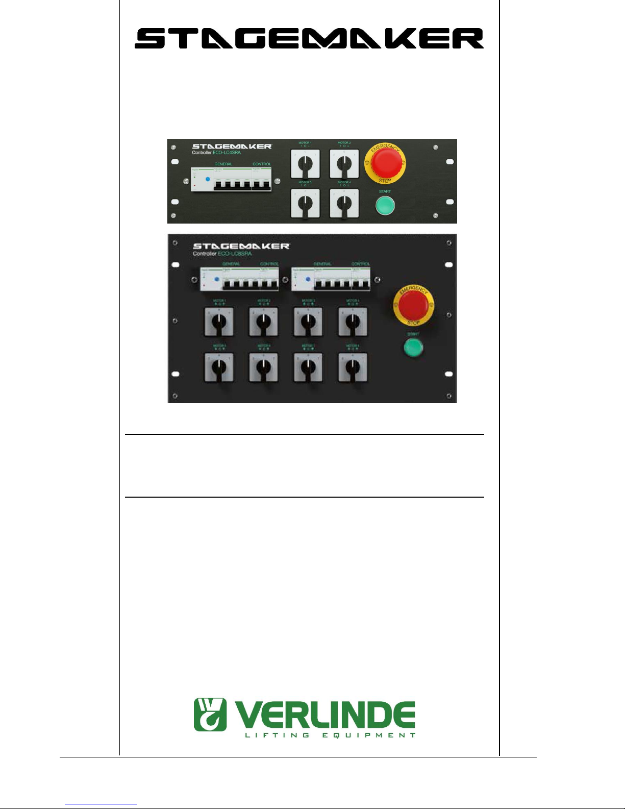
1- INTRODUCTION
STAGEMAKER® CONTROLLER was specifically developed to control VERLINDE STAGEMAKER® SR
series electric chain hoist. Controllers are available with 4 or 8 channels; they fit into a 19" rack flight case.
For more extensive applications, STAGEMAKER® CONTROLLERs can be interconnected to control systems
integrating 16 motors or even more. The standard system provides for the simultaneous activation of all the
preselected motors by means of the START button. Other interconnections are available on request.
STAGEMAKER® CONTROLLER® fully complies with the most recent European electricity standards (IEC
standards / EMC directive) and is approved by APAVE (French inspection authority). They offer great flexibility,
toughness and safety.
1.1 Characteristics / ECO controller equipment for type A hoists (Direct control):
Max. power per channel: 1.8 kW / 400V 3Phases
Power supply: 400/ 415 V 3PH+N – 50/60Hz.
Power-in plug 32 A 5p CE with phase reversing
Phase monitoring indicating lamp.
Multi 16 connector output for group of motors
And in addition plug CE form 4p 16A out for each motor
Short circuit protections : power & control circuit
Thermal protection per group of 4 motors
- Max. power per channel :1,8 kW / 400v 3 Ph
OWNER’S MANUAL
5/14
VERLINDE se réserve le droit de modifier sans préavis les caractéristiques de son matériel
VERLINDE reserves the right to alter or amend specifications of its products without notice
12/2014 VESEFRSCXSRA01A
1.2 Safety instructions -
THINGS TO DO:
•Place the controller in a protective cover (if a standard protective cover is not provided).
•Manipulate the controller with the handles located at front or on sides.
•Store the controller in its normal working position sheltered from aggressive environments (dust, humidity,
etc).
•Make sure the controller is systematically clean and free from corrosion.
•The installation of the controller must be carried out by a skilled technician.
•Make sure that connecting cables are in good condition and that the connectors are properly installed.
•Make sure connecting cables are always installed symmetrically.
•If the hoist direction does not correspond with Up / Down signals on the controller, check intermediary wiring
and change two phases.
•If none of the hoists correspond with signals, change the phases using the inversion device in the CE plug or
the reversing switch (careful to cut power beforehand).
•Only use authentic spares to replace parts.
•Always be ready to hit the emergency stop button during operations. All functions shall then be disabled.
•Before starting, make sure that the load is properly secured and installed on the hook. The safety latches must
be properly closed.
•Make sure the load is well balanced before moving it.
•Make sure that each hoist is perpendicular with the load and that it hangs freely on its chain before starting
any simultaneous action.
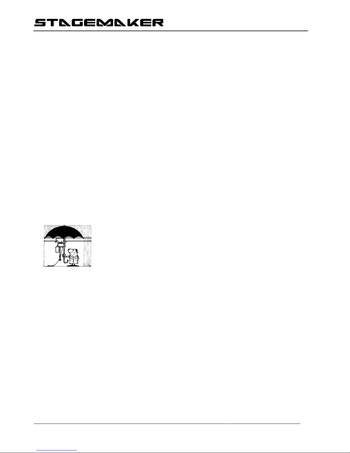
•If the system is used in the open air, use adequate guards against inclement weather.
•Operate the equipment under standard working conditions (ambient temperature, environment, etc.).
•The handling of single items or sets of beams must be entrusted to experienced operators.
•Take all necessary precautions to ensure the load is evenly distributed and avoid overloading any singe hoist
in the case of multiple use. Each hoist must be carefully checked before such use.
•Inform the supervisor of any dangerous functioning or of one which is not reassuring.
(Abnormal noise, abnormal behaviour, etc.).
Equipment used in the open air must be protected as much as possible from inclement weather.
 Loading...