

Verlinde Eurolift Owner's Manual
EUROLIFT
VERLINDE S.A. reserves the right to alter or amend the above information without notice KHVOMSXBGB2006/08
Owner’s Manual
ELECTRIC BELT HOIST HB
Annex II A
Herewith, we declare that the product :
z
Wire rope hoist
Belt hoist
Electric chain hoist
Manual chain hoist
Electric trolley
Manual winch
Complies with the following provisions applying to it:
zzzzzz - Machinery directive 98/37/EEC.
zzz z - Directive 2006/95CEE.
zzz z - "EMC" Directive 89/336/EEC
Applied harmonized standards, in particular:
zzz z - EN 60204-32, safety of the machines
zzz z - EN ISO 12100-1 / 12100-2
National regulations, standards and specifications:
zzzzzz - order of march 1st, 2004
zzz - DIN 15400; DIN 15401,
Quality system applied:
zzzzzz - EN29001/ISO9001
Technical standards and specifications complied with, in particular:
zzzzz - FEM 9.511 "classification of the mechanisms".
z - FEM 9.661 "dimensions and quality of the drive and cable lifting block
elements for mass-produced lifting devices".
zz - EN 818 "chain quality, choice criteria and technical requirements".
zzz z - FEM 9.683 "choice of motors".
z - FEM 9.755 "steps to be taken to determine the operating periods for mass-
produced motorized lifting mechanisms (S.W.P.)".
zzz - FEM 9.751 "Motorized lifting mechanism: safety"
zzz - FEM 9.901 "bases of design for the mass-produced lifting devices
for travelling cranes equipped with mass-produced lifting devices".
2009/01
Managing Director
Thomas DESCAMPS
1 - EC Declaration of conformity
VERNOUILLET
France
As defined by the EC directive relating
to machinery 98/37/EEC.

EUROLIFT
BH
OWNER’S MANUAL
Belt Hoist
Page 2
VERLINDE S.A. reserves the right to alter or amend the above information without notice KHHOMSBHGB2006/08
GENERAL WARNING
A) - It is essential to become familiar with the instruction manual:
- It is essential that you read, understand and apply this instruction manual
BEFORE starting any work.
- The user Plant Manager and the operators must strictly comply with the
following:
• This instructions manual is applicable to all operators responsible for
installing, operating, adjusting, maintaining, repairing or transporting the
machine.
• The Plant Manager is obliged to inform the operators of the requirements in
the instructions manual.
• The instructions manual must be kept for reference throughout the life of the
machine, even if it is sold or if there is a new user.
• The Plant Manager is responsible for the application of the regulations in
force.
• The instructions manual is not a training manual.
B) - General instructions:
• The machine may only be used by apt, trained and competent operators.
• The machine must only be used in accordance with the conditions specified by
the manufacturer in this instructions manual.
• Any use not conforming to the requirements in this instructions manual may
cause risks of injury to persons, damage to the property or to the environment.
• Before each use, the operator shall check that the equipment is in good
condition.
• Do not use the equipment if markings are no longer legible.
• The manufacturer declines all responsibility for the consequences of any
modifications made to the mechanical or electrical part without his written
permission. If the customer wants to make a modification, he should refer to
the manufacturer.
• Please only use our original spare parts, for safety and to benefit from the
manufacturer’s guarantee.

EUROLIFT
BH
OWNER’S MANUAL
Belt Hoist
Page 3
VERLINDE S.A. reserves the right to alter or amend the above information without notice KHHOMSBHGB2006/08
INDEX
1 CONSTRUCTION AND OPERATING PRINCIPLE .................................................4
1.1 Construction :................................................................................................. 4
1.2 Operation....................................................................................................... 4
1.3 Travelling machinery (variation speed)............................................................ 6
1.4 Travelling machinery (two speed)....................................................................8
2 RECOMMENDATIONS FOR USE .........................................................................9
3 IMPORTANT POINTS TO BE CHECKED BEFORE START UP AND AFTER
DOING ANY WORK .................................................................................................. 10
4 DOCUMENTATION AND CERTIFICATES ...........................................................11
5 START UP .........................................................................................................12
5.1 Adjusting the monorail low height loss crab ...................................................12
5.2 Connection to the network ............................................................................13
5.3 Mounting position of the travelling machinery ................................................ 14
5.4 Adjustment of top and bottom limit switches .................................................. 15
6 HANDLING AND INSTALLING THE BELT HOIST............................................... 17
6.1 Instructions installing the hoist on its support beam....................................... 17
6.2 Handling the hoist ........................................................................................17
7 INSTALLING THE HOIST ON ITS SUPPORT BEAM RAIL .................................. 18
8 PULLEY BLOCK HOOK AND BELT ................................................................... 19
9 MONITORING THE BELT ................................................................................... 21
10 LOAD LIMITER DESCRIPTION WITH DRAWING ............................................22
11 LUBRICATION ................................................................................................23
12 OPERATING INCIDENTS ................................................................................ 23
13 SPARE PARTS ...............................................................................................24

EUROLIFT
BH
OWNER’S MANUAL
Belt Hoist
Page 4
VERLINDE S.A. reserves the right to alter or amend the above information without notice KHHOMSBHGB2006/08
1 CONSTRUCTION AND OPERATING PRINCIPLE
1.1 Construction :
- Frame : Steel and SG cast iron
- Brake motor : IP 54 construction, 1 or 2 speed lifting type, built-in electromagnetic
brake
- Reduction gear : under sealed casing, greased for life, treated and ground helical
teeth
- Drum : composed of two flanges and a steel hub, designed so that the belt winds on
spirally
- Belt : the belt was specially designed for our company. it is tested and delivered with a
certificate of conformity, it has a safety factor exceeding 7, and it resistant to acids,
bases, mineral salts, solvents and oil products. It maintains their characteristics at the
following temperatures:
• Po belt : between - 20° and + 80°
• Dy belt : between - 30° and + 120°
- Electrical box : IP 55 protection, attached to hoist, and contains the following in the
standard version
• Safety transformer
• Protection by transformer fuses
• Lifting reversing switch
• Lifting temperature relay
• Top and bottom limit switch
• Load limiter relay
• Connection terminal block
- Button box : Complies with rules in force, cable length depending on the standard
lifting height.
Double push button for two lifting and translation speeds.
Emergency stop button allowing the user to isolate the hoist from the mains electricity
supply.
Optional : Additional buttons to control other movements.
- Load limiter : This electromechanical device does not change the dimensions of the
hoist. It enable a safety adjustment on site if there is overload.
- Steel construction 4-wheel crab, electric drive, 2-speed brake motor.
- Adjustable sides to allow installation of monorail on different support beam widths.
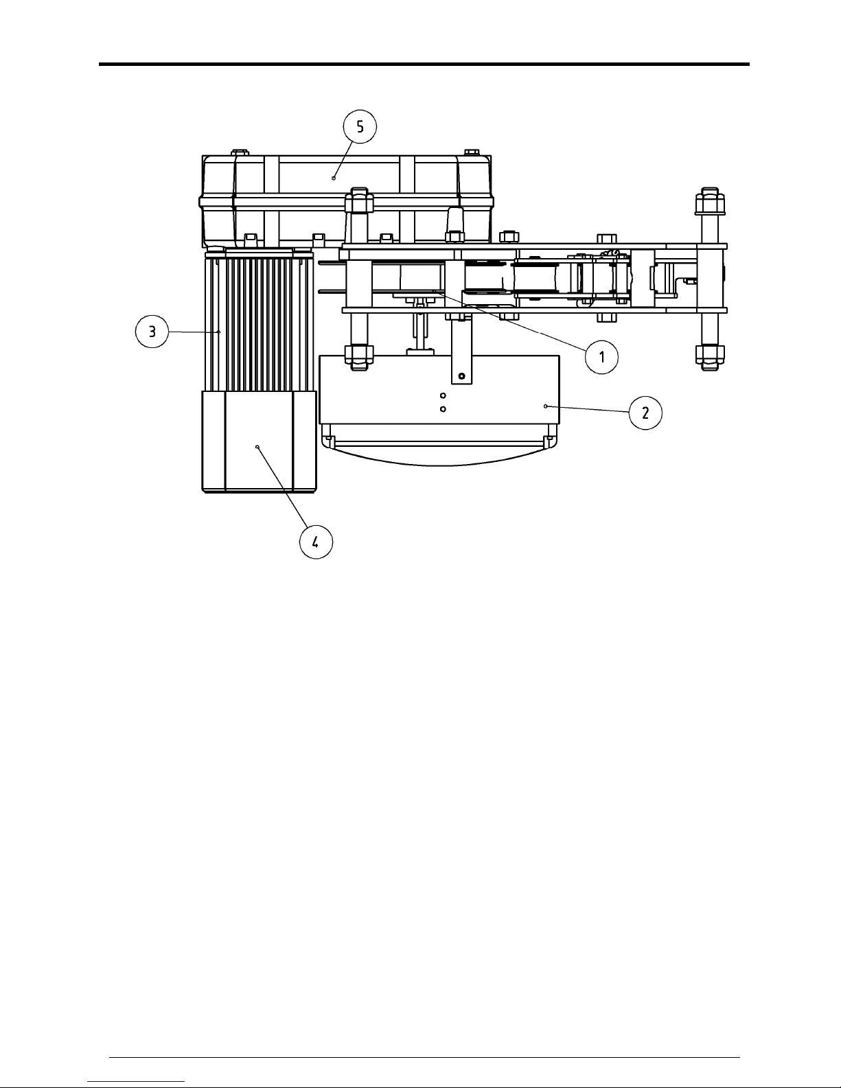
1.2 Operation
Refer to the diagram :
EUROLIFT
BH
OWNER’S MANUAL
Belt Hoist
Page 5
VERLINDE S.A. reserves the right to alter or amend the above information without notice KHHOMSBHGB2006/08
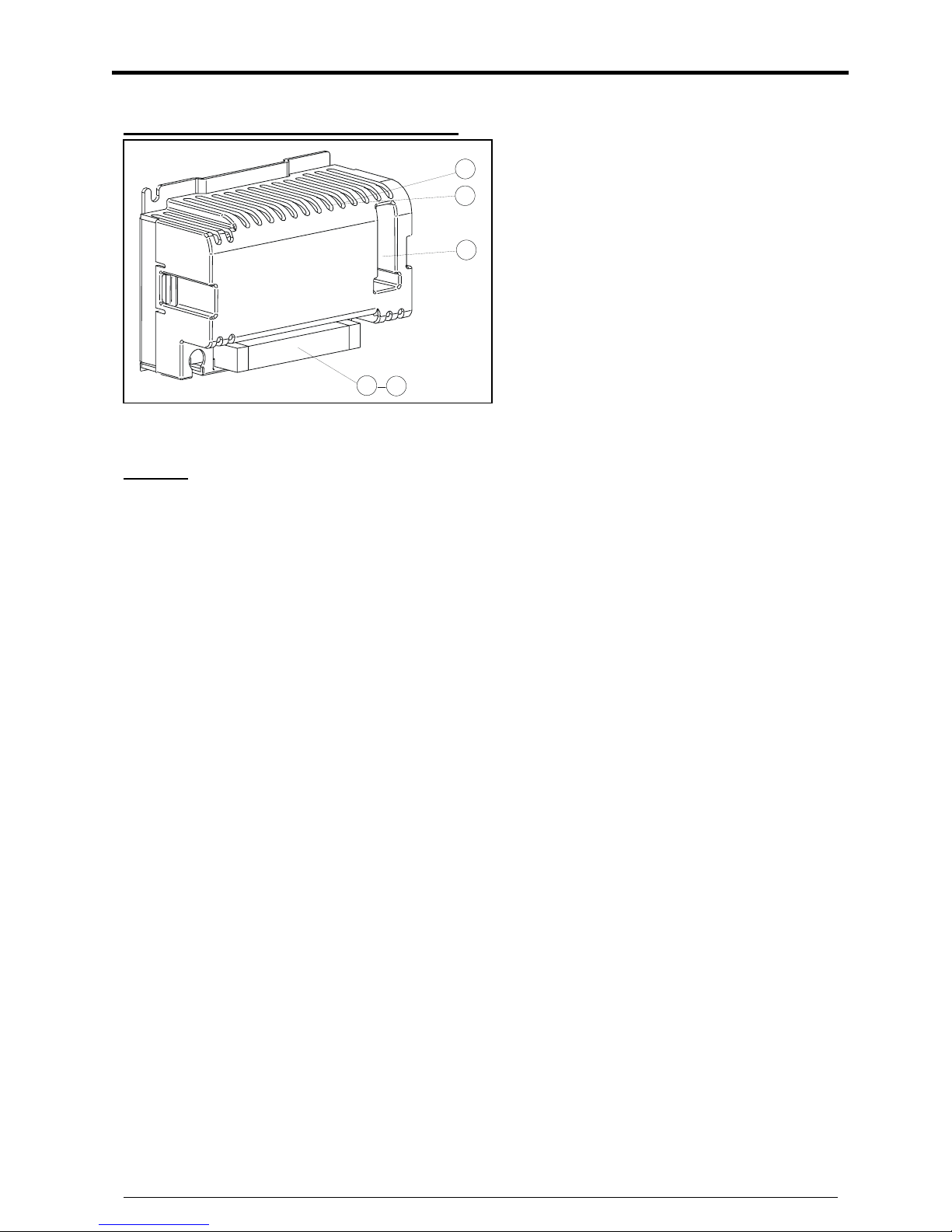
When motor 3 is powered by electricity box 2, the electromagnetic brake 4 is released,
the motor starts rotating driving lifting gear 5 and finally drum 1 rises into direct contact
with the axis of the reduction gear.
EUROLIFT
BH
OWNER’S MANUAL
Belt Hoist
Page 6
VERLINDE S.A. reserves the right to alter or amend the above information without notice KHHOMSBHGB2006/08
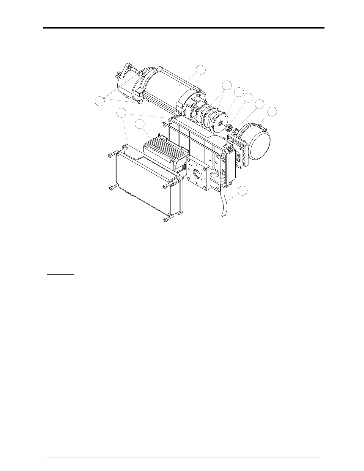
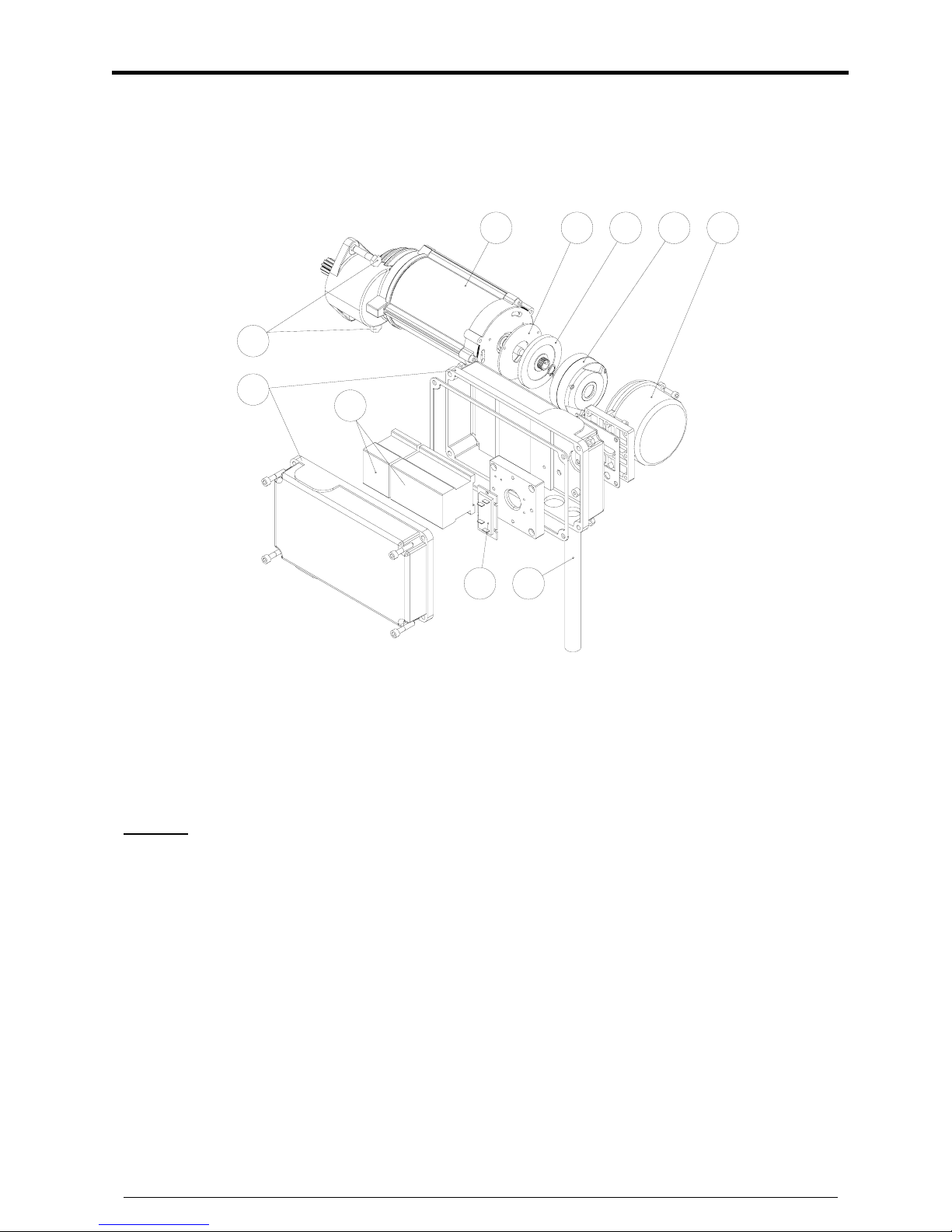
1.3 Travelling machinery (variation speed)
1
2
3
4
5
6
7
8
9
10
1 Gear/motor unit 6 Motor cover
2 Brake friction disc 7 Electric box
3 Brake disc 8 Frequency converter
4 Aluminium ring 9 Connecting cable
5 Adjustment nut 10 Fixing screws
General
The travelling machinery units are designed to perform the travelling movement of the crane
or the hoisting trolley either as a single unit or as several units. Any other kind of use (e.g.
hoisting motion) is forbidden. Machinery is suitable for indoor use. Please note possible
restrictions for special environments (e.g. galvanization plants).
EUROLIFT
BH
OWNER’S MANUAL
Belt Hoist
Page 7
VERLINDE S.A. reserves the right to alter or amend the above information without notice KHHOMSBHGB2006/08
Frequency converter for travelling motor
1 - Terminal block
2 - Red fault LED
3 - Green “OK” LED
4 - Setting DIP
General
The electrical box contains a frequency variator controlling the speed of rotation of the
travelling movement motor and brake. The frequency variator changes the rotary speed of the
travelling movement motor in accordance with the instructions given by the operator.
The frequency variator is equipped with an indicator light (3) indicating the operating
condition and another indicator (2) indicating defective operation. When the operating
indicator light (3) is lit, the frequency variator is in service. When indicator light (3) flashes, it
indicated a malfunction, though not aborting the mechanism. When fault indicator light (2)
glows, this indicates that a malfunction aborting operation has occurred.
The parameters of the frequency variator are factory-pre-set through the parameter
adjustment buttons (4). All connections to the frequency variator pass through connector (1).
3
2
4
1
X1
EUROLIFT
BH
OWNER’S MANUAL
Belt Hoist
Page 8
VERLINDE S.A. reserves the right to alter or amend the above information without notice KHHOMSBHGB2006/08
1.4 Travelling machinery (two speed)
1 2 3 4 5
6
7
8 9
10
1 Gear/motor unit 6 Electric box
2 Brake friction disc 7 Contactors
3 Brake disc 8 Rectifier
4 Brake 9 Connecting cable
5 Motor cover 10 Fixing screws
General
The travelling machinery units are designed to perform the travelling movement of the crane
or the hoisting trolley either as a single unit or as several units. Any other kind of use (e.g.
hoisting motion) is forbidden. Machinery is suitable for both indoor and outdoor use. Please
note possible restrictions for special environments (e.g. galvanization plants).
 Loading...