

Verland Ultamus Raid 4800 Setup Manual

Overland
Storage
ULTAMUS RAID 4800
Storage Appliance
Setup Guide
June 2007
10400121-101-SG

ULTAMUS RAID 4800 Setup Guide
OVERLAND STORAGE END USER LICENSE AGREEMENT (“EULA”)
IMPORTANT NOTICE - PLEASE READ THIS END USER SOFTWARE LICENSE AGREEMENT (“EULA”) CAREFULLY BEFORE USING THE
SOFTWARE CONTAINED IN THIS EQUIPMENT OR USING THIS EQUIPMENT IN ANY MANNER.
BY USING THE EQUIPMENT THAT CONTAINS THIS SOFTWARE, YOU ARE CONSENTING TO BE BOUND BY THIS AGREEMENT. IF YOU DO NOT
AGREE TO ALL OF THE TERMS OF THIS END USER AGREEMENT, PROMPTLY RETURN AND DO NOT USE THE EQUIPMENT AND THE
SOFTWARE.
1. Single User License. Subject to the terms and conditions of this EULA, Overland Storage, Inc. (“Overland”) grants to you (“Customer”) a non-exclusive,
non-transferable license to use (a) Overland software which provides the basic operating environment for Overland equipment and whether pre-installed on,
embedded in or provided with Overland equipment, and (b) the specific Overland program modules or features which have been enabled by security keys
supplied by Overland and for which Customer had paid any applicable license fees (collectively, the “Software”), both of the foregoing in object code form only:
(i) solely as pre-installed, embedded in or provided with Overland equipment owned or leased by Customer; and (ii) for key-enabled Software corresponding
to the security key(s) supplied by Overland and for the license fees paid by Customer.
2. Limitations. Except as otherwise expressly provided under this EULA, Customer will have no right, and Customer will not:
(i) make error corrections to or otherwise modify or adapt the Software nor create derivative works based upon the Software, or to permit third parties to do
the same;
(ii) copy, in whole or in part, decompile, translate, reverse engineer, disassemble or otherwise reduce the Software to human-readable form; or
(iii) remove the Software from the equipment in which it is embedded.
3. Upgrades and Additional Copies. For purposes of this EULA, “Software” will also include (and the terms and conditions of this EULA will apply to) any
upgrades, updates, bug fixes or modified versions (collectively, “Upgrades”) or backup copies of the Software licensed or provided to Customer by Overland or
an authorized distributor for which Customer had paid the applicable license fees and holds the corresponding software keys. Notwithstanding the foregoing,
Overland will have no obligation to provide any Upgrades under this EULA. If Upgrades are provided, (i) Customer has no license or right to use any such
additional copies or Upgrades unless Customer, at the time of acquiring such copy or Upgrade, already holds a valid license and the corresponding security
keys to the original Software; and (ii) use of the Upgrades is limited to Overland equipment for which Customer is the original End-User purchase or lessee.
4. U.S. Government Restriction Rights. The Software was developed at private expense and is provided with “RESTRICTED RIGHTS” as set forth in this
License Agreement. Use, duplication or disclosure by the United States government is subject to restrictions as set forth in FAR 52.227-14 and DFARS
252.227-7013 et seq., or its successors. The use of this Software constitutes acknowledgement of Company’s and its licensors’ rights in the Software.
5. Notices of Proprietary Rights. Customer will maintain and reproduce all trademark, copyright, patent, and notices of other proprietary rights on all
copies, in any form, of the Software in the same form and manner that such trademark, copyright, patent, and notices of other rights are included on the
Software. Except as expressly authorized in this EULA, Customer will not make any copies or duplicates of any Software without the prior written permission
of Overland.
6. Proprietary Rights. The Softw are is and will r ema in the sole and exclusive property of Overland. Software is licensed, not sold, by Overland hereunder.
Any references to terms in connection with the foregoing, such as “sale”, “purchase” or “sell” will be interpreted as licensed
basis hereunder and as otherwise provided in this EULA. Overland’s rights under this Section will include, but not be limited to: (i) all copies of the Software,
in whole and in part; and (ii) all intellectual property rights in the Software.
7. Confidential Information. Customer will not disclose or, except as expressly permitted in this EULA, use any Software or other technical information
disclosed to Customer by Overland (“Confiden tia l In form ati on”) . Cu stom er w ill take all reasonable measures to maintain the confidentiality of all Confidential
Information in Customer’s possession or control, which will in no event be less than the measures Customer uses to maintain the confidentiality of Customer’s
own information of equal importance. Confidential Information will not include information that: (i) is in or enters the public domain without breach of this
EULA; (ii) Customer receives from a third party without restriction on disclosure and without breach of a nondisclosure obligation; or (iii) Customer develops
independently, which Customer can prove with written evidence.
The Confidential Information is a trade secret of Overland, the disclosure of which would cause substantial harm to Overland that could not be remedied by
the payment of damages alone. Accordingly, Overland will be entitled to preliminary and permanent injunctive relief and other equitable relief for any breach
of this Section.
8. Limited Software Warranty. Overland warrants that the Software will substantially conform to its published specifications for a period of 90 days from
the later of receipt of the equipment containing the Software or receipt of access to the Software. This limited warranty extends only to Customer as the
original licensee. Provided that (a) Customer has notified Overland of such substantial non-conformance during the applicable warranty period, and (b)
Overland has confirmed such Software to be substantially non-conforming, as Customer’s sole and exclusive remedy and Overland’s and its suppliers’ entire
liability under this limited warranty, Overland will, at its option, repair, replace, or refund the Software pursuant to Overland’s then-current warranty policy.
Except as expressly provided in this EULA, the Software is provided “AS IS” without warranty of any kind. Overland does not warrant that the Software is
error free or that Customer will be able to operate the Software without problems or interruptions. Overland reserves the right to charge additional fees for
repairs or replacements performed outside of the 90-day limited warranty period.
This warranty does not apply if the Software or the Overland equipment in which the Software is embedded (i) is licensed for beta, evaluation, testing or
demonstration purposes for which Overland does not receive a license fee, (ii) has been altered, except by Overland, (iii) has not been installed, operated,
repaired, or maintained in accordance with instructions supplied by Overland, (iv) has been subjected to abnormal physical or electrical stress or to misuse,
negligence, or accident, or (v) is used in ultra-hazardous activities.
9. Disclaimer. EXCEPT AS SPECIFIED IN THIS EULA, ALL EXPRESS OR IMPLIED CONDITIONS, REPRESENTATIONS, AND WARRANTIES
INCLUDING, WITHOUT LIMITATION, ANY IMPLIED WARRANTY OR CONDITION OF MERCHANTABILITY, FITNESS FOR A PARTICULAR
PURPOSE, NON-INFRINGEMENT, SATISFACTORY QUALITY OR ARISING FROM A COURSE OF DEALING, USAGE, OR TRADE PRACTICE, ARE
HEREBY EXCLUDED TO THE EXTENT ALLOWED BY APPLICABLE LAW. IN NO EVENT WILL OVERLAND OR ITS SUPPLIERS BE LIABLE FOR
ANY LOST REVENUE, PROFIT, OR DATA, OR FOR SPECIAL, INDIRECT, CONSEQUENTIAL, INCIDENTAL, OR PUNITIVE DAMAGES HOWEVER
CAUSED AND REGARDLESS OF THE THEORY OF LIABILITY ARISING OUT OF THE USE OF OR INABILITY TO USE THE SOFTWARE EVEN IF
OVERLAND OR ITS SUPPLIERS HAVE BEEN ADVISED OF THE POSSIBILITY OF SUCH DAMAGES. IN NO EVENT WILL OVERLAND’S TOTAL
LIABILITY TO CUSTOMER, WHETHER IN CONTRACT, TORT (INCLUDING NEGLIGENCE), OR OTHERWISE, EXCEED THE PRICE PAID BY
CUSTOMER. THE FOREGOING LIMITATIONS WILL APPLY EVEN IF THE ABOVE-STATED WARRANTY FAILS OF ITS ESSENTIAL PURPOSE.
Each party recognizes and agrees that the warranty disclaimers and liability and remedy limitations in this EULA are material bargained for bases of this
EULA and that they have been taken into account and reflected in determining the consideration to be given by each party under this EULA and in the
decision by each party to enter into this EULA.
10. Term and Termination. This EULA is effective until terminated. Customer’s license rights under this EULA will terminate immediately without notice
from Overland if Customer fails to comply with any provision of this EULA. Upon termination, Customer must destroy all copies of Software and the
corresponding security keys in its possession or control.
11. Compliance With Law. Each party will comply with all applicable laws, rules and regulations in connection with its activities under this EULA. Without
limiting the foregoing, the Software, including technical data, is subject to United States export control laws, including the United States Export
Administration Act and its associated regulations, and may be subject to export or import regulations in other countries. Customer will comply strictly with
all such regulations and acknowledges that Customer has the responsibility to obtain licenses to export, re-export, or import the Software.
rights granted on a non-exclusive
ii X 10400121-101-SG 06/07

ULTAMUS RAID 4800 Setup Guide
12. Restricted Rights. The Software will be classified as “commercial computer software” as defined in the applicable provisions of the Federal Acquisition
Regulation (the “FAR”) and supplements thereto, including the Department of Defense (DoD) FAR Supplement (the “DFARS”). The parties acknowledge that
the Software was developed entirely at private expense and that no part of the Software was first produced in the performance of a Government contract. If
the Software is supplied for use by DoD, the Software is delivered subject to the terms of this EULA and either (i) in accordance with DFARS 227.702-1(a)
and 227.7202-3(a), or (ii) with restricted rights in accordance with DFARS 252.227-7013(c)(1)(ii) (OCT 1988), as applicable. If the Software is supplied for use
by a Federal agency other than DoD, the Software is restricted computer software delivered subject to the terms of this EULA and (i) FAR 12.212(a); (ii) FAR
52.227-19; or (iii) FAR 52.227-14 (ALT III), as applicable.
13. Third Party Software. Third party suppliers of materials integrated with the Overland equipment disclaim all implied warranties, including the implied
warranties of merchantability and fitness for a particular purpose. The collective liabilities of the seller/licensor and its third party suppliers are subject to
the limitation of liabilities described in this agreement. The third party supplier is an intended beneficiary of this limitation.” Third party suppliers disclaim
all liability for consequential or other indirect damages or for loss of or damage to data or records.
14. General. This EULA will bind and inure to the benefit of each party’s successors and assigns, provided that Customer may not assign or transfer this
EULA, in whole or in part, without Overland’s written consent.
This EULA will be governed by and construed in accordance with the laws of the State of California, United States of America, as if performed wholly within
the state and without giving effect to the principles of conflict of law.
No failure of either party to exercise or enforce any of its rights under this EULA will act as a waiver of such rights.
Any waivers or amendments will be effective only if made in writing by non-preprinted agreements clearly understood by both parties to be an amendment
or waiver and signed by a representative of the respective parties authorized to bind the parties.
If any portion hereof is found to be void or unenforceable, the remaining provisions of this EULA will remain in full force and effect.
This EULA is the complete and exclusive agreement between the parties with respect to the subject matter hereof, superseding and replacing any and all
prior agreements, communications, and understandings (both written and oral) regarding such subject matter.
Any notice, report, approval or consent required or permitted hereunder will be in writing and will be deemed to have been duly given if delivered personally
or mailed by first-class, registered or certified US mail, postage prepaid to the respective addresses of the parties. The prevailing party in any action to enforce
this EULA will be entitled to recover costs and expenses including, without limitation, reasonable attorneys’ fees.
A material breach of this EULA adversely affecting Overland’s proprietary rights in the Software would cause irreparable injury to Overland for which
monetary damages would not be an adequate remedy and that Overland will be entitled to equitable relief in addition to any remedies it may have hereunder
or at law.
©2007 Overland Storage, Inc. All rights reserved.
Overland®, Overland Storage®, XchangeNOW®, VR2®, WebTLC®, PowerLoader®, LoaderXpress®, NEO SERIES®, and REO SERIES® are registered
trademarks of Overland Storage, Inc. Simply iSCSI™, Simply Protected™, Simply Protected Storage™, SnapWrite™, ULTAMUS™, ULTAMUS SERIES™,
ULTAMUS PRO™, ULTAMUS RAID™, REO™, NEO™, ARCvault™, ARCvault SERIES™, Protection OS™, Multi-SitePAC™, NDMP PAC™,
CompliancePAC™, VTLPac™, and D2D2T™ are trademarks of Overland Storage, Inc.
All other brand names or trademarks are the property of their respective owners.
The names of companies and individuals used in examples are fictitious and intended to illustrate the use of the software. Any resemblance to actual
companies or individuals, whether past or present, is coincidental.
PROPRIETARY NOTICE
All information contained in or disclosed by this document is considered proprietary by Overland Storage. By accepting this material the recipient agrees that
this material and the information contained therein are held in confidence and in trust and will not be used, reproduced in whole or in part, nor its contents
revealed to others, except to meet the purpose for which it was delivered. It is understood that no right is conveyed to reproduce or have reproduced any item
herein disclosed without express permission from Overland Storage.
Overland Storage provides this manual as is, without warranty of any kind, either expressed or implied, including, but not limited to, the implied warranties
of merchantability and fitness for a particular purpose. Overland Storage may make improvements or changes in the product(s) or programs described in this
manual at any time. These changes will be incorporated in new editions of this publication.
Overland Storage assumes no responsibility for the accuracy, completeness, sufficiency, or usefulness of this manual, nor for any problem that might arise
from the use of the information in this manual.
10400121-101-SG 06/07 W iii

ULTAMUS RAID 4800 Setup Guide
Overland Storage, Inc.
4820 Overland Avenue
San Diego, CA 92123
U.S.A.
Tel: 1 (800) 729-8725 (toll-free U.S.)
Tel: +1 (858) 571-5555 Option 5 (International)
Fax: +1 (858) 571-0982 (general)
Fax: +1 (858) 571-3664 (sales)
www.overlandstorage.com
X 10400121-101-SG 06/07
iv

Setup Guide
Chapter 1 Introduction . . . . . . . . . . . . . . . . . . . . . . . . . . . . . . . . . . . . 1
Contents
General . . . . . . . . . . . . . . . . . . . . . . . . . . . . . . . . . . . . 1
ULTAMUS RAID 4800 Array . . . . . . . . . . . . . . . . . . . . . . . . . . . . . 2
ULTAMUS RAID 4800x Expansion Array . . . . . . . . . . . . . . . . . . . . . . . . 2
Enclosure Chassis. . . . . . . . . . . . . . . . . . . . . . . . . . . . . . . . . 4
EIP Card . . . . . . . . . . . . . . . . . . . . . . . . . . . . . . . . . . . 6
SAS-SATA Channel Card . . . . . . . . . . . . . . . . . . . . . . . . . . . . 6
SAS-SATA Channel Card . . . . . . . . . . . . . . . . . . . . . . . . . . . . 7
Indicators and Switches . . . . . . . . . . . . . . . . . . . . . . . . . . . . . . 7
Display Panel . . . . . . . . . . . . . . . . . . . . . . . . . . . . . . . . . 7
Enclosure Switches . . . . . . . . . . . . . . . . . . . . . . . . . . . . . . . 9
Plug-in Modules . . . . . . . . . . . . . . . . . . . . . . . . . . . . . . . . 10
Power Supply/Cooling Module . . . . . . . . . . . . . . . . . . . . . . . . . 10
ACRS Module (Optional) . . . . . . . . . . . . . . . . . . . . . . . . . . . 11
RAID Controller Module . . . . . . . . . . . . . . . . . . . . . . . . . . . . 12
Backup Battery . . . . . . . . . . . . . . . . . . . . . . . . . . . . . . . 15
ULTAMUS RAID Manager Storage Management Software . . . . . . . . . . . . . 16
EBOD I/O Module . . . . . . . . . . . . . . . . . . . . . . . . . . . . . . 16
Drive Carrier Module . . . . . . . . . . . . . . . . . . . . . . . . . . . . . 17
Visible and Audible Alarms . . . . . . . . . . . . . . . . . . . . . . . . . . . 18
Chapter 2 Installing and Connecting . . . . . . . . . . . . . . . . . . . . . . . . . . . . . . 19
Preparation of Site and Host Server . . . . . . . . . . . . . . . . . . . . . . . . 19
Unpacking the ULTAMUS RAID storage array Array . . . . . . . . . . . . . . . . . 19
Introduction . . . . . . . . . . . . . . . . . . . . . . . . . . . . . . . . . . 20
Planning Your Installation . . . . . . . . . . . . . . . . . . . . . . . . . . . . 20
Drive Bay Numbering Convention . . . . . . . . . . . . . . . . . . . . . . . 21
Enclosure Installation Pre-Requisites . . . . . . . . . . . . . . . . . . . . . . . . 21
Preparation of Site and Host Server . . . . . . . . . . . . . . . . . . . . . . . 22
Unpacking the Enclosure System . . . . . . . . . . . . . . . . . . . . . . . . 22
Planning and Configuring Your Installation . . . . . . . . . . . . . . . . . . . . 23
Rack Installation Pre-Requisites . . . . . . . . . . . . . . . . . . . . . . . . . 23
Rack Installation Procedure . . . . . . . . . . . . . . . . . . . . . . . . . . . 23
Parts Check List . . . . . . . . . . . . . . . . . . . . . . . . . . . . . . . 24
Tools Required . . . . . . . . . . . . . . . . . . . . . . . . . . . . . . . . 24
Assemble the Mounting Rails in the Rack . . . . . . . . . . . . . . . . . . . . 24
Assemble the Enclosure Rails to the Enclosure . . . . . . . . . . . . . . . . . . 26
Install the Enclosure into the Rack . . . . . . . . . . . . . . . . . . . . . . . 26
Grounding Checks . . . . . . . . . . . . . . . . . . . . . . . . . . . . . . 29
Power and Data Cable Installation . . . . . . . . . . . . . . . . . . . . . . . 29
10400121-101-SG 06/07 W v

ULTAMUS RAID 4800 Setup Guide Contents
Cabling the Enclosures . . . . . . . . . . . . . . . . . . . . . . . . . . . . . 32
Cabling Multiple Enclosures . . . . . . . . . . . . . . . . . . . . . . . . . . . 34
Ethernet Connection . . . . . . . . . . . . . . . . . . . . . . . . . . . . . . 35
Drive Carrier Module Installation . . . . . . . . . . . . . . . . . . . . . . . . . 35
Supported Configurations . . . . . . . . . . . . . . . . . . . . . . . . . . . . 39
Enclosure Switch Settings . . . . . . . . . . . . . . . . . . . . . . . . . . . 39
Management Interfaces . . . . . . . . . . . . . . . . . . . . . . . . . . . . 39
ULTAMUS RAID Manager Software . . . . . . . . . . . . . . . . . . . . . . . 39
Chapter 3 Powerup and Startup . . . . . . . . . . . . . . . . . . . . . . . . . . . . . . . . . 41
Before You Begin. . . . . . . . . . . . . . . . . . . . . . . . . . . . . . . . 41
System Power Up . . . . . . . . . . . . . . . . . . . . . . . . . . . . . . . 41
Power Supply/Cooling Module LEDs . . . . . . . . . . . . . . . . . . . . . . 41
Display Panel Status Indicators . . . . . . . . . . . . . . . . . . . . . . . . . . 42
Display Panel LEDs . . . . . . . . . . . . . . . . . . . . . . . . . . . . . . 43
Display Panel Indicators . . . . . . . . . . . . . . . . . . . . . . . . . . . . 43
Starting the Drives . . . . . . . . . . . . . . . . . . . . . . . . . . . . . . . 44
Disk Drive Fault LEDs . . . . . . . . . . . . . . . . . . . . . . . . . . . . . 44
Disk Drive Activity LEDs . . . . . . . . . . . . . . . . . . . . . . . . . . . . 44
Chapter 4 ULTAMUS RAID Manager Software . . . . . . . . . . . . . . . . . . . . . . . . . . . 45
Volume Size Reporting . . . . . . . . . . . . . . . . . . . . . . . . . . . . . 45
Troubleshooting Assistance . . . . . . . . . . . . . . . . . . . . . . . . . . . 46
Embedded ULTAMUS RAID Manager Initial Setup . . . . . . . . . . . . . . . . . . 46
Setting up the Embedded ULTAMUS RAID Manager . . . . . . . . . . . . . . . . 47
Using the ULTAMUS RAID Manager . . . . . . . . . . . . . . . . . . . . . . . . 48
Appendix A Faults and Troubleshooting . . . . . . . . . . . . . . . . . . . . . . . . . . . . 49
Overview . . . . . . . . . . . . . . . . . . . . . . . . . . . . . . . . . . . 49
Initial Start-up Problems . . . . . . . . . . . . . . . . . . . . . . . . . . . . . 49
Faulty Cords. . . . . . . . . . . . . . . . . . . . . . . . . . . . . . . . . 49
Alarm Sounds On Power Up . . . . . . . . . . . . . . . . . . . . . . . . . . 49
Green Controller OK LED on RAID Controller Not Lit . . . . . . . . . . . . . . . . 49
Computer Doesn’t Recognize the ULTAMUS RAID storage array . . . . . . . . . . . 49
Status Indicators (LEDs) . . . . . . . . . . . . . . . . . . . . . . . . . . . . . 50
Power Supply/Cooling Module LEDs . . . . . . . . . . . . . . . . . . . . . . 50
Channel Card LEDs. . . . . . . . . . . . . . . . . . . . . . . . . . . . . . 50
RAID Controller Module . . . . . . . . . . . . . . . . . . . . . . . . . . . . 51
EBOD I/O Module LEDs . . . . . . . . . . . . . . . . . . . . . . . . . . . . 52
EIP Card LEDs . . . . . . . . . . . . . . . . . . . . . . . . . . . . . . . . 53
Display Panel LEDs . . . . . . . . . . . . . . . . . . . . . . . . . . . . . . 53
Enclosure Display Panel LCD . . . . . . . . . . . . . . . . . . . . . . . . . . 55
Audible Alarm . . . . . . . . . . . . . . . . . . . . . . . . . . . . . . . . . 57
Audible Alarm Mute . . . . . . . . . . . . . . . . . . . . . . . . . . . . . 57
Troubleshooting . . . . . . . . . . . . . . . . . . . . . . . . . . . . . . . . 58
Power Supply/Cooling Module Faults . . . . . . . . . . . . . . . . . . . . . . 58
Thermal Control . . . . . . . . . . . . . . . . . . . . . . . . . . . . . . . 58
Thermal Alarm . . . . . . . . . . . . . . . . . . . . . . . . . . . . . . . . 59
Thermal Shutdown . . . . . . . . . . . . . . . . . . . . . . . . . . . . . . 59
Appendix B Specifications . . . . . . . . . . . . . . . . . . . . . . . . . . . . . . . . . 61
Dimensions . . . . . . . . . . . . . . . . . . . . . . . . . . . . . . . . . 61
Weight . . . . . . . . . . . . . . . . . . . . . . . . . . . . . . . . . . . 61
Power Source . . . . . . . . . . . . . . . . . . . . . . . . . . . . . . . . 61
vi X 10400121-101-SG 06/07

ULTAMUS RAID 4800 Setup Guide Contents
AC Power (450W Power Supply/Cooling Module) . . . . . . . . . . . . . . . . . 62
Power Supply Safety and EMC Compliance . . . . . . . . . . . . . . . . . . . 62
Power Cord . . . . . . . . . . . . . . . . . . . . . . . . . . . . . . . . . 62
ACRS Module . . . . . . . . . . . . . . . . . . . . . . . . . . . . . . . . 63
Environment. . . . . . . . . . . . . . . . . . . . . . . . . . . . . . . . . 63
Interfaces - RAID Controller . . . . . . . . . . . . . . . . . . . . . . . . . . 64
Interfaces - EBOD I/O Module . . . . . . . . . . . . . . . . . . . . . . . . . 64
RAID Controller Module Specification . . . . . . . . . . . . . . . . . . . . . . 64
EBOD I/O Module Specification . . . . . . . . . . . . . . . . . . . . . . . . 64
Drive Carrier Module Specification . . . . . . . . . . . . . . . . . . . . . . . 65
Software Enclosure Services (SES) Support . . . . . . . . . . . . . . . . . . . . 65
10400121-101-SG 06/07 W vii

ULTAMUS RAID 4800 Setup Guide Contents
viii X 10400121-101-SG 06/07
1
CHAPTER
General
Introduction
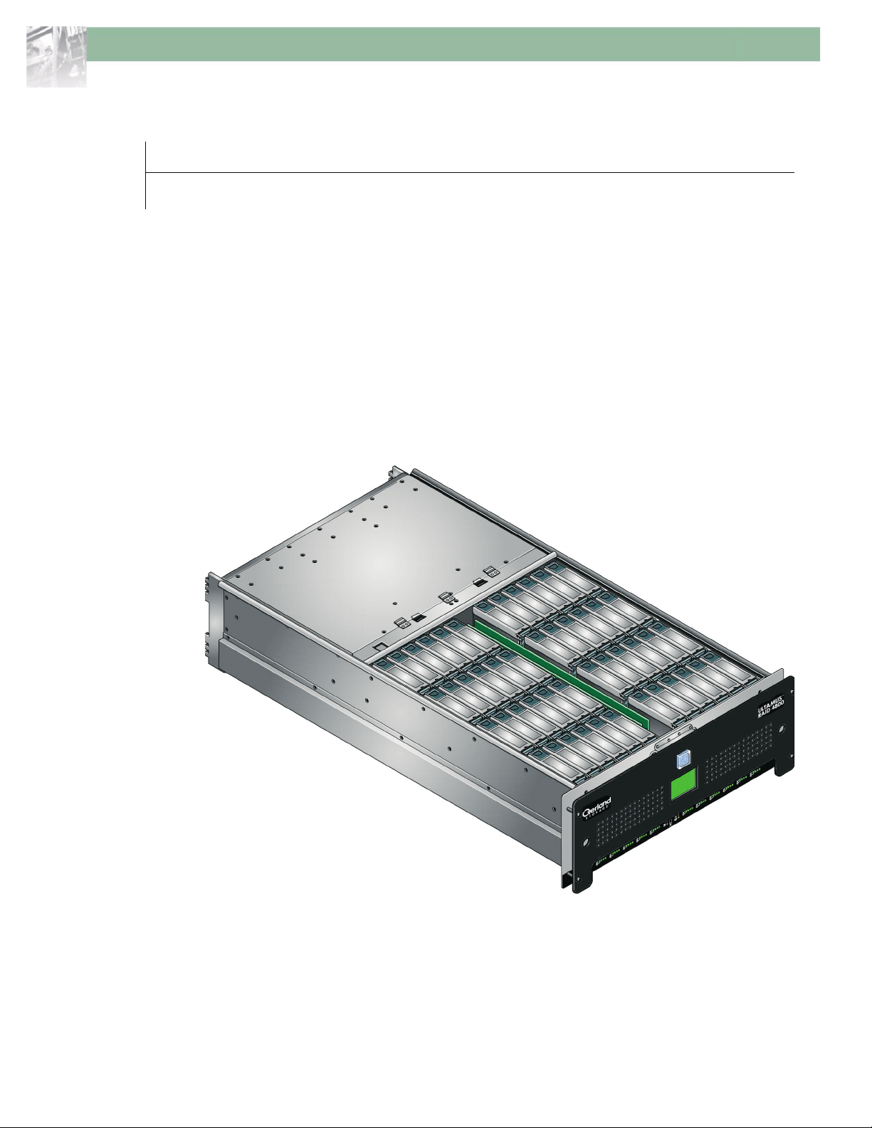
The ULTAMUS RAID 4800 platform is a 4U SATA disk drive RAID enclosure, with either
24 or 48 drives, capable of providing up to 36TB of data storage per enclosure using 750GB
capacity disk drives.
Figure 1-1: ULTAMUS RAID 4800 Storage System
Expansion of the system is achieved by connecting an ULTAMUS RAID 4800x Expansion
Array to the main array thus increasing the number of drives up to a possible 96 drives and
72TB of storage using 750GB drives. The two arrays are connected together using a SAS
cable.
10400121-101-SG 06/07 W 1
ULTAMUS RAID 4800 Setup Guide Chapter 1
ULTAMUS RAID 4800 Array
The ULTAMUS RAID 4800 as supplied contains:
• Chassis and Backplane with integral (front panel mounted) Operator’s Panel
• Up to 48 Drive Carrier Modules, using SATA disk drives
• Three plug-in 100-240V AC, 350W Power Supply Modules with cooling fans
• Two plug-in RAID Controller Modules, incorporating the ULTAMUS RAID Manager
software
Figure 1-2: ULTAMUS RAID 4800 Rear View
ULTAMUS RAID 4800x Expansion Array
The ULTAMUS RAID 4800x Expansion Array as supplied contains:
• Chassis and Backplane with integral (front panel mounted) Operator’s Panel
• Up to 48 Drive Carrier Modules, using SATA disk drives
• Three plug-in 100-240V AC, 350W Power Supply Modules with cooling fans
• Two plug-in EBOD I/O Modules
2 X 10400121-101-SG 06/07
ULTAMUS RAID 4800 Setup Guide Chapter 1
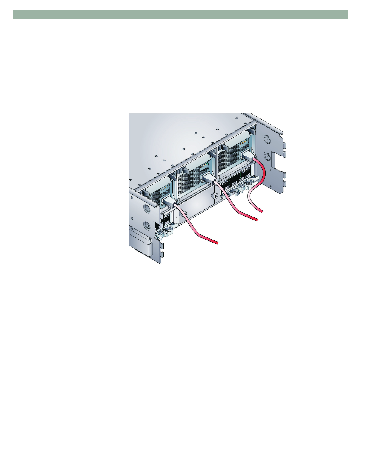
Figure 1-3: ULTAMUS RAID 4800x Rear View (with ACRS Installed)
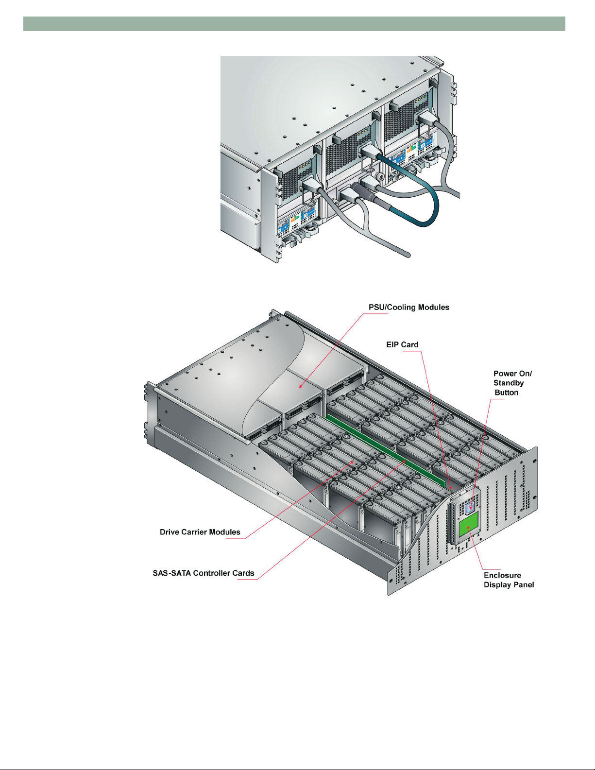
Figure 1-4: ULTAMUS RAID 4800 Enclosure Components (Cutaway)
10400121-101-SG 06/07 W 3
ULTAMUS RAID 4800 Setup Guide Chapter 1
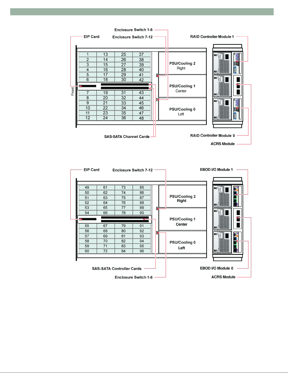
Figure 1-5: ULTAMUS RAID 4800 Module Locations
Figure 1-6: ULTAMUS RAID 4800x Module Locations
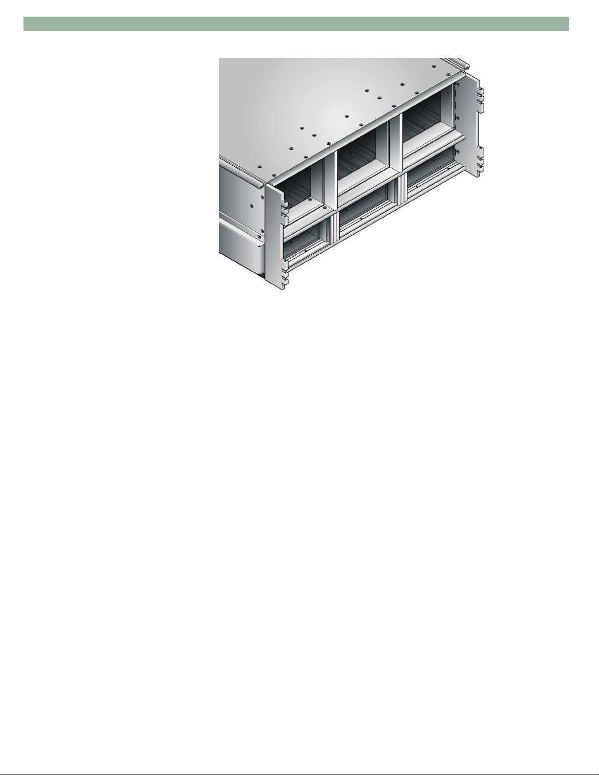
Enclosure Chassis
The chassis consists of a sheet metal enclosure assembly containing an integrated
Baseplane and Backplane PCB, a drive module runner system, and a Display Panel with
status LEDs located on the front.
4 X 10400121-101-SG 06/07
ULTAMUS RAID 4800 Setup Guide Chapter 1
Figure 1-7: Rear View of Enclosure Chassis
The chassis is fitted with 19 inch rack mounting rails which enable it to be installed into a
19 inch rack cabinet with a 1000mm (40 inches) depth and uses 4 EIA units of rack space
(i.e. 7" high).
• The Backplane PCB provides logic level signal and low voltage power distribution paths.
• The Baseplane includes connectors to drive bays, backplane and SAS-SATA channel
cards, internal monitoring LEDs and ambient temperature sensor.
This chassis assembly contains 48 drive bays, arranged in two groups each comprising 4
banks of 6 bays, located in the front section of the chassis (see Figure 1-5). Each drive bay
accommodates a plug-in drive carrier module which houses low profile, 1 inch high, 3.5 inch
form factor drives. Drives are loaded via the top of the enclosure.
Note: A drive bay is defined as the space required to house a single, 1.0 inch high, 3.5 inch
disk drive in its carrier module.
Located between the two groups of drive bays are the Enclosure Interface Processor (EIP)
card and the SAS-SATA Channel cards, which are pre-installed.
An integral Enclosure Display Panel assembly is mounted at the front of the chassis
assembly which includes:
• An Audible Alarm and an Alarm Mute switch.
• An LED status display.
• An LCD which indicates Power Supply/Cooling Module, Fan, or System failure.
• A Power On/Standby button.
At the rear, the chassis assembly contains six module bays to house the three Power
Supply/Cooling modules, two FC-SAS RAID Controller modules (ULTAMUS RAID 4800)
or SAS EBOD I/O modules (ULTAMUS RAID 4800x), and one optional ACRS (AC
Redundant Switch) module.
10400121-101-SG 06/07 W 5
ULTAMUS RAID 4800 Setup Guide Chapter 1
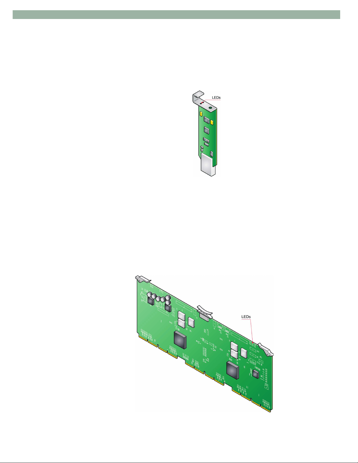
EIP Card
The Enclosure Interface Processor (EIP) card contains a processor which interfaces to
devices on the baseplane, and RAID Controllers or EBOD I/O modules to monitor internal
functions and mode settings. Monitoring information from the EIP card is displayed on the
LEDs and the LCD located on the Display Panel. Mode settings are selected via the
Enclosure switches, mounted on the backplane which is located between the drive area and
rear module bays.
The EIP card incorporates the following LED indicators:
• Fault LED.
• Address Mode Error LED (not used).
The EIP card is a serviceable PCB which may be replaced by trained personnel.
SAS-SATA Channel Card
The SAS-SATA Channel cards each contain SAS expander devices that provide switchbased connectivity to SATA drives in the enclosure. In dual port applications, a SATA port
selector located on a dongle on the drive carrier is used to enable dual port capability.
Figure 1-8: EIP Card
Figure 1-9: SAS-SATA Channel Card
6 X 10400121-101-SG 06/07

ULTAMUS RAID 4800 Setup Guide Chapter 1
SAS-SATA Channel Card
The SAS-SATA Channel cards each contain SAS expander devices that provide switchbased connectivity to SATA drives in the enclosure. In dual port applications, a SATA port
selector located on a dongle on the drive carrier is used to enable dual port capability.
The SAS-SATA Channel cards allow up to 6 high speed differential SAS connections to
each of the EBOD I/O modules or RAID Controller modules (12 in total to each module) and
communicate with all 48 drives in the enclosure.
The card incorporates an amber Fault LED and two green Status LEDs, and is a
serviceable PCB which may be replaced by trained personnel.
Table 1–1: SAS-SATA Channel Card LEDs
LED State Status
Green Flashes slowly, 0.5Hz. Normal operations.
Green Flashes fast, 2Hz. Initialization error.
Amber On steady. Card in reset or hot swap error.
Indicators and Switches
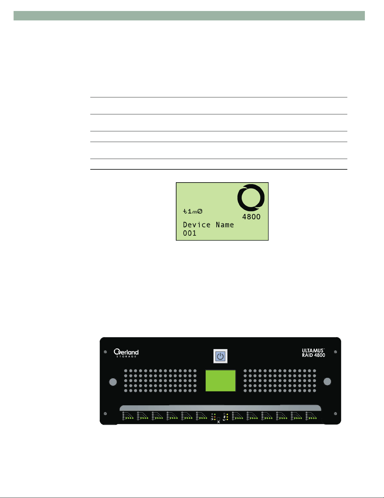
Display Panel
Supplied as an integral part of the enclosure chassis, the Display Panel and its location on
the front panel is shown in Figure 1-10.
Figure 1-10: Front Display Panel Indicators and Buttons
Display Panel Indicators and Buttons
The Display Panel assembly includes:
• Light Emitting Diodes (LEDs) which show the status for all plug-in modules
Table 1–2).
(see
• An LCD (Liquid Crystal Display), indicating Power Supply/Cooling module, and/or
System failures (
• An Audible Alarm which indicates when a fault state is present with a Alarm Mute
push-button.
• A Power On/Standby button.
Figure 1-11).
10400121-101-SG 06/07 W 7
ULTAMUS RAID 4800 Setup Guide Chapter 1
Table 1–2: LED Definitions
LED Definition Normal Status Fault Status
Power On Enclosure Power status ON GREEN - Power ON
ON YELLOW - System is
running from Standby
Voltage and not Powered
ON
-
PSU/Cooling Module
Status (amber)
Rear I/O Module
Status (amber)
Drive Fault (yellow) Not Applicable - -
Channel Card Fault
(yellow)
EIP Card Fault (yellow) EIP card fault OFF ON
Power Supply/Cooling Module fault
or enclosure over-temperature
RAID Controller or EBOD I/O
Module detected fault
Internal SAS-SATA Channel card
fault
Figure 1-11: Front Panel LCD Screen
OFF ON
OFF ON
OFF ON
For further information on the LCD states, Appendix A, Faults and Troubleshooting.
Front Panel - Drive Activity LEDs
The front panel assembly includes 48 Drive Activity LEDs, located along the bottom of the
panel and arranged in twelve groups of four LEDs for the column of drives, shown below
and on the following page.
Drive Activity LEDs are illuminated when drives are installed and will flash during drive
I/O activity.
Figure 1-12: Front Panel Showing Drive LEDs
8 X 10400121-101-SG 06/07
ULTAMUS RAID 4800 Setup Guide Chapter 1
Important: Individual drive fault indications are provided via the Status LED on the drive
carrier module. If a drive fault occurs, the software will notify you of the problem. Access
the enclosure and open the lid, observing for which disk drive carrier is indicating a fault
by illuminating its Status LED. (Figure 1-13)
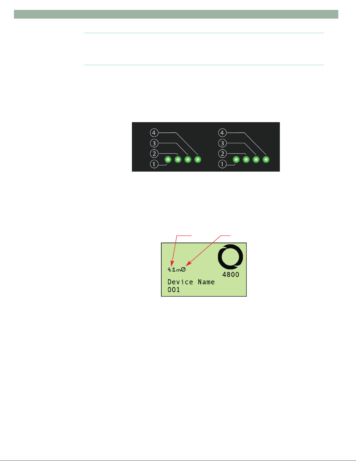
The Activity LEDs on the front panel are positioned in relation to the disk drive bays found
at the top of the enclosure. They are listed numerically from the front to the rear using the
numbers 1-4. The numbers indicate the slot for that column of drives. For example the left
most lower Activity LED (1) is the drive slot 1 in the first column from the left, as viewed
from above. Likewise, in the same column of Activity LEDs the (4) LED is for the fourth or
last drive in the first column from the left of the enclosure, also as viewed from above.
Figure 1-13: Close-up of Front Panel LEDs
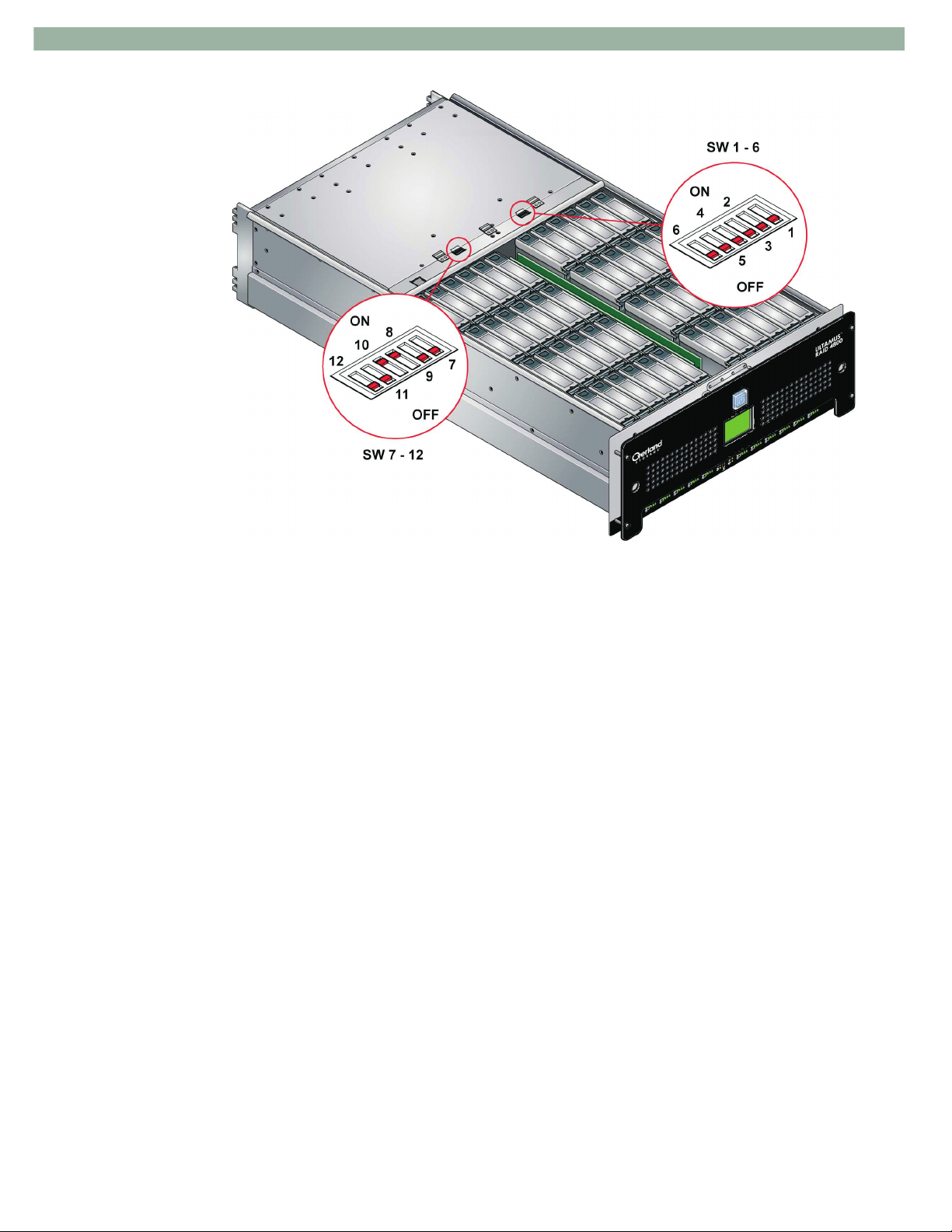
Enclosure Switches
The following switches are mounted on the backplane, located between the drive and rear
module bays. They are only accessible when the enclosure lid is fully open. These switch
settings are only read during the power up cycle.
The two switches are provided for configuring the operating mode of the enclosure. The
switch settings are detailed in Table 2–2 on page 39. The two modes are RAID Chassis and
Expansion Chassis. A switch setting is also provided to mute the audible alarm for all
events.
Enclosure ID Mode
Figure 1-14: LCD Display of the Switch Settings
10400121-101-SG 06/07 W 9
ULTAMUS RAID 4800 Setup Guide Chapter 1
Plug-in Modules
The enclosure requires the following modules for normal operation: Power Supply/Cooling
modules (3), RAID Controllers (2) or EBOD I/O modules (2), and an ACRS module (1).
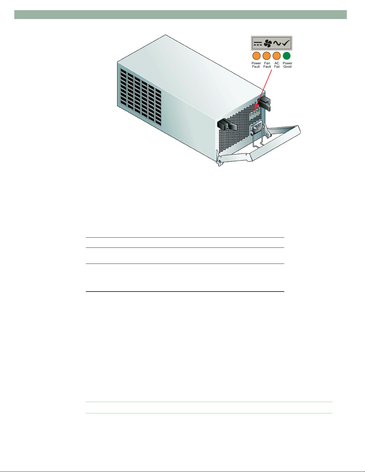
Power Supply/Cooling Module
Three auto ranging AC 450W Power Supply/Cooling modules are supplied mounted at the
rear of the enclosure as part of the core product. The Power Supply/Cooling module
operating voltage range is 100 - 240V, and is selected automatically. When used with the
optional ACRS module and bifurcated power cables, it must operate at a reduced range of
200 - 240V.
Note: If the optional ACRS module is not utilized, either 110V or 240V must be applied to
all three Power Supply/Cooling modules.
Under normal operations, all three power supplies are providing power to the chassis. In
this situation, all three power supplies share the load equally. Show a power supply fail,
thee two remaining power supplies continue to share the load. This of course assumes that
there was power being applied to all three power supplies.
Figure 1-15: Enclosure Switches
10 X 10400121-101-SG 06/07
ULTAMUS RAID 4800 Setup Guide Chapter 1
Figure 1-16: Power Supply/Cooling Module LEDs
Four LEDs are mounted on the front panel of the Power Supply/Cooling module and
indicate the status of the power supply and cooling fans (see Table 1–3).
Table 1–3: Power Supply/Cooling Module LEDs
LED Status
Power Good AC Fail
Fan Fault Power Fault
Power supply and fan are operating
normally. (Green)
Cooling fan failure within the module or
the storage system is in STANDBY
mode (Power On/Standby button set to
standby). (Amber)
Under normal operations, all three power supplies are providing power to the chassis. In
this situation, all three power supplies share the load equally. Should a power supply fail,
the two remaining power supplies continue to share the load. This of course assumes that
there was power being applied to all three power supplies.
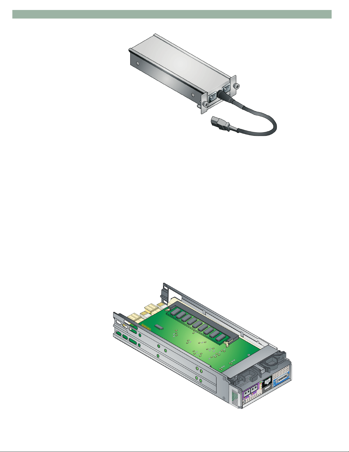
ACRS Module (Optional)
If installed, the function of the ACRS (AC Redundant Switch) is to provide failover of mains
supply in the event one power source fails. If such a failure occurs, the circuitry will ensure
that there is no disruption to the system.
The optional ACRS module is a stand-alone module (available separately) with no internal
connectors and is installed in the center module bay at the rear of the enclosure. The
module includes two Input IEC 320 plugs and one Output IEC 320 socket.
AC input failure, indicating a possible loss
of AC power being supplied. (Amber)
Power supply DC output failure. (Amber)
Caution: If utilized, the ACRS only operates at a voltage input range of 200 - 240V.
10400121-101-SG 06/07 W 11
ULTAMUS RAID 4800 Setup Guide Chapter 1
Figure 1-17: Optional ACRS Module
Note: Most of the cabling diagrams depict the use of the ACRS module.
When an ACRS is not utilized, the user should ensure that all three power supplies are
powered by individual power cords (either 110V or 240V). If one of the power supplies fails,
the remaining two pick up the load. However, unless all three power cords are powered by
different mains, there is no protection against the loss of power to the mains supply that
affects more than one power supply/cooling module.
When an ACRS is utilized, it is meant to be used with two independent 200 - 240V power
mains or phases. In the event one of the power sources fail, the ACRS along with the
bifurcated (or four individual) power cables, ensures that mains power is routed to all
power supply/cooling modules. In the event that both power mains remain good, but a
power supply fails, power is still applied via the bifurcated or individual power cables and
the two remaining operational power supplies.
RAID Controller Module
The ULTAMUS RAID 4800 enclosure houses two RAID Controller modules shown in
Figure 1-18.
Figure 1-18: RAID Controller Module (Shown Upside Down)
12 X 10400121-101-SG 06/07
ULTAMUS RAID 4800 Setup Guide Chapter 1
The plug-in RAID Controller modules have been designed for integration into the
enclosure, utilizing Fibre Channel interconnections with the host computer system and a
SAS expansion port. It supports 512 MB or 1GB cache memory configuration.
The backplane circuit board incorporates connections to each of the SAS ports within the
RAID Controller modules.
Processors housed on the RAID Controller modules provide enclosure management and
interface to devices on the Baseplane, Power Supply/Cooling module, SAS-SATA Channel
cards and EIP card to monitor internal functions. These processors operate in a dual active
configuration to allow for failover and failback.
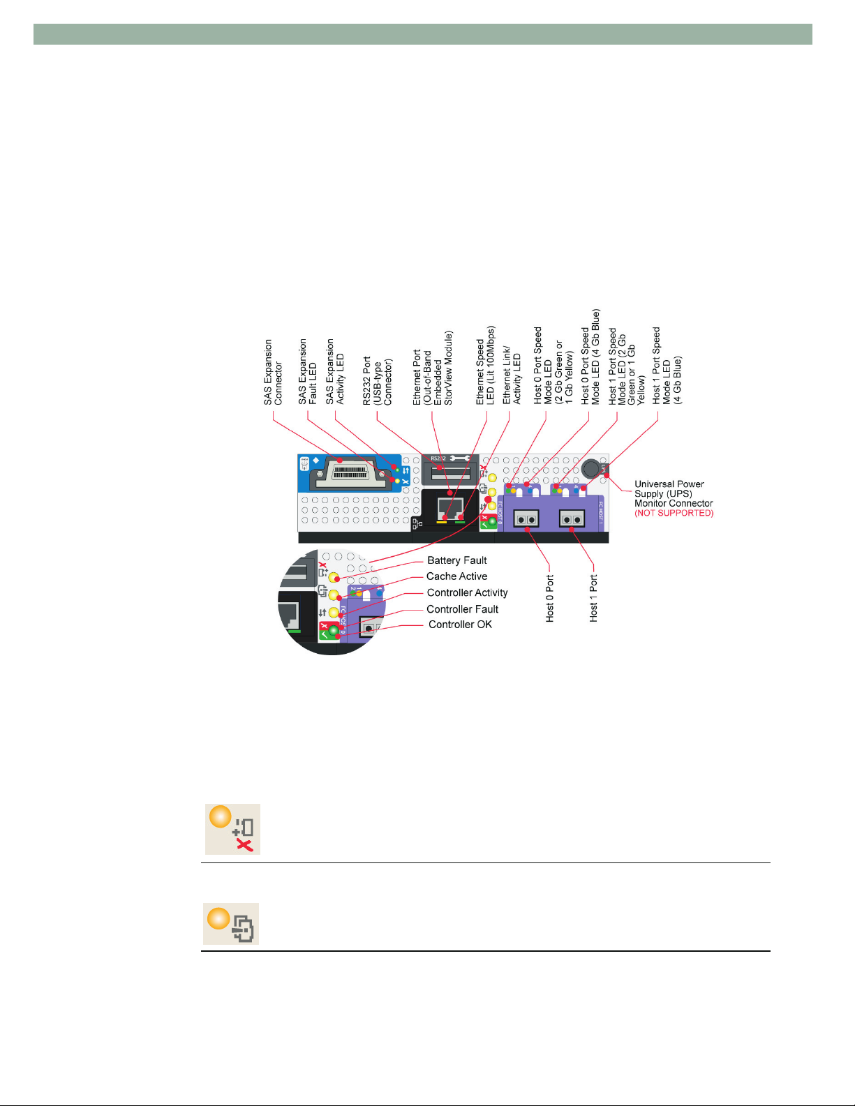
The module incorporates LED indicators, shown in Figure 1-19. Refer to Table 1–4 for
details of the LED status conditions.
Figure 1-19: RAID Controller Module Front Panel
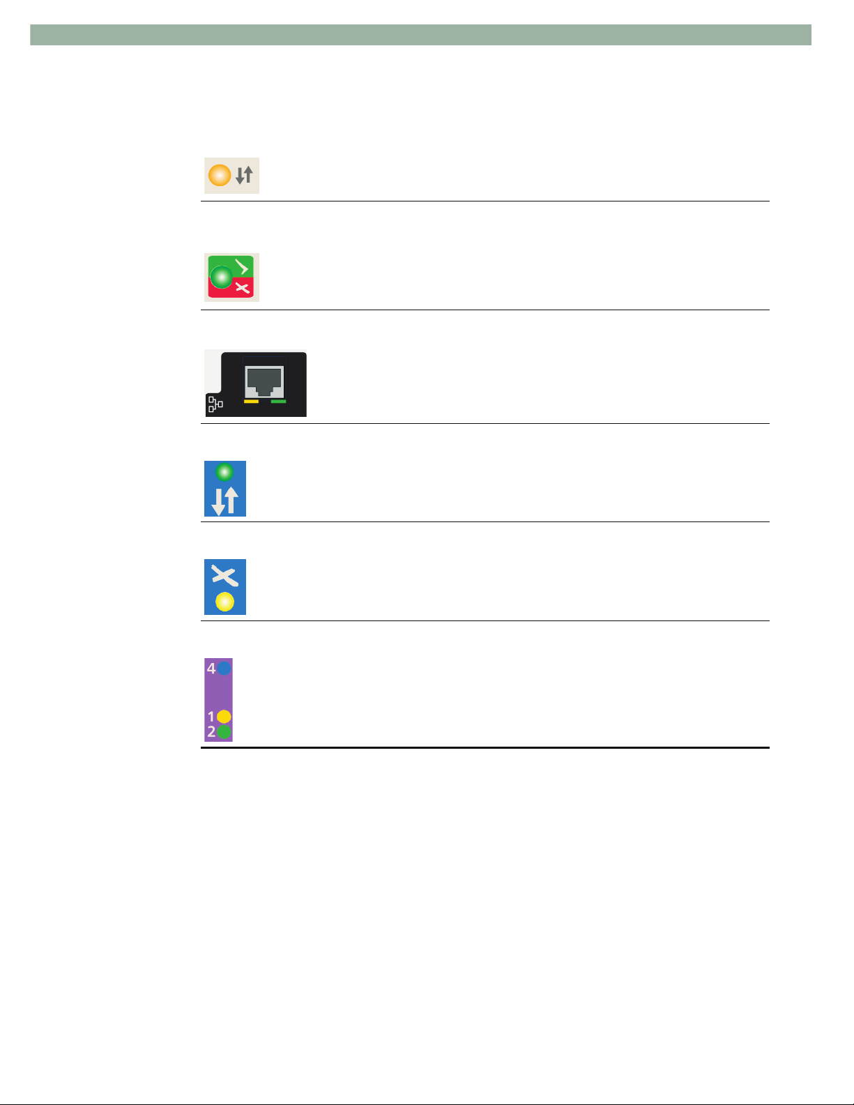
Table 1–4: RAID Controller Module - LED & Icon Status Descriptions
LED/Icon Description
Battery Fault This LED/icon appears adjacent to the controller’s Ethernet and host FC
ports.
Illuminated - A fault has occurred in the backup battery module. It may be a
faulty battery, a charger failure, or the battery may be charging. To determine
if a fault exists, refer to the event logs.
Cache Active This LED/icon appears adjacent to the controller’s Ethernet and host FC
ports.
Illuminated - RAID Controller cache has data saved in memory but not yet
written to the disk array.
10400121-101-SG 06/07 W 13
ULTAMUS RAID 4800 Setup Guide Chapter 1
Table 1–4: RAID Controller Module - LED & Icon Status Descriptions (Continued)
LED/Icon Description
Controller Activity This LED/icon appears adjacent to the controller’s Ethernet and host FC
Controller OK/Fault This LED/icon (bi-color: green/amber) appears adjacent to the controller’s
Ethernet Link/Status These LEDs appear adjacent to the controller’s Ethernet port.
SAS Expansion Activity This LED/icon appears adjacent to the SAS connector.
SAS Expansion Fault This LED/icon appears adjacent to the SAS connector.
ports.
Illuminated - RAID Controller activity is occurring.
Ethernet and host FC ports.
Illuminated Green - RAID Controller operation is normal.
Illuminated Amber - RAID Controller fault has occurred.
Green - Ethernet port has a link connection and link activity.
Yellow - Ethernet port speed. When illuminated it indicates the port is running
at 100 Mbps and when Off 10 Mbps.
Illuminated - Activity on the SAS expansion port.
Illuminated - A fault on the SAS expansion port.
Host 0/1 Port Speed These LEDs appear adjacent to the Fibre Channel host connectors.
Illuminated - Indicates the speed of the connection.
Amber (1) = 1 Gbit/sec
Green (2) = 2 Gbit/sec
Blue (4) = 4 Gbit/sec
The RAID Controller module has the following external ports.
• Two external (Host) ports that allow for the installation of Small Form Factor Pluggable
(SFP) modules, with auto-bypass at the output. Either or both of these SFP ports can be
used to provide connections to the Host controllers. Each host port operates at 4 Gbit/sec,
giving an effective speed of 8 Gbit/sec; these ports are also backwards compatible with 2
Gbit/sec hosts.
• A SAS expansion port provides for disk expansion utilizing a RS-4835-E3-XPN
enclosure via a SFF-8470 connector.
• A RJ-45 10/100BASE-T Ethernet port allows the controller to be connected to a network
to enable out-of-band management and monitoring using the Embedded ULTAMUS
RAID Manager software.
• An RS-232 serial interface allowing access to the VT-100 firmware-based RAID
Configuration Utility for configuration and monitoring utility.
14 X 10400121-101-SG 06/07
ULTAMUS RAID 4800 Setup Guide Chapter 1
Caution: The RS-232 port uses a USB-type connector, however do not use a standard USB
cable to attach to this port. It requires a special cable available from your supplier. The
RS-232 port is for Ethernet connections only. Do not connect to a telecommunications
network.
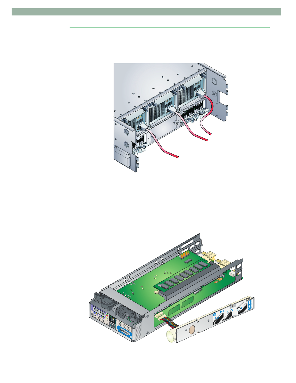
Backup Battery
The RAID Controller module includes a removable backup battery that provides protection
of the cache contents if the AC power fails. The amount of time the data is protected is
available via the software management interface and is a function of the size of the cache.
The battery is a Nickel Metal Hydride battery pack and is serviced as a whole assembly
(field swappable).
Figure 1-20: ULTAMUS RAID 4800 with RAID Modules Installed
Figure 1-21: RAID Controller Backup Battery
10400121-101-SG 06/07 W 15
 Loading...