

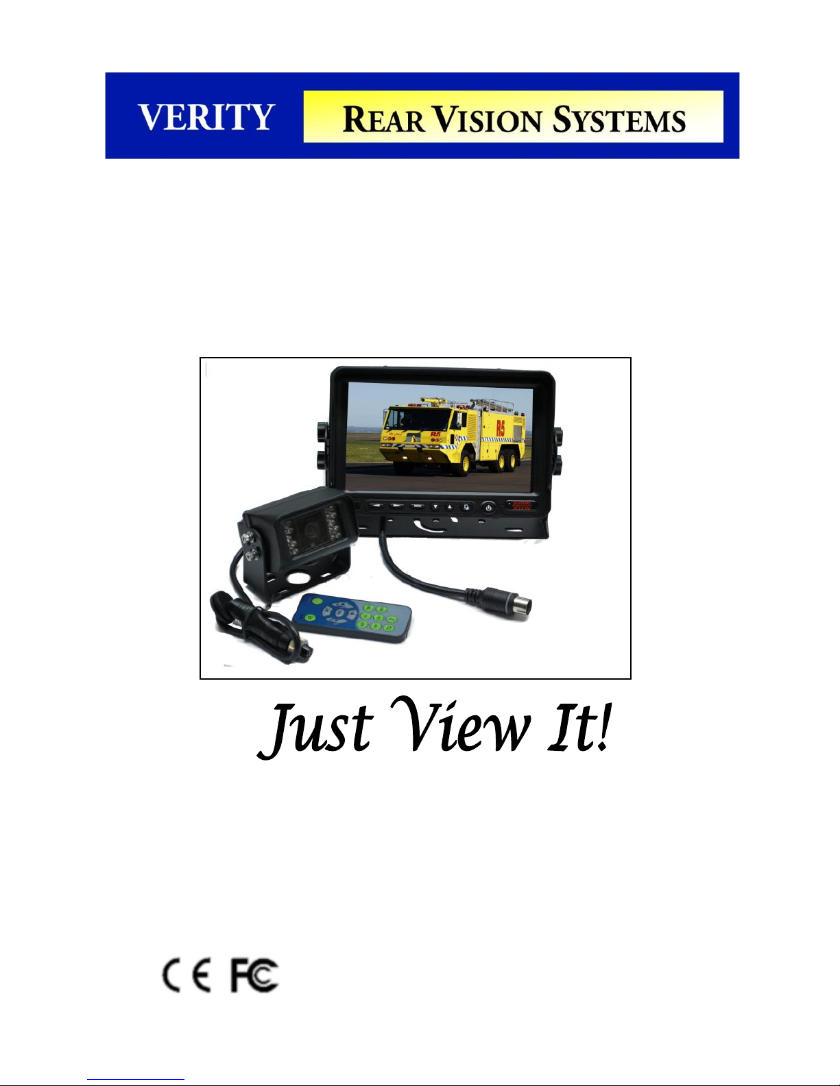
7 INCH DIGITAL
MONITOR SYSTEM
Part # SM07C/
(Part # SMH7C includes ADD23H)
A division of
Component Solution Services, LLC.
56600 Twin Branch Dr.,
Mishawaka, IN 46545
wwwVerityRVS.com
Please read this manual completely before operating the SYSTEM
© 2015 Verity Rear Vision Systems

Component Solution Services LLC., offers the Verity Rear
Vision Systems® to meet any requirements and price point
within the trucking, specialty vehicles, and RV industry.
Verity Rear Vision Systems® is also home to the Supreme
View® line of specialty format systems. Our standard cabled
systems offer unparalleled features into the trucking and RV
industries. Designed for professional drivers, Verity Rear
Vision Systems develops and markets products and
applications to transmit video, audio, and data either
individually or in any and all combinations. The company has
also developed, manufactured, and marketed different kinds
of personal and vehicle video cameras, DVRs, and
accessories for the commercial transportation, fire/rescue,
and marine OEM markets.
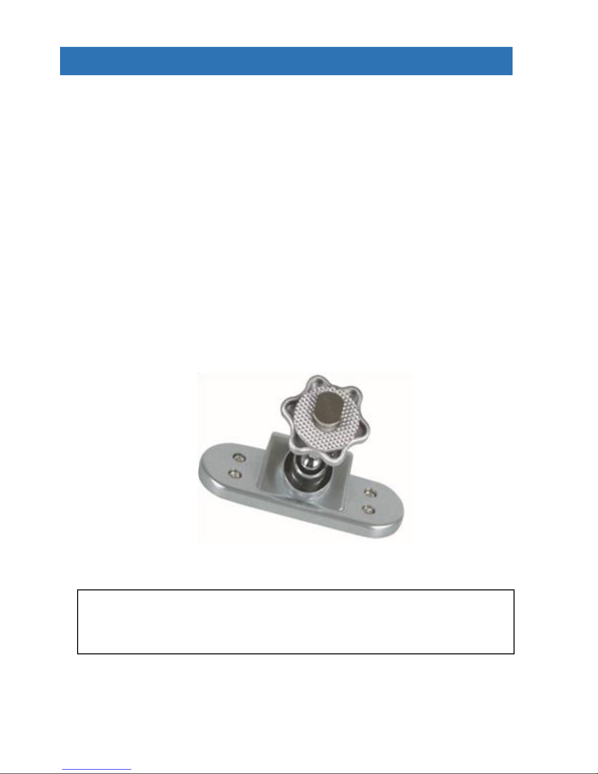
OPTIONAL SLIM-BASED MONITOR MOUNT
For the installs where dashboard real estate is at a minimum
Part Number ADD23H

Think Safety
Read our manual before operating
or installing.
Most likely, your system came preinstalled so the
installation section would be for reference.
Thank you for your purchase of our Verity RVS®. When
installed and used properly, your SM07C is designed to
deliver you years of trouble-free operation. This manual
contains important information required to properly install
and operate the unit. Verity RVS units are designed for
quick installation by trained professionals in proper
installation environments. Our designs are based on
decades of working with vehicle manufacturers.
Verity RVS products are intended to be installed as a
supplement and our observation systems and/or products
are not intended for use as substitutes for rear-view mirror
devices, or for any other standard motor vehicle equipment
which may be required to be installed on vehicles by law.
Verity RVS products promote improving the vehicle
operator’s field of view. Our products are no substitute for
proper defensive driving techniques, observance of traffic
laws, and motor vehicle safety regulations.
Installation Location
It is unlawful in most locals for any person to drive a motor
vehicle equipped with a television viewer/screen located at
any point forward of the back of the driver’s seat (or in any
location that is visible, directly or indirectly) to the driver
while operating the vehicle. Our systems are designed to
be used primarily as a rear observation device.
DO NOT OPEN ANY COMPONENT. There are no
serviceable parts inside any of the components of the
Verity RVS. Opening the product will break the tamper
indicators and void the warranty. Contact our tech support
if a problem should arise 574-807-6002. For faster
response, fill out a service ticket found on our website.
www.verityrvs.com

WARNING
Do not place heavy objects on cables or cover
them with carpet or mats.
Do not place cables where they can be
crushed in any manner.
Our systems are designed as a driving aid.
Watching videos, broadcasts, DVDs and/or any
images other than intended driving assistance
cameras is prohibited.
CAUTION
To avoid damage to the electronic circuit, stop
using this product while doing welding work to
the vehicle and/or trailers.
Never immerse any component in water, and
do not employ spray cleaners. When cleaning,
use a damp lint-free cloth only.
Connect this unit only to other compatible
devices.
Although our products have built-in surge and
cross polarity protection, make sure all cables
are connected properly; improper cable
connections may damage the camera and the
monitor.
Cables should not be allowed to touch hot or
rotating parts, such as the engine, ventilator,
etc.
Do not locate the monitor near heat generating
vents or devices.
Turn off power to the monitor when connecting
the camera.
Monitors are not designed to be waterproof. (Our
SM07F waterproof monitor is the exception).
Exposure to water, such as rain, may damage the
unit.

SYSTEM FEATURES
MONITOR SPECIFICATIONS
Screen size: 7 inch digital screen (16:9)
Long Life High Resolution: 2400 × 480 Pixel (RGB)
System: PAL/NTSC auto per input
Contrast: 400:1 Brightness: 400cd/m2
Power supply: DC 12V~32V with reverse polarity protection
Operation temperatures: -20~70C Storage temperature: -30~80C
3 AV color coded inputs with color coded trigger wires, auto blue screen if no
signal
Features: HD sunshade, headphone jack, auto light sensor dimming for
buttons and LCD screen, LED blue light buttons, high quality Techwell®
processor, in-line waterproof fuse
Easy Use OSD menu function via buttons & remote: reversing image delay
time 0~15s, (for side cameras) Mirror/Normal image, plus horizontal flip per
signal channel (text stays in normal view for readability), multi-language,
1 / 3” COLOR CCD SENSOR SPECIFICATIONS
With Audio and IR
TV System: NTSC
Aluminum shelled waterproof camera with hex bolts for insured positioning
Image Type: 1/3 Inch Color CCD Sharp® or SONY® (no cheap off brands
used)
Horizontal Resolution: 420TV Lines
Effective pixel: NTSC: 510(H) × 492(V)
Illumination: 0 Lux (built-in 10 high output IR LED's for night vision)
Viewing angle: 130°
Waterproof: IP69 Shockproof: 10G
Operating temperature: -40°C to +70°C
Power supply: 12V DC (powered by monitor)

SYSTEM COMPONENTS
I/F Remote
Infrared Weatherproof Camera
20-Meter Camera
“U” Style Mount
13-pin to Monitor Cable
7-Inch Digital Flat

SYSTEM COMPONENTS
This monitor can be mounted on the dash and can be mounted
on both horizontal and vertical surfaces. Make sure the view is
suitable to the driver to observe the images. Take care not to
block any necessary viewing area when mounting. Before
mounting the system, permanently hook up all connections to
ensure proper operation.
Mounting Monitor
1. After determining the monitor location, position the
monitor support bracket, mark the bolt hole location, and then
drill the holes. Be careful not to drill into any other surface that
may be hidden.
2. Attach monitor bracket. Mount the monitor to the support
bracket with supplied 4 angle adjustment screws.
3. Connect one end of the power cable (wire) to the proper
connections. Connect the other end of the power cable (plug)
to the monitor; connect the monitor and the camera with the 13pin system connecting cable.
Camera Connection
Thru-wall Gasket to Seal
Thru Vehicle Exterior
Secondary Waterproof Sleeve
Slides Over Aviation Connection
Waterproof Aviation
Connectors

MONITOR / REMOTE OPERATIONS
1. Remote Signal Receiver Window (Dark Red Box)
Buttons from left to right
2. (VOL-) Volume Decrease Left Arrow
3. (VOL+) Volume Decrease Right Arrow
4. Menu Control Button
5. Down (move down in menu)
6. Up (move Up in menu)
7. (CA1 - CA3) Switches between cameras
8. Power Off/On button - Red color is stand-by- Green is powered
Monitor will turn on if trigger wire activated
VOLUME
INCREASE
MUTE
MENU
VOLUME
DECREASE
POWER
PICTURE
MODE
SWITCH
CAMERA
SETTING DISPLAY
LANGUAGE
FLIP
HORIZONTAL
FLIP VERTICAL
MENU Options
Control Buttons
TIMER

CONNECTION OPERATIONS
VerityRVS Wire Connection Key
4-pin camera connectors
White -Camera 1 rear (Yellow 4-pin)
Blue -Camera 2 right side (Red 4-pin)
Brown -Camera 3 left side (Black 4-pin)
Red wire to key-on hot (+) 10-32v. DC (fused)
Black wire to GND. (-)
White wire to positive Back-up light
Blue wire to positive power Left turn signal
Brown wire to positive power Right turn signal
BE SURE TO ALIGN 13 PIN CONNECTION
If force is applied to this connection when not aligned, it may
damage plug pins and void the warranty.
CAM 1
CAM 2
CAM 3
13-Pin female
4-Pin Female
VerityRVS
Camera Part # C001
VerityRVS
65’ Cable Part # CB020
13-Pin male

MENU OPERATIONS
1. Picture 2. Image Orientation 3. Image Priorty
4. Trigger Delay 5. Language 6.System Setup
The folowing are examples of how the menus work.
1. PICTURE:
Brightness, Contrast, Saturation, and Hue displays
on screen. Brightness, Contrast, Saturation have a
value of 1-100 and Hue has a value of 1-50.
2. Image Orientation:
Flips each camera image individually both
hortizontally and vertically. Allow for correct image of
interior cameras.
CAM 1(N/LR)
Brightness IIIIIIIIIIIIIIIIIIIIII
……………………..
◄ 50 ►
Contrast IIIIIIIIIIIIIIIIIIIIII
……………………..
◄ 50 ►
Saturation IIIIIIIIIIIIIIIIIIIIII
……………………..
◄ 50 ►
Hue IIIIIIIIIIIIIIIIIIIIII
……………………..
◄ 0 ►
CAM 1(N/LR)
► CAM 1 ◄ N -LR ►
CAM 2 ◄ N -LR ►
CAM 3 ◄ N -LR ►

MENU OPERATIONS
3. Reverse Priority: The default priority camera is
CAM 1 in priority order of Cam 1 ► Cam 2 ►Cam
3. If camera CAM 2 is selected as the priority
camera, the order is Cam 2 ► Cam 1► Cam 3. If
camera CAM 3 is selected as the priority camera, the order is
Cam 3► Cam 1► Cam 2.
4. Camera Time Delay (Can be used to program
camera switching time delay. Note due to DOT
laws, the rear camera on less than 10,000 GVWR
cannot have less than a 2 second delay. Thus rear
cameras must have a zero time delay.
CAM 1(N/LR)
CAM Priority ◄ CAM 1 ►
CAM 1(N/LR)
CAM 1
……………………………………………..
◄ 0S ►
CAM 2
……………………………………………..
◄ 0S ►
CAM 3
……………………………………………..
◄ 0S ►

5. LANGAUGE The default language is English along
with 11 options: English, Chinese, French, Deutsch,
Italian, Spanish, Portuguese, Russian, Danish, Polish,
and Dutch.
6. SYSTEM SETTINGS Note: When there is no
power to the monitor, the system screen is black.
When on, the image will only show on channels that
have a camera attached to them. All other camera
channels will be blue by default setting. This can be changed from
blue to black screen. However, it is suggested to leave screen set
to blue. This will allow the user to see a blue screen if the camera
were to get damaged.
Auto Brightness is the option of auto dimming the image for night
driving.
Ruler Line is the turning on and off of the guide lines. Note these
lines are for reference only and do not indicate any specific
measurements. When “ON”, the line stays on. When “Trig” is the
setting, the line will appear when the camera is triggered on. When
“Off”, no line at all will appear.
MENU OPERATIONS
CAM 1(N/R)
Language
◄ English ►
CAM 1(N/R)
Blue Screen
◄ ON ►
Brightness ◄ ON ►
Ruler ◄ TRIG ►

SYSTEM DEMENSIONS
RVS

Verity Rear Vision Systems
A division of
COMPONENT SOLUTION SERVICES (CSS)
LIMITED ONE (1) YEAR WARRANTY
1. CSS products’ warranties are not transferable. The warranties apply to the
retail consumer for one (1) year and covers against defects in material and
workmanship.
2. Defective components will be replaced or repaired, based on a CSS
evaluation of the component. In-bound shipping charges, based on the CSS rate
allocated in the RMA (returned merchandise agreement), will be covered once
the component has been deemed defective at the CSS warranty facility. The
pre-assigned in-bound freight will be supplied upon return of product. All
repaired/replaced warranty parts shall be for the remaining duration of the
original warranty time period.
3. CSS takes pride in our products and will aid in the processing of your
components:
a) All warranty claimants must have consulted our technical support department
for trouble shooting and the acquiring of an RMA. Contact can be made via
email at tech@verityrvs.com or call 574-807-6002.
b) When the warranty claim is made, the consumer must establish the warranty
start dates by presenting documentation regarding the date of retail purchase
(e.g., bill of sale). c) Service performed by non-authorized service personnel
may void all warranty claims.
d) CSS will make no payments for system removal / system re-installing, mileage
allowance, or transportation expenses.
The limited warranty does not cover damage resulting from misuse, accident,
modification or alteration to hardware or software, tampering, unsuitable physical
or operating environment beyond product specifications, improper maintenance,
or failure caused by a product for which CSS is not responsible. There is no
warranty for any product with removed or altered identification labels. CSS
DOES NOT PROVIDE ANY OTHER WARRANTIES OF ANY KIND,
INCLUDING, BUT NOT LIMITED TO, THE IMPLIED WARRANTIES OR
CONDITIONS OF MERCHANTABILITY AND FITNESS FOR A PARTICULAR
PURPOSE. SOME JURISDICTIONS DO NOT ALLOW THE LIMITATION OF
IMPLIED WARRANTIES, SO THIS LIMITATION MAY NOT APPLY TO YOU.
4. This warranty gives you specific legal rights, and you may also have other
rights that vary from state to state.

Technical Support
A service ticket can be filled out on line to supply the quickest
service. The service ticket can be easly found on our web site
www.verityrvs.com or use the code to the right. Please have the
serial number of the system which is found on the back of the
monitor when contacting the service
department. We take great pride in delivering
the most dependable product in the industry.
Each item was 100% QC tested and then we
randomly recheck another up to 10% before it
leaves our hands to you. We have a .034%
issue rate with this product.
Email Tech Support: Tech@verityrvs.com
Phone Tech Support: 574-807-6002
Note: if you are a fire/rescue customer in need of tech support
after hours or on weekends, leave a message and a technician will
return your call as soon as one becomes available.
a division of
Component Solution Services
56600 Twin Branch Drive
Mishawaka, IN 46545
574-807-6002
Toll Free 844-875-4799
We at Verity Rear Vision Systems would like to
personally thank you for purchasing our
product. Our company strives to supply the
best products at a fair price. We care that you
enjoy a safe driving experience.
© 2015 Verity Rear Vision Systems
 Loading...