

VERITAS Access 3340 Installation Manual

Veritas Access 3340 Appliance Hardware Installation Guide

Veritas Access 3340 Appliance Hardware Installation
Guide
Last updated: 2018-03-05
Legal Notice
Copyright © 2018 Veritas Technologies LLC. All rights reserved.
Veritas and the Veritas Logo are trademarks or registered trademarks of Veritas Technologies
LLC or its affiliates in the U.S. and other countries. Other names may be trademarks of their
respective owners.
This product may contain third-party software for which Veritas is required to provide attribution
to the third party (“Third-party Programs”). Some of the Third-party Programs are available
under open source or free software licenses. The License Agreement accompanying the
Software does not alter any rights or obligations you may have under those open source or
free software licenses. Refer to the Third-party Legal Notices document accompanying this
Veritas product or available at:
https://www.veritas.com/about/legal/license-agreements
The product described in this document is distributed under licenses restricting its use, copying,
distribution, and decompilation/reverse engineering. No part of this document may be
reproduced in any form by any means without prior written authorization of Veritas Technologies
LLC and its licensors, if any.
THE DOCUMENTATION IS PROVIDED "AS IS" AND ALL EXPRESS OR IMPLIED
CONDITIONS, REPRESENTATIONS AND WARRANTIES, INCLUDING ANY IMPLIED
WARRANTY OF MERCHANTABILITY, FITNESS FOR A PARTICULAR PURPOSE OR
NON-INFRINGEMENT, ARE DISCLAIMED, EXCEPT TO THE EXTENT THAT SUCH
DISCLAIMERS ARE HELD TO BE LEGALLY INVALID. VERITAS TECHNOLOGIES LLC
SHALL NOT BE LIABLE FOR INCIDENTAL OR CONSEQUENTIAL DAMAGES IN
CONNECTION WITH THE FURNISHING, PERFORMANCE, OR USE OF THIS
DOCUMENTATION. THE INFORMATION CONTAINED IN THIS DOCUMENTATION IS
SUBJECT TO CHANGE WITHOUT NOTICE.
The Licensed Software and Documentation are deemed to be commercial computer software
as defined in FAR 12.212 and subject to restricted rights as defined in FAR Section 52.227-19
"Commercial Computer Software - Restricted Rights" and DFARS 227.7202, et seq.
"Commercial Computer Software and Commercial Computer Software Documentation," as
applicable, and any successor regulations, whether delivered by Veritas as on premises or
hosted services. Any use, modification, reproduction release, performance, display or disclosure
of the Licensed Software and Documentation by the U.S. Government shall be solely in
accordance with the terms of this Agreement.
Veritas Technologies LLC
500 E Middlefield Road
Mountain View, CA 94043

http://www.veritas.com
.
Technical Support
Technical Support maintains support centers globally. All support services will be delivered
in accordance with your support agreement and the then-current enterprise technical support
policies. For information about our support offerings and how to contact Technical Support,
visit our website:
https://www.veritas.com/support
You can manage your Veritas account information at the following URL:
https://my.veritas.com
If you have questions regarding an existing support agreement, please email the support
agreement administration team for your region as follows:
CustomerCare@veritas.comWorldwide (except Japan)
CustomerCare_Japan@veritas.comJapan
Documentation
Make sure that you have the current version of the documentation. Each document displays
the date of the last update on page 2. The latest documentation is available on the Veritas
website:
https://sort.veritas.com/documents
Documentation feedback
Your feedback is important to us. Suggest improvements or report errors or omissions to the
documentation. Include the document title, document version, chapter title, and section title
of the text on which you are reporting. Send feedback to:
APPL.docs@veritas.com
You can also see documentation information or ask a question on the Veritas community site:
http://www.veritas.com/community/
Veritas Services and Operations Readiness Tools (SORT)
Veritas Services and Operations Readiness Tools (SORT) is a website that provides information
and tools to automate and simplify certain time-consuming administrative tasks. Depending
on the product, SORT helps you prepare for installations and upgrades, identify risks in your
datacenters, and improve operational efficiency. To see what services and tools SORT provides
for your product, see the data sheet:
https://sort.veritas.com/data/support/SORT_Data_Sheet.pdf

Contents
Chapter 1 Overview .. ............. ..... .................. ..... ............. ..... .................. . 6
Access 3340 compute node and 5U84 storage shelves . .................. ..... . 6
Access 3340 compute node disk drives .......... ..... .................. ............. 7
Access 3340 compute node control panel .......... ..... ............. ..... .......... 8
Access 3340 compute node rear panel .......... .................. ..... .............. 9
5U84 storage shelf drawers and disk drives ..... .................. ..... ........... 11
5U84 storage shelf control panel ............... ..... .................. ..... .......... 12
5U84 storage shelf rear panel .. .................. .................. ..... .............. 14
5U84 storage shelf RAID controller ......... ..... .................. ..... ............. 14
5U84 storage shelf Expansion module ......... ..... .................. ..... ......... 15
Cables and connectors ..... .................. ..... ............. ..... .................. .. 15
Chapter 2 Pre-installation requirements .... .................. .................. . 17
Customer-provided environment and supplies . .................. ................. 17
Storage shelf shipping container contents ......... ..... .................. ..... ..... 18
Compute node shipping container contents .... ..... .................. ..... ....... 19
Dimensions and determining rack locations ............... ..... .................. . 19
Best practices for rack installation .............. ..... ............. ..... ............... 23
Heat dissipation guidelines ..... .................. .................. ..... ............... 24
Cable length verification .......... ..... ............. ..... .................. ..... ......... 25
Prerequisites for IPMI configuration . ..... .................. .................. ..... ... 25
Chapter 3 Hardware installation procedures . .................. ..... ......... 27
Overview ....... .................. ..... .................. ..... ............. ..... ............. 27
Installing a storage shelf .. ..... .................. ..... ............. ..... ................ 28
Installing disk drives into a storage shelf ............ ..... .................. ......... 38
Installing the compute node rack rails .... ..... ............. ..... .................. .. 41
Installing the compute node into a rack ................. .................. ..... ..... 46
Connecting the hardware to two nodes .......... .................. ..... ............ 48
Connecting to the network . ..... .................. ..... ............. ..... ............... 64
Connecting the power cords to the hardware ............ .................. ..... ... 66
Turning on the hardware and verifying operation . ..... ............. ..... ......... 68
Configuring the IPMI port from the Access Appliance shell menu ............ 71
Accessing and using the Veritas Remote Management interface ......... ... 74

Appendix A Configuring the disk space after adding one or
more new Expansion Storage Shelves . ..... ........... 76
Adding the disk space of an Expansion Storage Shelf from the Access
3340 Appliance shell menu .. .................. ..... ............. ..... ........... 76
5Contents

Overview
This chapter includes the following topics:
■ Access 3340 compute node and 5U84 storage shelves
■ Access 3340 compute node disk drives
■ Access 3340 compute node control panel
■ Access 3340 compute node rear panel
■ 5U84 storage shelf drawers and disk drives
■ 5U84 storage shelf control panel
Chapter
1
■ 5U84 storage shelf rear panel
■ 5U84 storage shelf RAID controller
■ 5U84 storage shelf Expansion module
■ Cables and connectors
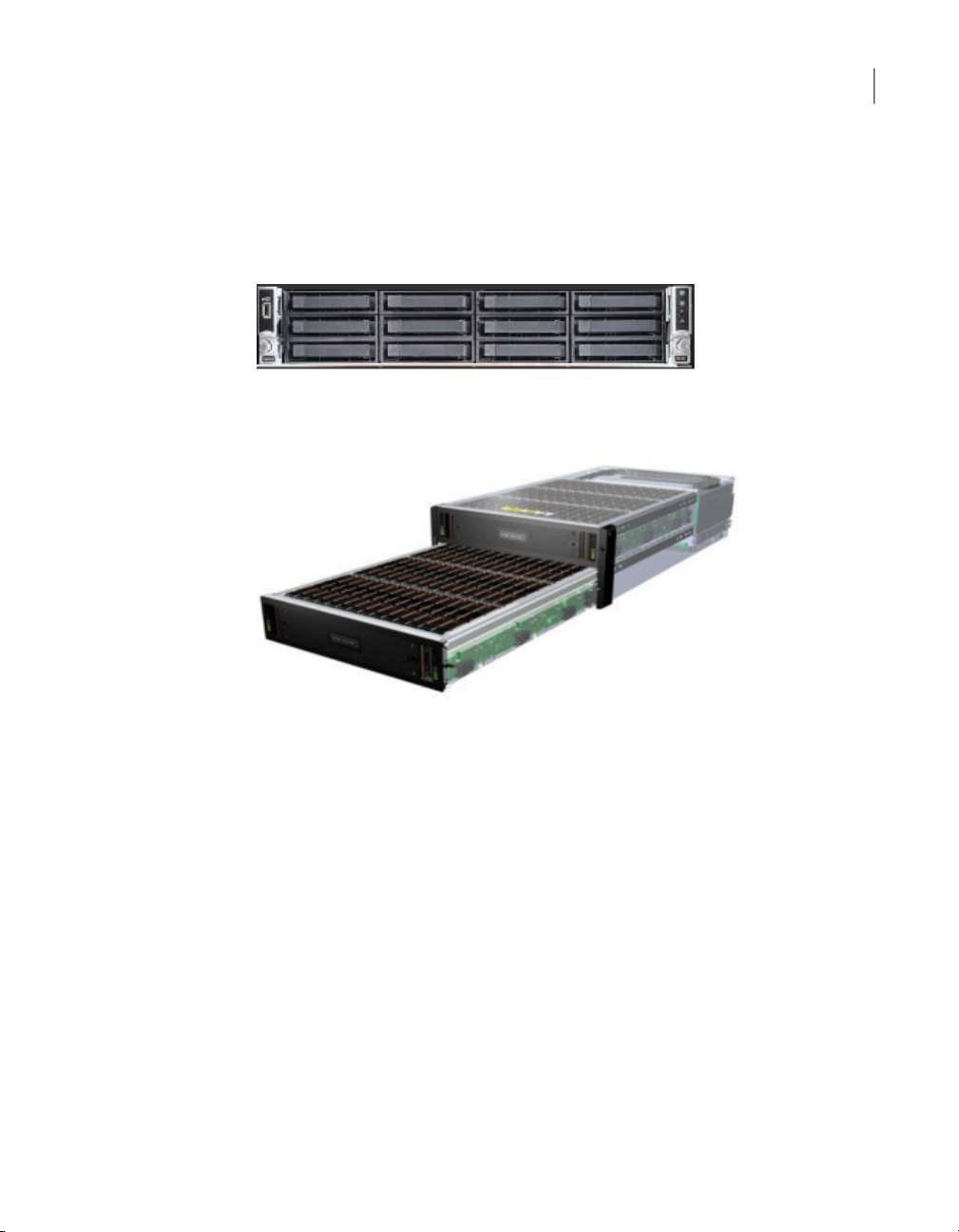
Access 3340 compute node and 5U84 storage shelves
The Veritas 5U84 storage shelves provide storage capacity to the two Access 3340
compute nodes. You must have a Primary Storage Shelf that connects to the
compute nodes. You can use up to three optional Expansion Storage Shelves for
additional storage.
With the required 5U84 Primary Storage Shelf, the compute nodes operate at 220
VAC at 3.1 A with C13 and C14 connectors. The storage shelves require 200 - 220
VAC at 6.67 A with C19 and C20 connectors.
Access 3340 compute node disk drives
Before you install the hardware, refer to the following section for important details
about the dimensions of the hardware.
See “Dimensions and determining rack locations” on page 19.
Each compute node is two rack units (2RU) high.
Each storage shelf is 5RU high and contains 2 drawers with 42 disk drive slots per
drawer.
7Overview
The rear of the Primary shelf includes two redundant RAID controller I/O modules.
The controller modules connect the Primary shelf to the compute nodes. Each
module has a SAS3 Expansion port for connection to Expansion Storage Shelves.
The Expansion shelves contain two I/O modules for connectivity to the Primary
shelf and to other Expansion shelves.
Refer to the Veritas Access 3340 Appliance Product Description at the following
site for details about usable storage capacity.
Appliance documentation
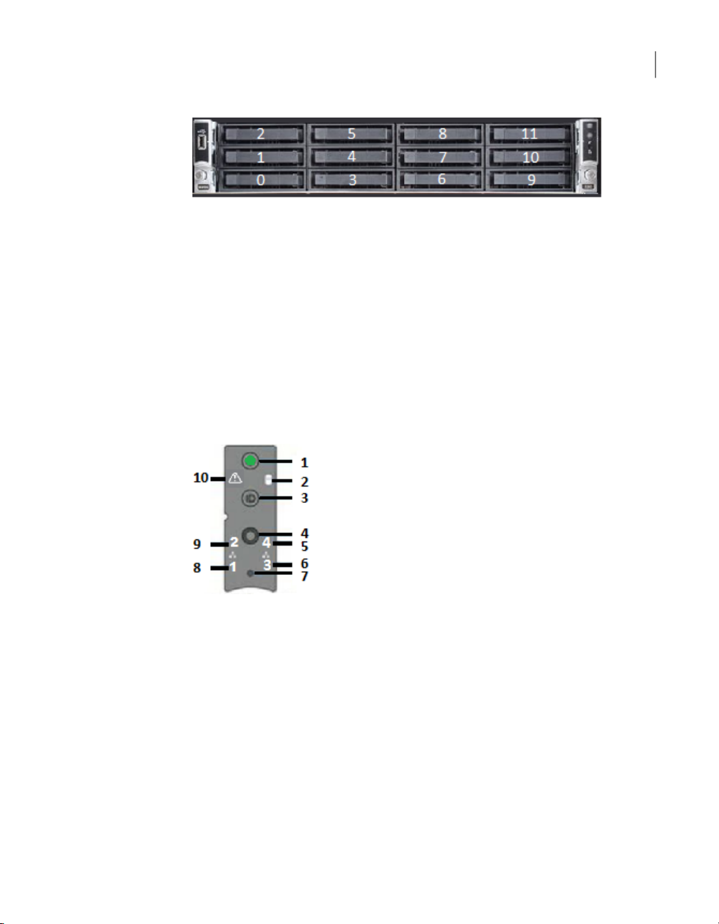
Access 3340 compute node disk drives
The front panel of the compute node contains 12 disk drive slots. The slots are
numbered from zero in the lower left corner to 11 in the upper right corner.
Access 3340 compute node control panel
The disk drive functions are as follows.
■ Slots 0 and 1 - RAID-1 OS volume
■ Slot 2 - hot spare
■ Slots 3 through 11 - blank
The disk drives in the compute node do not provide usable storage capacity.
Access 3340 compute node control panel
A control panel is located on the right front side of the compute node. The following
table describes the components of the control panel.
8Overview
DescriptionComponentNumber
1
3
Power button with
integrated LED
Hard Drive Activity LED2
System ID button with
integrated LED
The System Status LED uses the colors green and
amber to display the health of the compute node.
The drive activity LED on the front panel indicates
drive activity from the on-board hard disk
controllers.
The System ID button toggles on the integrated ID
LED and the blue server board LED and off. The
system ID LED identifies the system for
maintenance when it is racked with similar server
systems.

Access 3340 compute node rear panel
9Overview
DescriptionComponentNumber
4
5
6
8
9
7
System Cold Reset Button
(recessed, tool required)
NIC-4 Activity LED
NIC-3 Activity LED
NIC-1 Activity LED
NIC-2 Activity LED
NMI button (recessed, a
tool is required for use)
System Status LED10
When depressed, the System Cold Reset button
restarts and re-initializes the appliance. Veritas
recommends that you do not use this button.
The NIC LEDs represent a network interface
controller. When network links are detected on the
controllers, the LEDs are activated and remain on.
The LEDs blink when network activity occurs. The
amount of network activity determines the rate of
blinking.
When the NMI button is depressed, the appliance
goes into a halt state, and issues a non-maskable
interrupt (NMI). This feature is useful when you
perform diagnostics for a given issue where a
memory dump is necessary to help determine the
cause of the problem. To prevent an inadvertent
system halt, the NMI button is located behind the
front control panel faceplate. It is only accessible
with the use of a small-tipped tool.
The System Status LED is bi-color indicator that
uses the colors green and amber to display the
current health of the compute node.
Two locations are provided for you to monitor the
health of the system. You can find the first location
on the front control panel. The second location is
located on the back edge of the server board. It is
viewable from the rear of the appliance. Both LEDs
show the same state of health.
Access 3340 compute node rear panel
The rear panel of the compute node contains several components and default ports.
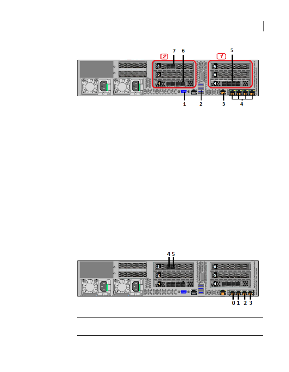
Access 3340 compute node rear panel
The PCIe riser assemblies that are outlined in red are numbered 1 and 2 from right
to left. Slots 1 through 6 are shown in the risers.
The following list describes the numbered items.
1. VGA port
2. Three USB ports
3. IPMI remote management port
4. Four copper, RJ45, 1Gb Ethernet* ports, NIC1/eth0, NIC2/eth1, NIC3/eth2,
and NIC4/eth3, left to right.
5. Riser Assembly 1, Slot 4, contains a SAS3 HBA card that connects to the SAS3
ports on the Primary Storage Shelf.
6. Riser Assembly 2, Slot 1, contains a SAS3 HBA card that connects to the SAS3
ports on the Primary Storage Shelf.
7. One two-port 10GbE network interface card (NIC). From left to right the ports
are NIC5/eth4 and NIC6/eth5.
The following diagram shows the location of the Ethernet ports, from 0 to 5.
10Overview
Note: * The embedded Ethernet ports are copper. PCIe Ethernet ports are fibre.
You cannot bond the copper ports and the fibre ports to each other.
Top drawer, rear
Top drawer, front
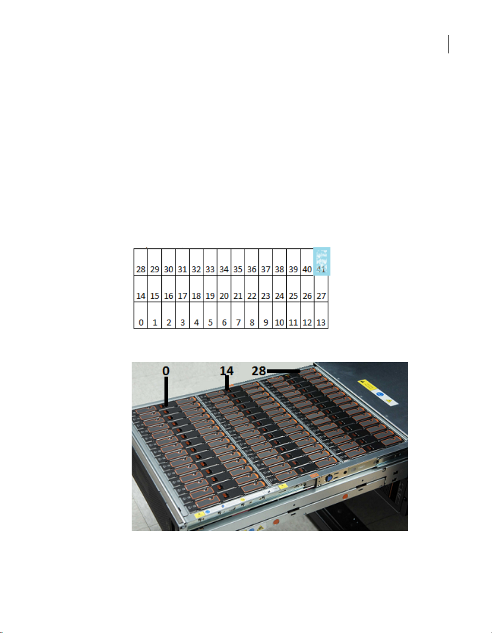
5U84 storage shelf drawers and disk drives
5U84 storage shelf drawers and disk drives
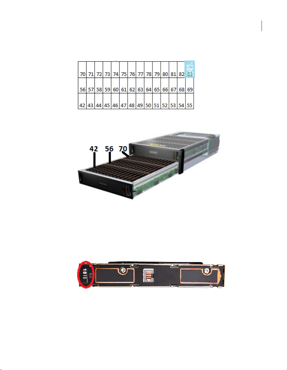
Each storage shelf includes 2 drawers with 42 disk drive slots each for a total of 84
slots. The following diagrams describe the disk layout for the top drawer and the
bottom drawer. The slot numbers start at the front left side of the drawer. Slot
numbers end in the last row at the right rear of the drawer. The top drawer contains
slots 0 through 41. The bottom drawer contains slots 42 through 83.
The following diagrams show all of the slots in each drawer. The photographs show
the number of the first slot in each drawer.
In the top drawer, slot 41 contains a blank carrier instead of a carrier with a disk
drive. The blank carrier is shown in blue.
11Overview
In the bottom drawer, slot 83 contains a blank carrier instead of a carrier with a disk
drive. The blank carrier is shown in blue.
Bottom drawer, rear
Bottom drawer, front
5U84 storage shelf control panel
12Overview
5U84 storage shelf control panel
Disk drives are not preconfigured prior to shipping. Any drive can be placed into
any slot. After you have configured the nodes and storage shelves you cannot move
disk drives to new locations.
Each disk drive is encased in a carrier. A label at the top, front end of the carrier
identifies the storage capacity of the disk that is inside the carrier. Carriers that
contain blanks are labelled "BLANK."
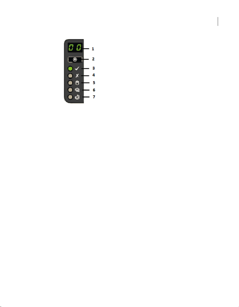
The following table explains the components in the storage shelf control panel.
5U84 storage shelf control panel
13Overview
DescriptionComponentNumber
1
Unit identification
(ID) display
Power LED3
Module fault LED4
Logical status LED5
Drawer 1 fault LED6
Drawer 2 fault LED7
A numerical display that helps when setting up and
maintaining multiple storage shelves. The Primary
shelf has a default value of 00. The first Expansion
shelf has a value of 01. Subsequent Expansion
shelves have a value of 02 and 03.
Used to set the unit identification display.Input switch2
Amber when the system is in standby mode.
Green when the system is on.
Amber when there is a system hardware fault.
An LED may be lit on a power supply, drawer, disk
carrier, cooling module, or I/O module to identify
which component is at fault.
Shows a change of status or a fault. Typically these
changes of status or faults are associated with the
shelf's disk drives. However, the Logical Status
LED can also indicate an issue with an internal
RAID controller or external RAID controller, or with
a host bus adapter.
Indicates a drive, cable, or sideplane fault in Drawer
1, the top drawer.
Indicates a drive, cable, or sideplane fault in Drawer
2, the bottom drawer.

5U84 storage shelf rear panel
The rear panel of a 5U84 storage shelf contains the following components:
■ Two I/O module slots, which contain either redundant RAID controllers or
Expansion modules. (Item 1)
■ Five cooling modules (Item 2)
■ Two power supply units (PSUs) (Item 3)
5U84 storage shelf rear panel
14Overview
Each cooling module contains two fans. Cooling modules can be individually
replaced but cannot be taken apart to replace only one fan.
Refer to the following sections for information about the I/O modules.
See “5U84 storage shelf Expansion module” on page 15.
5U84 storage shelf RAID controller
The Primary Storage Shelf contains two RAID controllers in I/O module slots. The
controllers are labeled A and B, from left to right as you look at the rear panel of a
shelf. Each controller has two sets of SAS3 ports. From left to right the SAS3 ports
for each controller are labeled 3, 2, 1, and 0. The single SAS3 port on the left side
of each RAID controller connects to a SAS3 port on the Expansion shelf.

SAS3 ports
Ethernet
port
A
B C
5U84 storage shelf Expansion module
5U84 storage shelf Expansion module
Each Expansion Storage Shelf contains two I/O modules. The modules are labeled
A and B, from left to right as you look at the rear panel of a shelf. Each module has
three SAS3 ports that are labeled A, B, and C from left to right.
A yellow label states that port B is for attachment to a server only. You cannot use
this port without permission and assistance from Veritas Technical Support.
The SAS3 ports connect to the SAS port on each RAID controller on the Primary
Shelf and to other Expansion Shelves.
15Overview
Cables and connectors
Compute nodes connect to each other with 1G Ethernet cables.
The compute nodes connect to the Primary Storage Shelf with SAS3 cables.
The Primary Storage Shelf connects to Expansion Storage Shelf I/O modules with
SAS3 cables.
Expansion Storage Shelves connect to each other with SAS3 cables.
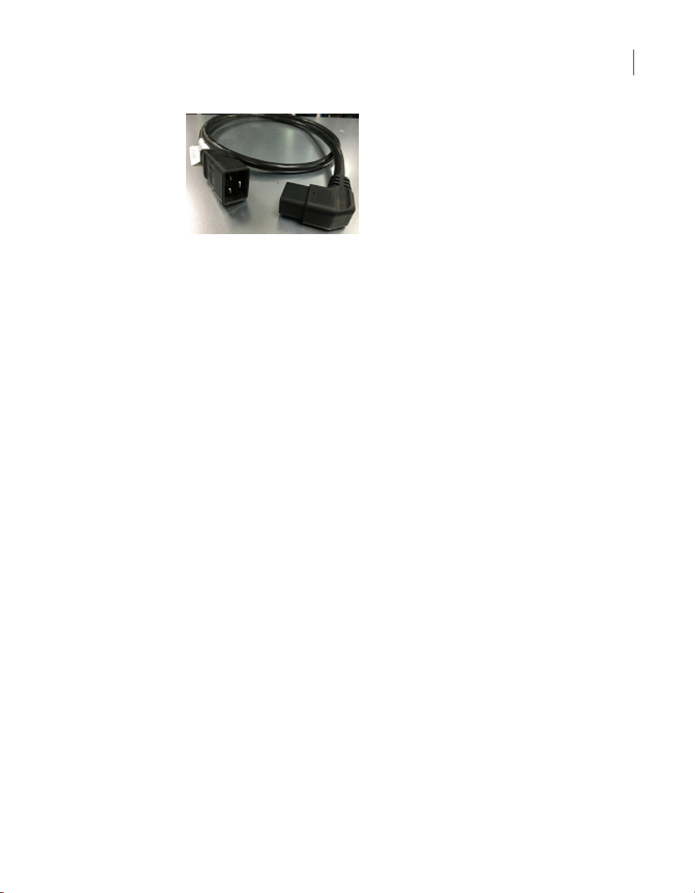
The power connector that attaches to a storage shelf has a right-angled form factor.
Cables and connectors
A security tie assures continued connection between the power cable and the
storage shelf.
16Overview

Pre-installation requirements
This chapter includes the following topics:
■ Customer-provided environment and supplies
■ Storage shelf shipping container contents
■ Compute node shipping container contents
■ Dimensions and determining rack locations
Chapter
2
■ Best practices for rack installation
■ Heat dissipation guidelines
■ Cable length verification
■ Prerequisites for IPMI configuration
Customer-provided environment and supplies
The storage shelf rails can extend from 713mm (28.07in) to 884mm (33.23in) in
length. Be sure that your racks accommodate these rails.
For best ventilation, the rack cabinet:
■ Should be at least 100 cm (4 feet) from walls
■ Should be at least 100 cm (4 feet) from other cabinets on the front and back of
the compute node and the storage shelves
The following list describes the necessary personnel and equipment that are needed
at the installation site:

Storage shelf shipping container contents
■ At least one person or a mechanical lift to move the compute node.
■ Three people or a mechanical lift to move each storage shelf.
■ A magnetic Philips-head screw driver to install the storage shelf rails into the
rack.
■ A Torx T20 screwdriver to lock each of the two drawers in a storage shelf.
■ Cables to connect the compute node to your corporate network.
■ A USB-keyboard and a monitor to connect to the compute node.
■ A 19-inch rack with dual Power Distribution Units (PDUs) with 120VAC or
220VAC power input for the compute node.
■ A 19-inch rack with dual Power Distribution Units (PDUs) with 220VAC power
input for the storage shelves.
Refer to the following section for more details.
See “Heat dissipation guidelines” on page 24.
Storage shelf shipping container contents
18Pre-installation requirements
Each storage shelf container includes other boxes and contents as follows.
■ Open Me First envelope, containing:
■ Deployment plan that provides basic information and links to detailed
information
■ Cable straps
■ Envelope, containing;
■ Warranty agreement
■ Environmental compliance statement
■ Hardware cable connections poster
■ Rack templates
■ Rack rails and mounting hardware
■ Two SAS-3 cables with each Expansion shelf
■ Two power cords
■ One bezel for each drawer
The disk drives ship separately from the storage shelves. Each disk drive shipping
container includes 42 disk drive slots.

Compute node shipping container contents
Each Access 3340 storage disk drive box includes one carrier with a blank. In the
top drawer this blank carrier is inserted into slot 41. In the bottom drawer this blank
carrier is inserted into slot 83.
After you have installed the storage shelves into a rack, you should install the disk
drives into the drawer.
Compute node shipping container contents
Each compute node and each storage shelf is shipped in separate containers. Each
container includes other boxes and contents. The disk drives are installed into the
compute node at the factory.
The following items ship within the compute node box.
Open Me First envelope, containing:
■ Deployment plan that provides basic information and links to detailed information
■ Cable straps
Envelope containing:
■ Warranty agreement
19Pre-installation requirements
■ Environmental compliance statement
■ USB drive with factory image
Hardware such as:
■ Hardware cable connections poster
■ Rack templates
■ Rack rails and mounting hardware
■ Four SAS3 cables
■ Two power cords
■ Bezel
Dimensions and determining rack locations
Physical specifications for the compute node include the following.
■ Each node is two rack units (2RU) high.
■ Node measurements are listed below.
■ Height: 8.89cm (3.5")

Dimensions and determining rack locations
■ Width: 48.26cm (19")
■ Length/depth: 79.38cm (31.25")
■ The compute node rails are extensible to 914mm (36in). This distance is the
maximum depth that is allowed between rack posts.
Physical specifications for the 5U84 storage shelves include the following.
■ Each storage shelf is 5RU high.
■ Storage shelf measurements are listed below.
■ Height: 22.23cm (8.75")
■ Width: 48.26cm (19")
■ Length/depth: 93.35cm (36.75") from the rear of the front flanges to the
extreme rear of the storage shelf chassis.
Note: The 5U84 storage shelf is longer than a standard IEC-compliant rack.
Be sure that your rack cabinet and Power Distribution Units accommodate
the length of the storage shelves.
20Pre-installation requirements
■ The storage shelf rails measure 71.3cm to 88.4cm (28" to 34.8") in length. Be
sure that your rack accommodates this distance from the inside of the front post
to the inside of the rear post. Plan for additional space to accommodate power
strips, power cords, and other cables.
When you plan the installation be sure to allocate enough space for all of the
hardware. A typical installation has the storage shelves on the bottom and the
compute node(s) at the top.
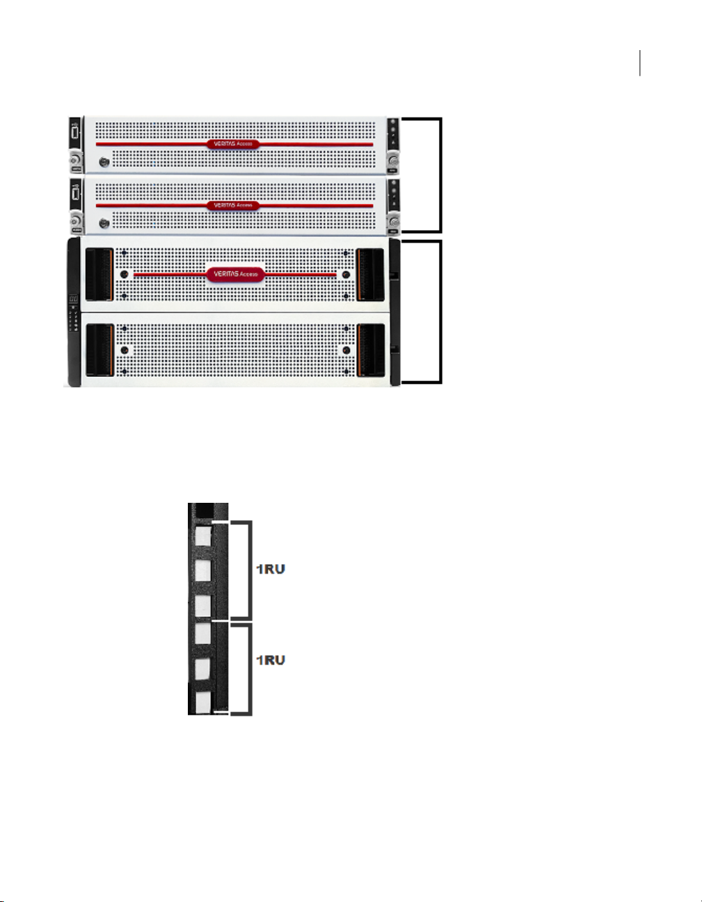
Compute nodes
2RU each
One storage shelf,
two drawers
5RU total
Dimensions and determining rack locations
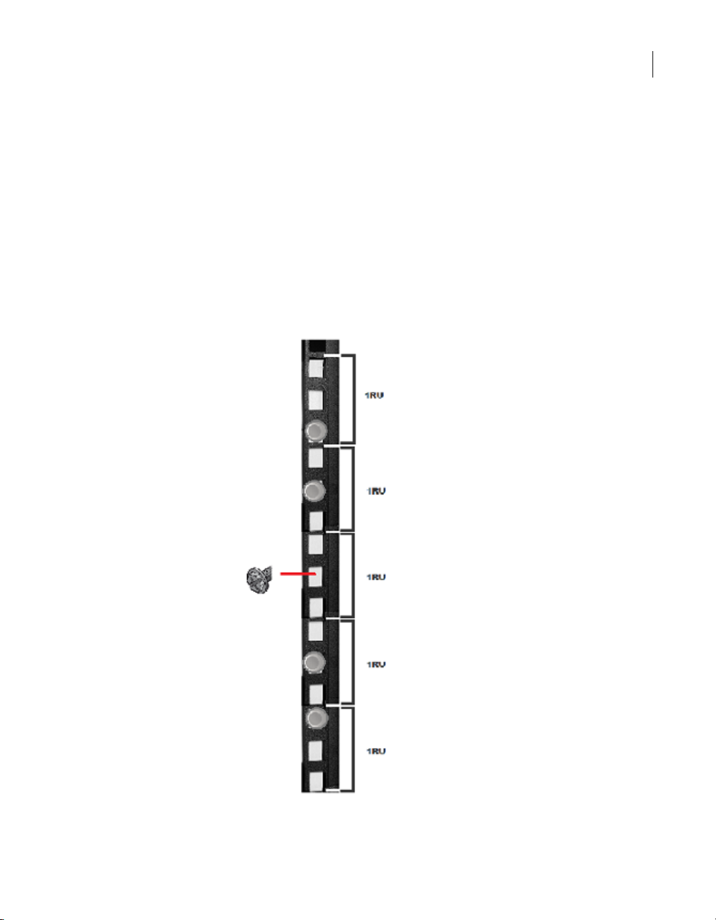
To help you identify RU spacing, many rack manufacturers use a system of lines
and sequential numbers starting at the bottom of the rack. The front and the rear
of the rack are marked the same to ensure that the rails are installed straight and
level. One RU has three holes. The holes for one RU are typically marked with a
line below the bottom hole and another line at the top hole.
21Pre-installation requirements
Use the rack templates to determine the mounting locations for all devices.
To determine rack locations for the hardware
Determine the total number of rack units (RUs) that you need as follows:
1
Dimensions and determining rack locations
■ Two compute nodes (2RU each) and one storage shelf (5RU) require 9RUs
of height in the rack.
■ Two compute nodes (2RU each) and four storage shelves (5RUs) require
24RUs of height in the rack.
Use the rack templates to determine RU locations.
2
Fold the compute node templates at the horizontal yellow lines.
3
Use the following graphics to determine where pins and screws for the storage
4
shelves fit into the rack.
■ The front of each rail includes four pins that insert into the rear of the front
rack post. One screw fits into the middle hole of the middle RU.
22Pre-installation requirements
Best practices for rack installation
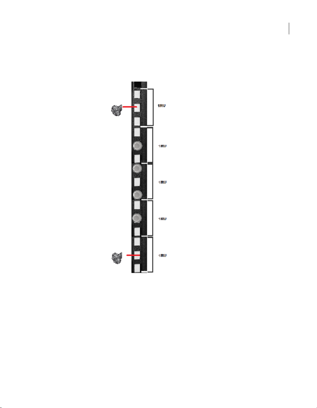
■ The rear of each rail includes four pins that insert into the inside of the rear
rack post. Two screws insert into the front of the rear rack post. The screws
install into the middle hole in the first and the fifth RU.
23Pre-installation requirements
Record the rack positions to help you locate them easily when mounting the
5
hardware.
Best practices for rack installation
Prepare for the hardware installation by following these recommendations.
■ The storage shelves are heavier than the compute node and should be installed
as close to the bottom of the rack as possible.
■ Determine device order and cabling limits.

■ Install one set of rails. Then install the device. Do not install all of the rails at
one time as you may not leave enough room for the devices.
■ Be aware of the depth of the rails and the devices. Ensure that the distance
between cabinet posts accommodates the rails, devices, cables, extending ears,
and PDU strips.
■ Hold a 1m SAS3 cable between the compute nodes and the Primary Storage
Shelf and between the Primary Shelf and the last Expansion Storage Shelf.
Visually confirm that the cables are long enough.
Heat dissipation guidelines
Air flows from the front of each unit and exits from the rear of each unit. You can
install the optional compute node bezel without disruption to the airflow.
For best ventilation, the rack cabinet should:
■ Be at least 100 cm (4 feet) from walls.
■ Be at least 100 cm (4 feet) from other cabinets on the front and back of the
compute node and the storage shelves.
Heat dissipation guidelines
24Pre-installation requirements
Note: Data centers with two-foot spaces in the front and in the back of the compute
nodes are acceptable with proper cooling and ventilation.
The following requirements ensure sufficient cooling to the devices.
■ Veritas requires that you install the devices in a National Engineering
Manufacturer's Association (NEMA)-certified or equivalent rack.
Note: The 5U84 storage shelf is as long as a standard IEC-compliant rack. Be
sure that your rack cabinet and Power Distribution Units (PDUs) accommodate
the length of the storage shelves.
■ A minimum of 3 inches (7.6 cm) of space must be between the front of a compute
node and the cabinet door or other air block.
■ A minimum of 6 inches (15.2 cm) of space must be between the rear of a
compute node and the cabinet rear or other air block.
■ A minimum of 1 inch (2.5 cm) of space must be between the front of a storage
shelf and the cabinet door or other air block.
■ A minimum of 2 inches (5.0 cm) of space must be between the rear of a storage
shelf and the cabinet rear or other air block.
 Loading...