

VERITAS 05M25.01 Instructions Manual

Jointer Blade Sharpener
05M25.01
The Veritas® Jointer Blade Sharpener will jig planer and jointer knives
and hand plane blades up to 8" in width with bevel angles from 25°
to 45°. Sharpening and adding a micro-bevel to wide blades is easy,
repeatable and accurate when using the jointer blade sharpener.
A half sheet of 15 micron, pressure sensitive adhesive (PSA)
backed silicon carbide micro-abrasive is included with your jointer
blade sharpener. Applied to a fl at surface, it will quickly sharpen
jointer blades. However, other abrasive sheets may be used, such
as chromium oxide or diamond. Sharpening may even be done on a
traditional bench stone (see Additional Tips, Using a Bench Stone).
Instructions
Prepare the Lapping Surface
The PSA-backed micro-abrasive sheet must be applied to a fl at
lapping surface. The infeed or outfeed table of your jointer, or a piece
1
/4" (or thicker) plate glass, is recommended. For greater safety,
of
1
we offer a
/4" thick, 81/2" × 14" tempered glass plate (05M20.12).
Thoroughly clean the glass (or other true surface) before applying
the abrasive sheet. If you are applying the sheet to glass, create a
thin fi lm of water on the glass. This allows you to adjust the position
of the sheet before sticking it down. Position the sheet at one end of
the glass plate so that it covers the full width. To prevent air or water
bubbles from becoming entrapped, either roll a dowel or draw the
edge of a piece of wood across the sheet (working from the center)
to bond it in place.
Do not use water to apply the micro-abrasive sheet to steel, cast
iron, or any other rust-prone surface. Instead, to prevent air bubbles
from becoming entrapped, make initial contact with one edge of the
sheet. Progressively lay the sheet down, using a straightedge as a
squeegee.

Lap the Face of the Blade
Since a sharp edge is the
intersection of two smooth
surfaces, the face or
bottom of the blade must
be perfectly smooth in the
area near the cutting edge
before you attempt to hone
the bevel.
Figure 1: Parts of a blade.
Most manufacturers ship
blades with grinding marks
on the face or bottom that,
if not removed, would leave
a series of fi ne saw teeth on
the tool edge. To avoid these
saw teeth, the face of the
blade must be lapped fl at.
Figure 2: Grinding marks on new blades.
Bevel
Bottom
or Face
The easiest way to lap a new blade is on the 15 micron sheet until
the entire width of the leading edge has a consistent lapping pattern
1
with the manufacturer’s grinding marks removed at least
/16" back
from the leading edge of the blade.
Leading edge
lapped flat
Original
grinding marks
1
/16" Min.
Figure 3: Properly lapped face.
2
Clamping Jointer and Planer Blades
Loosen the thumbnuts securing the three clamps on the jointer blade
sharpener. Position the blade with the bevel facing down under the
short legs of the clamps and lightly tighten the thumbnuts. Turn the
unit over and adjust the blade until it overhangs the edge of the jointer
1
blade sharpener body by about
/8" and is approximately parallel as
shown in Figure 4.
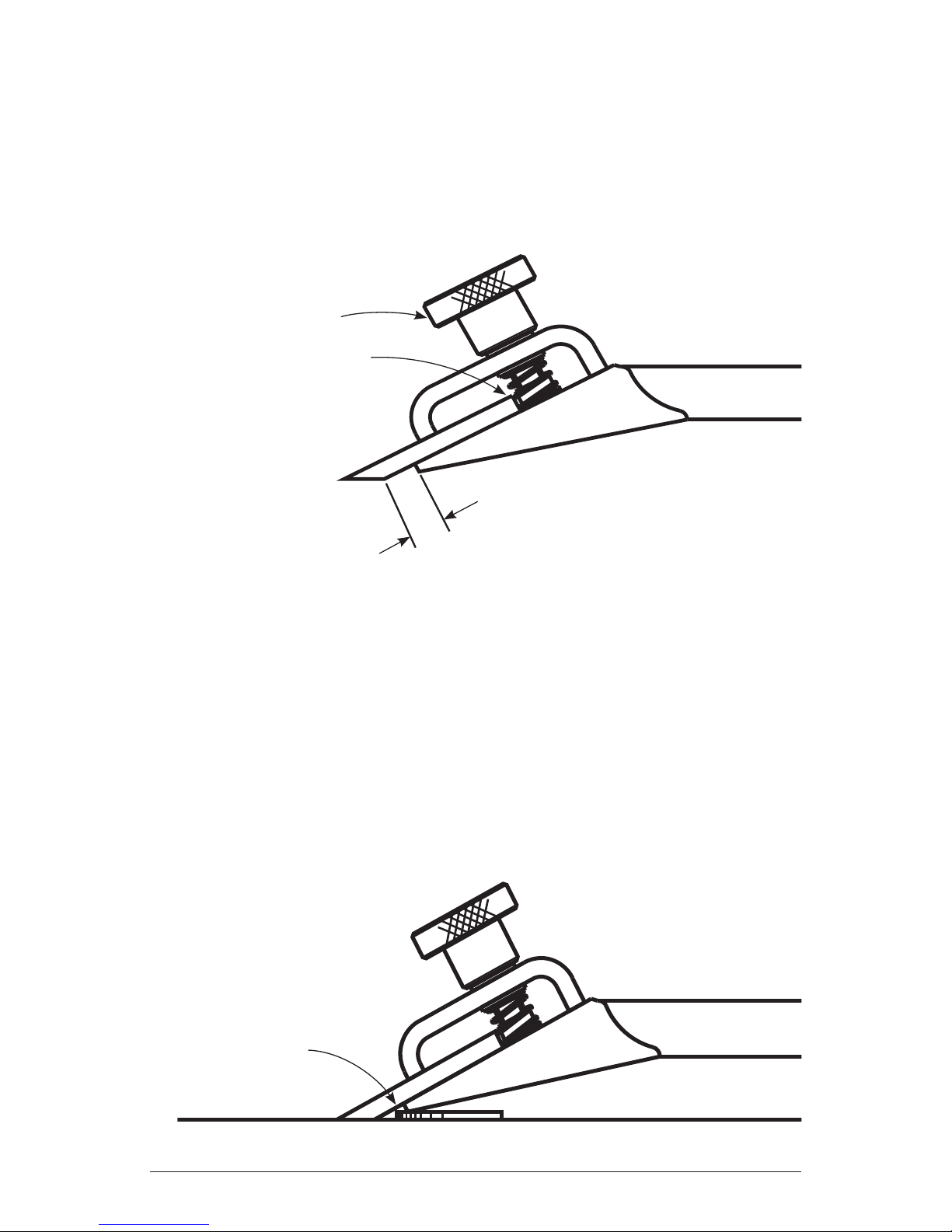
Thumbnut
Note: clamp spring
is touching back
edge of blade
1
/8"
Figure 4: Clamping jointer/planer blades.
Before you fully tighten the thumbnuts, slide them forward until
the clamp springs touch the rear of the blade. This increases the
clamping force, reducing the possibility of the blade shifting during
sharpening (see Figure 4).
Hint: The blade can also be positioned by putting two pennies (one
at each end) under the front of the jointer blade sharpener as it rests
on a fl at surface. Let the bevel of the blade slide down to rest on the
surface, then tighten the thumbnuts.
Penny
Figure 5: Positioning blade using penny method.
3
 Loading...