

VERIS INDUSTRIES, INC. Hawkeye 800 Installation Instructions Manual
Installation Instructions
OPERATION
Hawkeye 800
Solid Core Fixed Threshold
Current Status Switch
INSTALLATION
CAUTION!
• This product is not intended for life or safety
applications.
• Installing sensors in an energized motor control center
or on any energized conductor can be hazardous.
Severe injury or death can result from electrical shock during contact
with high voltage conductors or related equipment. Disconnect and
lock-out all power sources prior to installation.
Applications shown are suggested means of installing sensors, but it is
the responsibility of the installer to ensure that the installation is in
compliance with all national and local codes. Installation should be
attempted only by individuals familiar with codes, standards, and
proper safety procedures for high-voltage installations.
1. Ensure power conductor to be monitored is
disconnected and locked out from the power source!
2. Install the adjustable mounting bracket to the back of the motor
control center. The sensor may be located at any point on the conductor
between the motor and the motor starter.
3. Align to permit the conductor to fit through the hole. Slide the
conductor through the center hole in the sensor and connect the
conductor to the lugs on the motor starter.
Note: Low (<0.5 amp) and high (>200 amp) applications may require
special installation:
a. Low amperage (<0.5 amp FLA) - to provide adequate current,
wrap conductor through the center hole and around the sensor body to
produce multiple turns and increase flow. Measured current = Actual
Current x Number of turns.
b. High amperage (>200 amp FLA) - current flows in excess of
200 amps require the use of an appropriately sized external current
transformer. Install the external CT on the conductor and run the CT
secondary wire through the sensor. CAUTION: CTs can contain
hazardous voltages. Install CTs in accordance to manufacturers’
specifications and instructions.
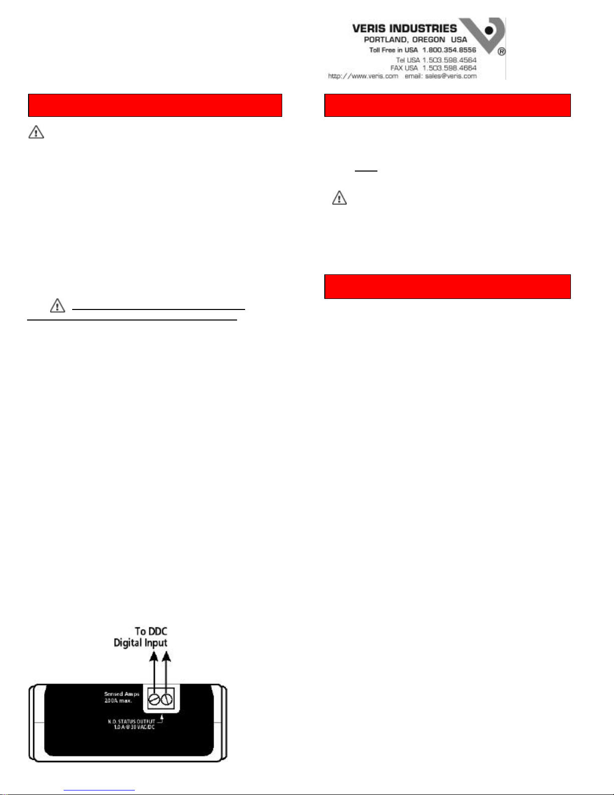
4. Wire as shown below. Note: Testing the solid-state output of this
sensor with a digital ohm meter may yield inaccurate, but relative
readings of switching (i.e., 6 Meg Ohms.) Use an Analog VOM for
readings similar to loop
Status output is not polarity sensitive!
The sensors status output will indicate a “closed” circuit condition
when monitored conductor current exceeds 0.5A. When conductor
current falls to 0A or is interrupted, the sensors status output will
“open”. Note:
Sensor output is unstable below 0.5A.
CAUTION !
Status indicators of this device should not be relied on to
determine whether or not the monitored conductor is connected to
a power source. Doing so may result in injury or death from
electrical shock.
SPECIFICATIONS
Amperage Ratings.........……………0.5 to 200A continuous
Sensor Supply Voltage....Induced from monitored conductor
Isolation.............................................................600VAC rms
Sealing..................................................................N.E.M.A. 1
Temperature range............................…...............-15 to 60
°C
Humidity range.......................….......0-95% non-condensing
Status Output……...........…...........N.O. 1.0A@30VAC/DC
PN Z101984-0B 2/7/2001

REDUCE LABOR
by 30%!
Mention this flyer and receive a FREE VERIS HAT with your
H540 or H548 order.
The H540 & H548 Provide Motor Control
& Status in a Single Labor Saving Device
Using a single circuit the H500 provides direct control
and status of your fractional HP motors.
And that's not all.
• It eliminates forcing multiple devices into small electrical enclosures.
• It replaces traditional conductor mount of a current switch.
• It simplifies low voltage wiring runs and eliminates high
voltage runs.
Applications
N.O. 1.0A@
CURRENT
SWITCH
Amperage Range
(540) 0.25 to 20A continuous
(548) 0.5 to 20A continuous
OUT TO
LOAD
INCOMING
POWER
STATUS
OUTPUT
30VAC/DC
RELAY
LED
Fractional HP Motors
Exhaust Fans
Fan Coil Units
Recirculation Pumps
POWER
SOURCE
Mounting Options
Line
Voltage
Wires
Low Voltage
Wires
CAUTION: Consult instructions
prior to installation
!
STATUS OUTPUT: 1A@30VAC/DC
RELAY COIL: 24VAC/DC; 16mA nom.
RELAY OUTPUT: 16(8)A@250VAC; 3/4 HP
1/2" Conduit
Fitting
VERIS INDUSTRIES, INC.
PORTLAND, OREGON USA
TOLL FREE USA 1.800.354.8556
TEL USA 1.503.598.4564
FAX USA 1.503.598.4664
548
RS
HAND
OC
OFF
AUTO
SO
SP
SC
4S JUNCTION BOX
Status Output & Relay Coil
(Low Voltage Wires)
Nipple to
Existing
Enclosures
RELAY
24VAC/DC
36mA nom.
1/3HP@125VAC
3/4HP@250VAC
HOA
CURRENT
SWITCH
LED'S
EXHAUST FAN
IN SERIES
Low Voltage
Wires
Line Voltage
Wires
VERIS INDUSTRIES, INC.
PORTLAND, OREGON USA
TEL USA 1.503.598.4564
FAX USA 1.503.598.4664
CAUTION: Consult instructions
prior to installation
!
STATUS OUTPUT: 1A@30VAC/DC
RELAY COIL: 24VAC/DC; 16mA nom.
RELAY OUTPUT: 16(8)A@250VAC; 3/4 HP
1.800.354.8556
TOLL FREE USA
548
HAND
OFF
AUTO
VERIS INDUSTRIES, INC.
®
PORTLAND, OREGON USA
TOLL FREE USA 1.800.354.8556
TEL USA 1.503.598.4564
CAUTION: Consult instructions
prior to installation
!
STATUS OUTPUT: 1A@30VAC/DC
RELAY COIL: 24VAC/DC; 16mA nom.
RELAY OUTPUT: 16(8)A@250VAC; 3/4 HP
FAX USA 1.503.598.4664
548
HAND
OFF
AUTO
RS
OC
SO
SP
SC
ENCLOSURE
Line Voltage
Wires
ENCLOSURE MOUNT SINGLE GANG BOX WALL MOUNT
Low Voltage Wires
®
RS
OC
SO
SP
SC
1/2" Conduit
Fitting
MODEL STATUS TRIP POINT
H540
"Go/No"
H548
"Adjustable"
0.25 A
0.5 A
VERIS INDUSTRIES
PORTLAND, OREGON USA
Toll Free in USA 1.800.354.8556
®
 Loading...