

VERIS INDUSTRIES, INC. HAWKEYE 548 Installation Instructions Manual
INSTALLATION
!CAUTION !
• This product is not intended for life or safety
applications
• Installing sensors in an energized motor control
center or on any energized conductor can be hazardous.
Severe injury or death can result from electrical shock
during contact with high voltage conductors or related
equipment. Disconnect and lockout all power sources
during installation. Applications shown are suggested
means of installing sensors, but it is the responsibility of
the installer to ensure that the installation is in compliance with all national and local codes. Installation should
be attempted only by individuals familiar with codes,
standards, and proper safety procedures for high-voltage
installations. Do not rely on status indications of device
exclusively to determine if power is present in conductor.
1. Ensure power conductor to be monitored is disconnected
and locked out from the power source!
2. Hold the sensor by the base and remove the two screws
located at opposite corners of the unit’s cover. Carefully
pull the cover off of the base. Extract the conduit lockwasher
and K.O. seal and set them and the base aside.
3. Connect wiring system to the hole(s) in the sides of the
base to wire the status and command relay connections.
4. Wire the low voltage leads to avoid the load wiring. Use
copper conductors only for command relay and status
outputs. Tighten terminal blocks to 3.5 lb. in. torque.
5. Set the Jumper block for N.O. or N. C. operation, then
select one of the following (a, b, or c) to match your
installation.
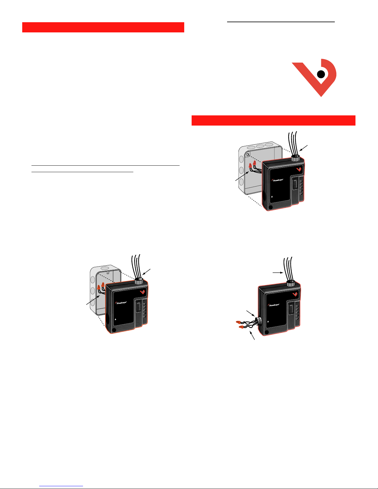
a.)duplex box:
Low Voltage Wires
Installation Instructions
HAWKEYE 548
Solid-State Current Switch
VERIS INDUSTRIES, INC.
10831 S.W. CASCADE BLVD.
http://www.veris.com email:sales@veris.com
INSTALLATION
b.) 4S junction box:
Line Voltage
Wires
1.) Route the two 12 AWG wires through the large hole in
the center of the circuit board. Break the “HOT” lead
to your load and connect these wires to the ends.
2.) Locate the holes through opposite corners of the base.
These holes are used to mount the sensor to the box.
c.) surface mounting:
PORTLAND, OREGON 97223
(503) 598-4564 FAX (503) 598-4664
Low Voltage
Wires
1-800-354-8556
VERIS INDUSTRIES, INC.
PORTLAND, OREGON USA
TOLL FREE USA 1.800.354.8556
TEL USA 1.503.598.4564
FAX USA 1.503.598.4664
548
HAND
OFF
AUTO
CAUTION: Consult instructions
prior to installation
!
STATUS OUTPUT: 1A@30VAC/DC
RELAY COIL: 24VAC/DC; 16mA nom.
RELAY OUTPUT: 16(8)A@250VAC; 3/4 HP
®
RS
OC
SO
SP
SC
Low Voltage
Wires
®
Line Voltage
Wires
VERIS INDUSTRIES, INC.
PORTLAND, OREGON USA
TEL USA 1.503.598.4564
FAX USA 1.503.598.4664
CAUTION: Consult instructions
prior to installation
!
STATUS OUTPUT: 1A@30VAC/DC
RELAY COIL: 24VAC/DC; 16mA nom.
RELAY OUTPUT: 16(8)A@250VAC; 3/4 HP
TOLL FREE USA 1.800.354.8556
548
HAND
OFF
AUTO
®
RS
OC
SO
SP
SC
1.) Route the two 12 AWG wires through the large hole in
the center of the circuit board. Break the “HOT” lead
to your load and connect these wires to the ends.
2.) Hold the base with the circuit board toward you.
Locate the smaller round hole in the circuit board (near
the relay). The hole through the case behind the board
hole, and the slot just above the board are used to
mount the H500 to a duplex (receptacle) box.
PN Z101562 10/8/1998
1/2" Conduit
Fitting
CAUTION: Consult instructions
prior to installation
!
STATUS OUTPUT: 1A@30VAC/DC
RELAY COIL: 24VAC/DC; 16mA nom.
RELAY OUTPUT: 16(8)A@250VAC; 3/4 HP
Line Voltage
Wires
VERIS INDUSTRIES, INC.
PORTLAND, OREGON USA
TEL USA 1.503.598.4564
FAX USA 1.503.598.4664
TOLL FREE USA 1.800.354.8556
548
HAND
OFF
AUTO
®
RS
OC
SO
SP
SC
1.) Use the base as a template to drill mounting holes. Any
of the screw holes in the base may be used to mount
the sensor to wall or device.
2.) Use the side hole (1/2” conduit) near the relay to route
load connections. Break the “HOT” lead to your load
and connect the 12 AWG wires to the ends. Alternately,
cut a hole in the surface of the wall or device to route
the two 12 AWG wires as for the 4S box, above. The cut
hole should be larger than the hole in the base to
avoid chafing the wiring.

CALIBRATION
Note: Testing the solid-state output of this sensor with a
digital ohmmeter may yield inaccurate, but relative readings of
switching (e.g. 6 Megohms.) Use an analog V-O-M for readings
similar to loop values.
1. For under-current status indication: (Belt loss, fan & pump status)
• Turn the set point screw clockwise until the status closed
LED goes out and the status open LED comes on.
• Turn the set point screw counter-clockwise until the status
open LED goes out and the status closed LED comes on.
• Turn the set point screw 1/2 turn counter-clockwise.
• The sensor is now calibrated to provide indication of
current flow below normal full load amps.
Output Status:
Normal: Output closed
Alarm: Output open
2. For over-current status indication: (Locked rotor)
• Turn the set point screw counter-clockwise until the status
open LED goes out and the status closed LED comes on.
• Turn the set point screw clockwise until the status closed
LED goes out and the status open LED comes on.
• Turn the set point screw clockwise 1/2 turn
• The sensor is now calibrated to provide indication of
current flows above normal full load amps
Output Status:
Normal: Output open
Alarm: Output closed
CAUTION!
Status indicators of this device should not be relied on to
determine whether or not the monitored conductor is
connected to a power source. Doing so may result in injury or
death from electrical shock.
For technical assistance, please call 1-800-354-8556
SPECIFICATIONS
Amperage Ratings.........…………........…...0.5 to 20A continuous
Sensor Supply Voltage.........Induced from monitored conductor
Sealing.....................................................................….......NEMA 1
Temperature range.....................................................-15º to 60°C
Humidity range.........................................0-95% non-condensing
Load switching...............................20(6)A@125VAC/30VDC,1/3HP
Relay coil...................................................24VAC/DC; 36mA nom.
Status Output……....................................N.O. 1.0A @ 30 VAC/DC
16(6)A@250VAC,3/4HP
 Loading...