

VERIS INDUSTRIES, INC. E50H2A, E50H5A Installation Manual
the FCC Rules. These limits are designed to provide reasonable protection
residential environment. This equipment generates, uses, and can radiate
Installation Guide
Power Monitoring
*
*The CE mar k indicat es RoHS2 comp liance. Ple ase refer to t he CE Decla ration of
Conformity for additional details.
DANGER
HAZARD OF ELECTRIC SHOCK, EXPLOSION, OR ARC FLASH
• Follow safe electrical work practices. See NFPA 70E in the USA, or applicable local codes.
• This equipment must only be installed and serviced by qualified electrical personnel.
• Read, understand and follow the instructions before installing this product.
• Turn off all power supplying equipment before working on or inside the equipment.
• Product may use multiple voltage/power sources. Disconnect ALL sources before
servicing.
• Use a properly rated voltage sensing device to confirm that power is off.
DO NOT DEPEND ON THIS PRODUCT FOR VOLTAGE INDICATION.
• Current transformer secondaries must be shorted or connected to a burden at all times.
• Products rated only for basic insulation must be installed on insulated conductors.
• Replace all doors, covers and protective devices before powering the equipment.
Failure to follow these instructions will result in death or serious injury.
A qualied person is one who has skills and knowledge related to the construction and
operation of this electrical equipment and installations, and has received safety
training to recognize and avoid the hazards involved. NEC Article 100
If this product is used in a manner not specied by the manufacturer, the protection
provided by the product may be impaired. No responsibility is assumed by the
Control system design must consider the potential failure modes of control paths and, for
certain critical control functions, provide a means to acheive a safe state during and after a
path failure. Examples of critical control functions are emergency stop and over-travel stop.
WARNING
LOSS OF CONTROL
∙ Assure that the system will reach a safe state during and after a control path failure.
∙ Separate or redundant control paths must be provided for critical control functions.
∙ Test the eect of transmission delays or failures of communication links.
∙ Each implementation of equipment using communication links must be individually
and thoroughly tested for proper operation before placing it in service.
Failure to follow these instructions may cause injury, death or equipment damage.
1
For additional information about anticipated transmission delays or failures of the link, refer to
NEMA ICS 1.1 (latest edition). Safety Guidelines for the Application, Installation, and Maintenance
of Solid-State Control or its equivalent in your specic country, language, and/or location.
NOTICE
• This product is not intended for life or safety applications.
• Do not install this product in hazardous or classied locations.
• The installer is responsible for conformance to all applicable codes.
• Mount this product inside a suitable re and electrical enclosure.
FCC PART 15 INFORMATION
NOTE: This equipment has been tested by the manufacturer and found to
comply with the limits for a class B digital device, pursuant to part 15 of
against harmful interference when the equipment is operated in a
radio frequency energy and, if not installed and used in accordance with
the instruction manual, may cause harmful interference to radio
communications. This device complies with part 15 of the FCC Rules.
Operation is subject to the following two conditions:
(1) This device may not cause harmful interference, and
(2) this device must accept any interference received, including
interference that may cause undesired operation.
Modifications to this product without the express authorization of the
manufacturer nullify this statement.
For use in a P olluti on Degr ee 2 or be tter en viron ment onl y. A Pollut ion Deg ree 2 env ironme nt must
control conductive pollution and the possibility of condensation or high humidity. Consider the
enclosure, the correct use of ventilation, thermal properties of the equipment, and the relationship with
the envi ronmen t. Inst allat ion cat egor y: CAT II or C AT III. Provi de a disc onnec t devi ce to disc onnec t the
meter f rom the su pply s ource. Pl ace this d evice i n close p roximi ty to th e equip ment an d withi n easy
reach of t he oper ator, and m ark it as t he disco nnec ting de vice. Th e disco nnec ting dev ice shal l meet t he
releva nt requ iremen ts of IEC 6 0947-1 and IEC 6 0947-3 and sh all be sui table f or the ap plica tion. In t he US
and Canada, disconnecting fuse holders can be used. Provide overcurrent protection and disconecting
device f or supp ly condu ctor s with a pprove d curr ent limi ting de vices su itab le for pr otec ting the w iring .
If the equ ipmen t is used i n a manner n ot spec ifi ed by the ma nufac ture r, the prot ecti on prov ided by t he
device may be impaired.
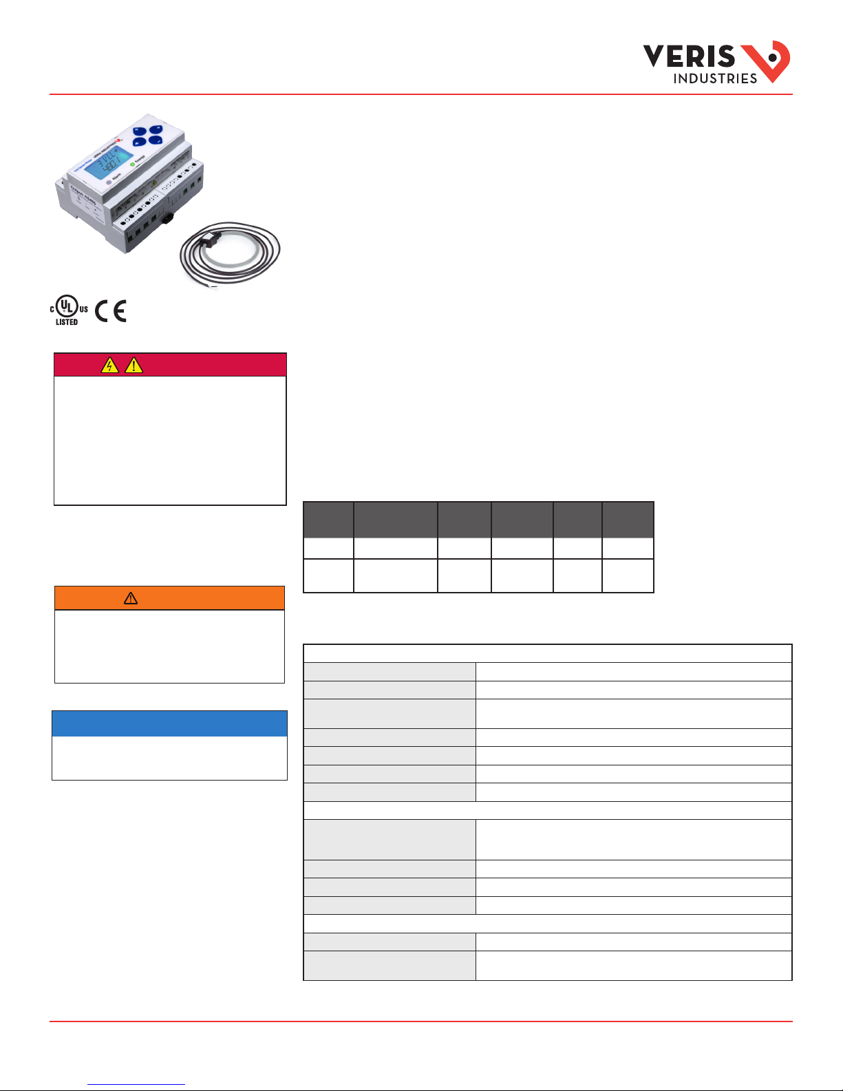
E683 Series CT
(sold separately)
TM
E50H2A, E50H5A
Compact Power and Energy Meters
With BACnet MS/TP Support
For Use Only With E683 Series Rope CTs
Product Overview
The E50H2A and E50H5A DIN rail power meters provide a solution for measuring energy data with a single device.
Inputs include control power, CT, and 3-phase voltage. Both models support BACnet MS/TP protocol. The E50H2A
has one pulse contact input and a phase loss alarm output. The E50H5A has data logging capability and two pulse
contact inputs. The LCD screen on the faceplate allows instant output viewing. These meters include built-in CT
integrators and CT power supplies. The E50H2A and E50H5A work only with Veris E683 series rope style CTs.
The meter is housed in a plastic enclosure suitable for installation on T35 DIN rail according to EN50022. It can be
mounted with any orientation over the entire ambient temperature range, either on a DIN rail or in a panel. The
meters are not sensitive to CT orientation, reducing installation errors.
Product Identication
Model
E50H2A
E50H5A
BACnet MS/TP
Protocol Output
• • • •
• • •
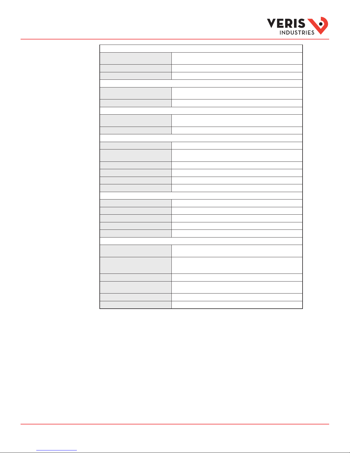
Specications
1
Real Power a nd Energy IEC 62053-22 Class 0.5S, ANSI C12.20 0.5%
React ive Power and Energ y IEC 62053-23 Class 2, 2%
Data Update Rate 1 se c
Type of Measurement True RMS up to the 21st harmonic 60 Hz; One to thre e phase AC system
Measured AC Voltage Minimum 90 V
Metering Over-Range +20%
Frequency Range 45 to 65 Hz
Measurement Input Range E683 Series rope sty le CTs only (CTs must be rated for connection to Class 1
Alarm
Output
Full Data
Set
Data
Logging
Pulse
Input
•
(2 pulses)
MEASUREMENT ACCURACY
Curren t 0.4% (+0.015% per °C deviation from 25 °C) from 5% to 100% of range;
Voltage 0.4% (+0.015% per °C deviation f rom 25 °C) from 90 V
Sample Rate 2520 samples per second
Impedance 2.5 MΩ
CT Scaling 50 to 5000 A measured range*; 400 to 5000 A breaker size
0.8% (+0.015% per °C deviation from 25 °C) fro m 1% to 5% of range
to 600 Vac
L-N
INPU T VOLTAGE CH ARACTER ISTICS
(156 V
) for stated accuracy;
L-N
L-L
(347 V
UL Maximum: 600 V
CE Maximum: 300 V
/5 MΩ
L-N
L-L
INPU T CURREN T CHARACTE RISTICS
voltage inputs)
);
L-L
L-N
L-N
L-L
ZL0117- 0H Page 1 of 28 ©2017 Veris Industries USA 800.354.8556 or +1.503.598.4564 / support@veris.com 0517
Alta Labs, E nercept, Ensp ector, Hawkeye, Trus tat, Aerospo nd, Veris, and th e Veris ‘V’ log o are tradema rks or regist ered tradem arks of Veris Ind ustries, L. L.C. in the USA and /or other count ries.
Other companies’ trademarks are hereby acknowledged to belong to their respective owners.
Installation Guide
Power Monitoring
Specications
(cont.)
CONTR OL POWER
AC 5 VA max .; 90 V min.
UL Maximum: 600 V
DC** 3W max.; UL and CE: 125 to 300 Vdc
Ride Through Time 100 msec at 120 Vac
Pulse Solid-st ate or mechanical contacts (current less than 1 mA);
E50H2A: 1 pulse input; E50H5A: 2 pulse inputs
Minimum Pulse Width 20 msec
Alarm Contacts (E50H2A only) N.C., static output; (30 Vac/dc, 100 mA max.@ 25 °C, derate 0. 56 mA per °C
RS- 485 Port 2-wire, 9600 to 115.2 kbaud, BACnet MS/ TP
Weight 0.62 lb (0. 28 kg)
IP Degree of Protection
(IEC 60 529)
Display Characteristics Back-lit blue LCD
Terminal Block Screw Torque 0.37 to 0.44 f t-lb (0.5 to 0.6 N·m)
Terminal Block Wire Size 24 to 14 AWG (0.13 to 2.08 mm
Operating Temperature Range -30 to 70 °C (22 to 158 °F)
Storage Temperature Range - 40 to 85 °C (-40 to 185 °F)
Humidity Range <95% RH non-condensing
Altitude of Operation 3000 m
Mounting Location Not suitable for wet locations. Indoor use only.
US and Canada CAT III, Pollution Degree 2;
Europe (CE) IEC 61010-1
Dielectric Withstand Per UL 508, IEC 61010-1
Conducted and Radiated Emissions FCC part 15 Class B, EN 55011/EN 61000 Class B (resid ential and light
Conducted and Radiated Immunity EN 61000 Class A (heav y industrial)
US and Cana da (cULus) UL 508 (op en type device)/CSA 22. 2 No. 14-05
*Not recommended for environments where high harmonic content is present.
** External DC current limiting is required, see fuse recommendations.
above 25 °C)
MECHANICAL CHARACTERISTICS
IP40 front disp lay; IP20 meter
Rail T35 (35mm) DIN Rail per EN 50022
OPERATING CONDITIONS
COMPLIANCE INFORMATION
for distribution systems up to 347 V
CAT III, Pollution Degree 2;
for distribution systems up to 300 V
industrial)
INPUT
OUTPUT
L-L
(347 V
L-N
); CE Maximum: 30 0 V
2
)
/600Va c
L-N
L-N
L-L
L-N
TM
ZL0117- 0H Page 2 of 28 ©2017 Veris Industries USA 800.354.8556 or +1.503.598.4564 / support@veris.com 0517
Alta Labs, E nercept, Ensp ector, Hawkeye, Trus tat, Aerospo nd, Veris, and th e Veris ‘V’ log o are tradema rks or regist ered tradem arks of Veris Ind ustries, L. L.C. in the USA and /or other count ries.
Other companies’ trademarks are hereby acknowledged to belong to their respective owners.

Installation Guide
Power Monitoring
Table of Contents
TM
Dimensions 4
Data Outputs 4
Product Diagram 5
Display Screen Diagram 5
Installation 6
Supported System Types 7
Wiring Symbols 7
Wiring 8
Control Power Diagrams 9
Quick Setup Instructions 10
Pulse Contact Input 11
User Interface Menu Abbreviations Dened 11
User Interface for Data Conguration 12
Alert/Reset Information 13
User Interface for Setup 14
RS-485 Communications 16
BACnet Default Settings 17
BACnet Programming Information 18
Troubleshooting 28
China RoHS Compliance Information (EFUP Table) 28
ZL0117- 0H Page 3 of 28 ©2017 Veris Industries USA 800.354.8556 or +1.503.598.4564 / support@veris.com 0517
Alta Labs, E nercept, Ensp ector, Hawkeye, Trus tat, Aerospo nd, Veris, and th e Veris ‘V’ log o are tradema rks or regist ered tradem arks of Veris Ind ustries, L. L.C. in the USA and /or other count ries.
Other companies’ trademarks are hereby acknowledged to belong to their respective owners.
Installation Guide
Power Monitoring
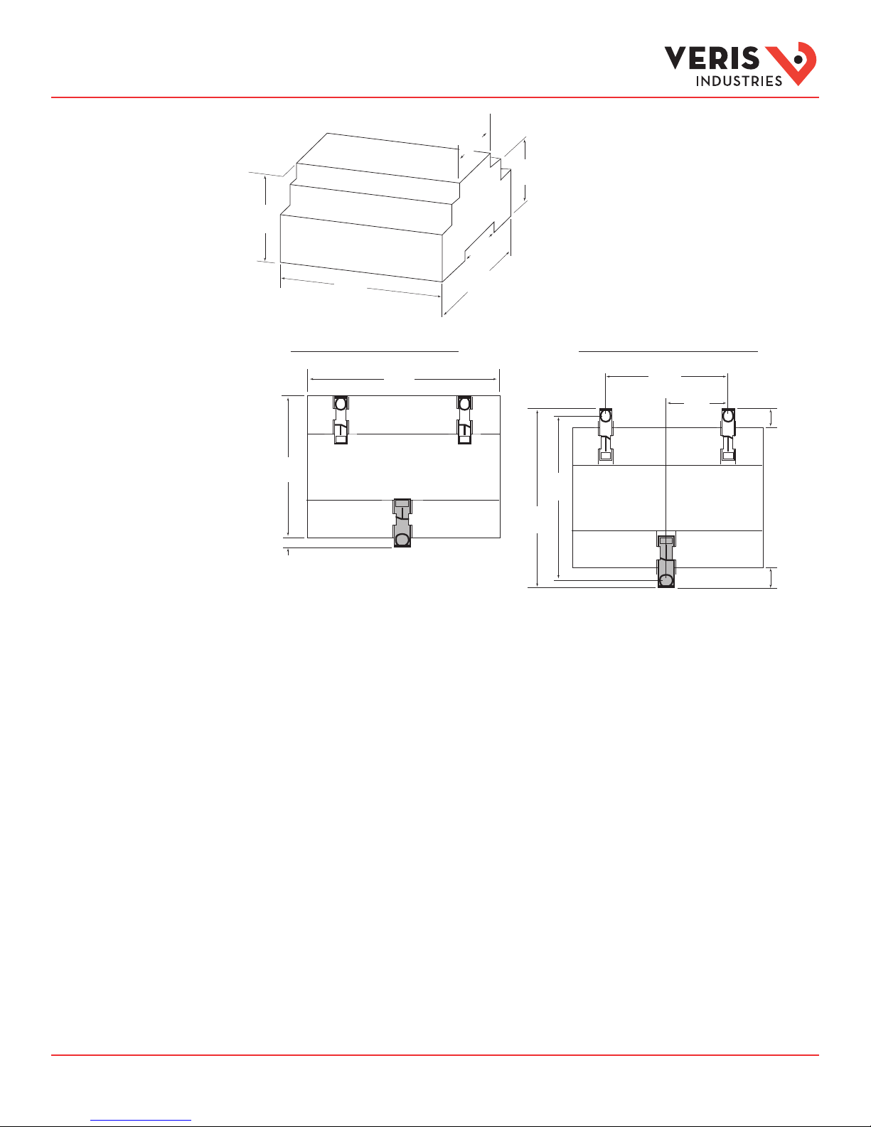
Dimensions
1.8”
(45mm)
1.9”
(48mm)
2.3”
(59mm)
1.5”
(39mm)
4.2”
(107mm)
3.6”
(91mm)
Bottom View (DIN Mount Option) Bottom View (Screw Mount Option)
2.4 “
(61 mm)
+
0.2 “
(4 mm)
3.6 “
(91 mm)
4.2 “
(107 mm)
3.9“
(99 mm)
4.3 “
(109 mm)
1.2 “
(31 mm)
TM
++
0.3 “
(8 mm)
0.4 “
(10 mm)
Data Outputs
Full Data Set (FDS):
Power (kW)
Energy (kWh)
Congurable for CT & PT ratios, system type, and passwords
Diagnostic alerts
Current: 3-phase average
Volts: 3-phase average
Current: by phase
Volts: by phase Line-Line and Line-Neutral
Power: Real, Reactive, and Apparent 3-phase total and per phase
Power Factor: 3-phase average and per phase
Frequency
Power Demand: Most Recent and Peak
Demand Conguration: Fixed, Rolling Block, and External Sync
Real Time Clock: uses BACnet Time Synchronization services
Data Logging (E50H5A only; includes all FDS outputs, plus):
3 BACnet Log_Events: each buer holds 5760 time-stamped 32-bit entries
(User congures which 3 data points are stored in these buers)
User congurable logging interval
(When congured for a 15 minute interval, each buer holds 60 days of data)
Continuous and Single Shot logging modes: user selectable
ZL0117- 0H Page 4 of 28 ©2017 Veris Industries USA 800.354.8556 or +1.503.598.4564 / support@veris.com 0517
Alta Labs, E nercept, Ensp ector, Hawkeye, Trus tat, Aerospo nd, Veris, and th e Veris ‘V’ log o are tradema rks or regist ered tradem arks of Veris Ind ustries, L. L.C. in the USA and /or other count ries.
Other companies’ trademarks are hereby acknowledged to belong to their respective owners.
Installation Guide
Neutral
Control
Power
kWh
1234.5
kWh
1234.5
Neutral
Control
Power
Power Monitoring
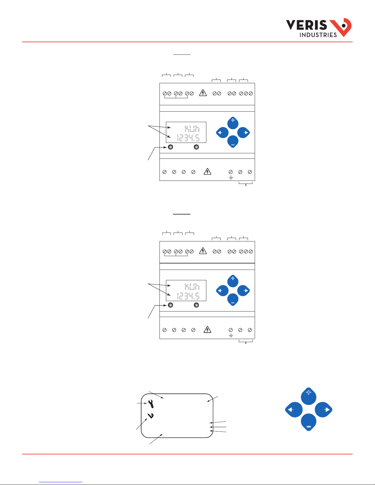
Product Diagrams
Two 5-character rows
of display text.
Top row alphanumeric;
Bottom row numeric only
The red Alarm LED lights
when any of the 3 phase
voltages drop below the
selected threshold.
The green Energy LED is not
used on the E5xH2A.
E50H2A
IA
IB
X2 X1 X2 X1 X2 X1
(X2) A (X1) (X2) B (X1) (X2) C (X1)
CT Inputs
E683 Series Only
IC
Phase Loss
Alarm Output
Pulse Input
RS-485
+ - S
+
Alarm Energy
VOLTAGE INPUTS
CAT III 50/60 Hz
A B C N 1 2
VA
UL: 90V
- 600V
CE: 90V
L-N
L-L
VB
VC
–
CONTROL POWER
- 300V
L-N
L-N
0.1A 50/60 Hz
Earth
E50H5A
TM
BACnet
Shield
Display Screen
Diagram
IA
IB
Two 5-character rows
of display text.
X2 X1 X2 X1 X2 X1
(X2) A (X1) (X2) B (X1) (X2) C (X1)
CT Inputs
E683 Series Only
IC
Pulse Input 1
Pulse Input 2
BACnet
Pulse Inputs
1 2 + - S
RS-485
+
Shield
Top row alphanumeric;
Bottom row numeric only
Alarm Energy
–
The red Alarm LED lights
when any of the 3 phase
voltages drop below the
VOLTAGE INPUTS
CAT III 50/60 Hz
UL: 90V
- 600V
CE: 90V
L-N
L-L
L-N
- 300V
L-N
CONTROL POWER
0.1A 50/60 Hz
selected threshold.
The green Energy LED lights
when the pulse 1 input
contacts are active or closed.
A B C N 1 2
VA
VB
VC
Earth
LCD Screen: Buttons:
Screen Name or Units
Diagnostic Alert:
indicates that one or
more of the alarm
bits (Binary_Objects
1-15) are active.
Logo
Numeric Data
♥
Tx
Rx
ERR
Alive Indicator
RS-485 Equipped Units Only:
Transmit Data
Receive Data
Receive Data Error
(Left)
Back
(Up)
Select
+
(Right)
Next
–
(Down)
Select
ZL0117- 0H Page 5 of 28 ©2017 Veris Industries USA 800.354.8556 or +1.503.598.4564 / support@veris.com 0517
Alta Labs, E nercept, Ensp ector, Hawkeye, Trus tat, Aerospo nd, Veris, and th e Veris ‘V’ log o are tradema rks or regist ered tradem arks of Veris Ind ustries, L. L.C. in the USA and /or other count ries.
Other companies’ trademarks are hereby acknowledged to belong to their respective owners.
Installation Guide
Power Monitoring
Installation
TM
Disconnect power prior to installation.
Reinstall any covers that are displaced during the installation before powering the unit.
Mount the meter in an appropriate electrical enclosure near equipment to be monitored.
Do not install on the load side of a Variable Frequency Drive (VFD), aka Variable Speed Drive (VSD)
or Adjustable Frequency Drive (AFD).
The meter can be mounted in two ways: on standard 35 mm DIN rail or screw-mounted to the interior surface of the enclosure.
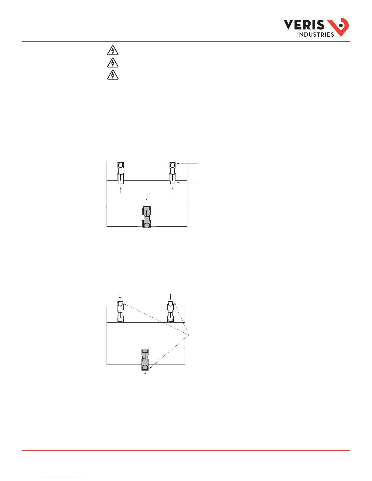
A. DIN Rail Mounting
1. Attach the mounting clips to the underside of the housing by sliding them into the slots from the inside. The stopping pegs
must face the housing, and the outside edge of the clip must be ush with the outside edge of the housing.
2. Snap the clips onto the DIN rail. See the diagram of the underside of the housing (below).
Clip flush with
outside edge
Snap onto
Insert clips from inside
DIN rail
3. To reduce horizontal shifting across the DIN rail, use two Veris AV02 end stop clips.
B. Screw Mounting
1. Attach the mounting clips to the underside of the housing by sliding them into the slots from the outside. The stopping pegs
must face the housing, and the screw hole must be exposed on the outside of the housing.
2. Use three #8 screws (not supplied) to mount the meter to the inside of the enclosure. See the diagram of the underside of the
housing (below).
Insert clips from outside
Screw holes
exposed for
mounting
ZL0117- 0H Page 6 of 28 ©2017 Veris Industries USA 800.354.8556 or +1.503.598.4564 / support@veris.com 0517
Alta Labs, E nercept, Ensp ector, Hawkeye, Trus tat, Aerospo nd, Veris, and th e Veris ‘V’ log o are tradema rks or regist ered tradem arks of Veris Ind ustries, L. L.C. in the USA and /or other count ries.
Other companies’ trademarks are hereby acknowledged to belong to their respective owners.
Installation Guide
Power Monitoring
Supported System
Types
Number
of wires
Single-Phase Wiring
2 1 A 2 A, N L-N 10 1L + 1n AN 1
2 1 A 2 A, B L-L 11 2L AB 2
3 2 A, B 3 A, B, N L-L with N 12 2L + 1n AB AN, BN AN-BN 3
Three-Phase Wiring
3 3 A, B, C 3 A, B, C Delta 31 3L AB, BC, CA AB-BC-CA 4
4 3 A, B, C 4 A, B, C, N Grounded
Qty ID Qty ID Type BACnet object
TM
The E50HxA power meters have a number of dierent possible system wiring congurations (see Wiring section). To congure the
meter, set the System Type via the User Interface or by writing the Present_Value of AV2 with the System Type value in the table
below. The System Type tells the meter which of its current and voltage inputs are valid, which are to be ignored, and if neutral
is connected. Setting the correct System Type prevents unwanted energy accumulation on unused inputs, selects the formula
to calculate the Theoretical Maximum System Power, and determines which phase loss algorithm is to be used. The phase loss
algorithm is congured as a percent of the Line-to-Line System Voltage (except when in System Type 10) and also calculates the
expected Line to Neutral voltages for system types that have Neutral (12 & 40).
Values that are not valid in a particular System Type display as “----” on the User Interface or as QNAN in the BACnet objects.
CTs Voltage Connections System Type Phase Loss Measurements Wiring
Diagram
Wye
AV2
40 3L + 1n AB, BC, CA AN, BN, CN AN-BN-CN &
User Interface:
SETUP>S SYS
VLL VLN Balance Diagram
number
5, 6
AB-BC-CA
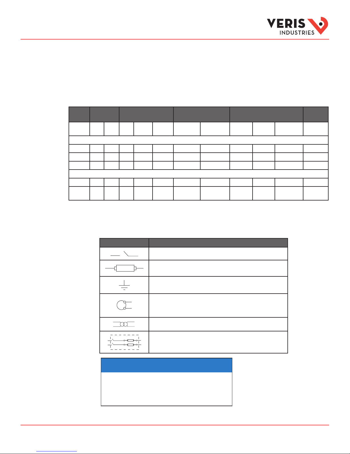
Wiring Symbols
To avoid distortion, use parallel wires for control power and voltage inputs.
The following symbols are used in the wiring diagrams on the following pages.
Symbol Description
Voltage Disconnect Switch
Fuse (installer is responsible for ensuring compliance with local requirements. No
fuses are included with the meter.)
Earth ground
X1
X2
Current Transducer
Potential Transformer
Protection containing a voltage disconnect switch with a fuse or disconnect circuit
breaker. The protection device must be rated for the available short-circuit current at
the connection point.
NOTICE
• This product is designed only for use with E683 Series c urrent transducers (CTs).
• DO NOT USE CURRENT OUTPUT (e.g. 5A) CTs ON THIS PRODUCT.
Failure to follow these instructions can result in equipment damage.
RISK OF EQUIPMENT DAMAGE
ZL0117- 0H Page 7 of 28 ©2017 Veris Industries USA 800.354.8556 or +1.503.598.4564 / support@veris.com 0517
Alta Labs, E nercept, Ensp ector, Hawkeye, Trus tat, Aerospo nd, Veris, and th e Veris ‘V’ log o are tradema rks or regist ered tradem arks of Veris Ind ustries, L. L.C. in the USA and /or other count ries.
Other companies’ trademarks are hereby acknowledged to belong to their respective owners.
Installation Guide
Power Monitoring
Wiring
TM
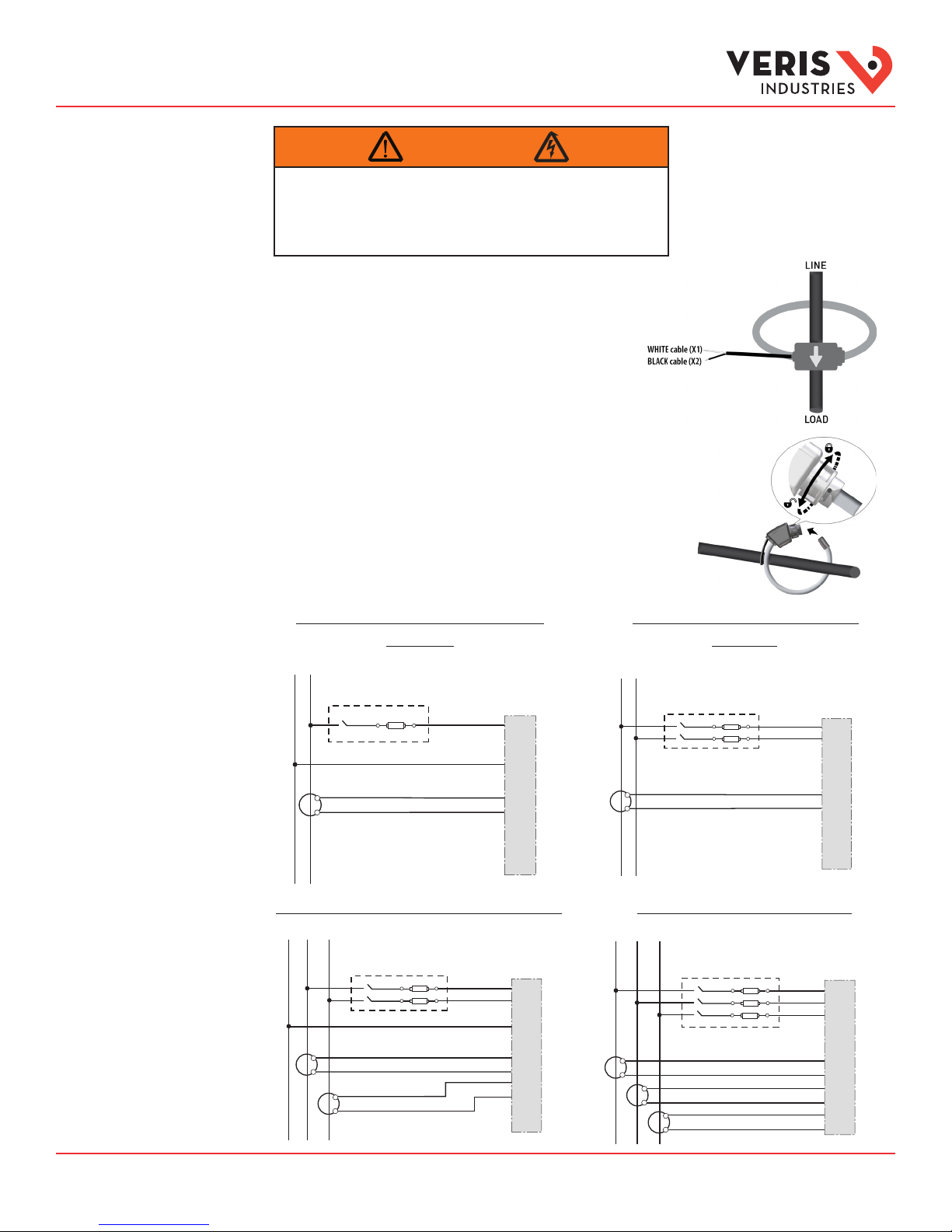
WARNING
RISK OF ELECTRIC SHOCK OR PERMANENT EQUIPMENT DAMAGE
CT terminals are referenced to the meter’s neutral and may be at elevated voltages:
· Do not contact meter terminals while the unit is connected
· Do not connect or short other circuits to the CT terminals
Failure to follow these instructions may cause injury, death or equipment damage.
1. Turn o all power supplying this device and the equipment in which it is
installed before working on the device or equipment.
2. Always use a proerly rated voltage sensing device to conrm that all power
is o.
3. Connect the CT output leads to the meter inputs. The white wire is the X1
lead. The E683x CT has an arrow indicating the source side.
4. Release the clasp on one side of the CT and open it on the hinge.
5. Fit the Rogowski coil around the conductor, bringing the coil ends
together.
6. Lock the coil by turning the ring clockwise as shown in the diagram
at right.
7. Reconnect power to the panel.
Diagram 1: 1-Phase Line-to-Neutral 2- Wire
System 1 CT
N L1
Use System Type 10 (1L + 1n)
X1
X2
A
B
C
N
White
Black
X1
A
X2
X1
B
X2
X1
C
X2
Diagram 3: 1-Phase Direct Voltage Connection 2 CT
N
L1 L2
X1
X2
Use System Type 12 (2L + 1n) Use System Type 31 (3L)
A
B
C
N
White
Black
X1
X2
White
Black
X1
A
X2
X1
B
X2
X1
C
X2
Diagram 2: 1-Phase Line-to-Line 2-Wire
System 1 CT
L1 L2
X1
X2
Use System Type 11 (2L)
White
Black
Diagram 4: 3-Phase 3-Wire 3 CT no PT
L1 L2 L3
X1
X1
X2
X2
White
Black
White
X1
X2
Black
White
Black
A
B
C
N
X1
A
X2
X1
B
X2
X1
C
X2
A
B
C
N
X1
A
X2
X1
B
X2
X1
C
X2
ZL0117- 0H Page 8 of 28 ©2017 Veris Industries USA 800.354.8556 or +1.503.598.4564 / support@veris.com 0517
Alta Labs, E nercept, Ensp ector, Hawkeye, Trus tat, Aerospo nd, Veris, and th e Veris ‘V’ log o are tradema rks or regist ered tradem arks of Veris Ind ustries, L. L.C. in the USA and /or other count ries.
Other companies’ trademarks are hereby acknowledged to belong to their respective owners.
Installation Guide
Power Monitoring
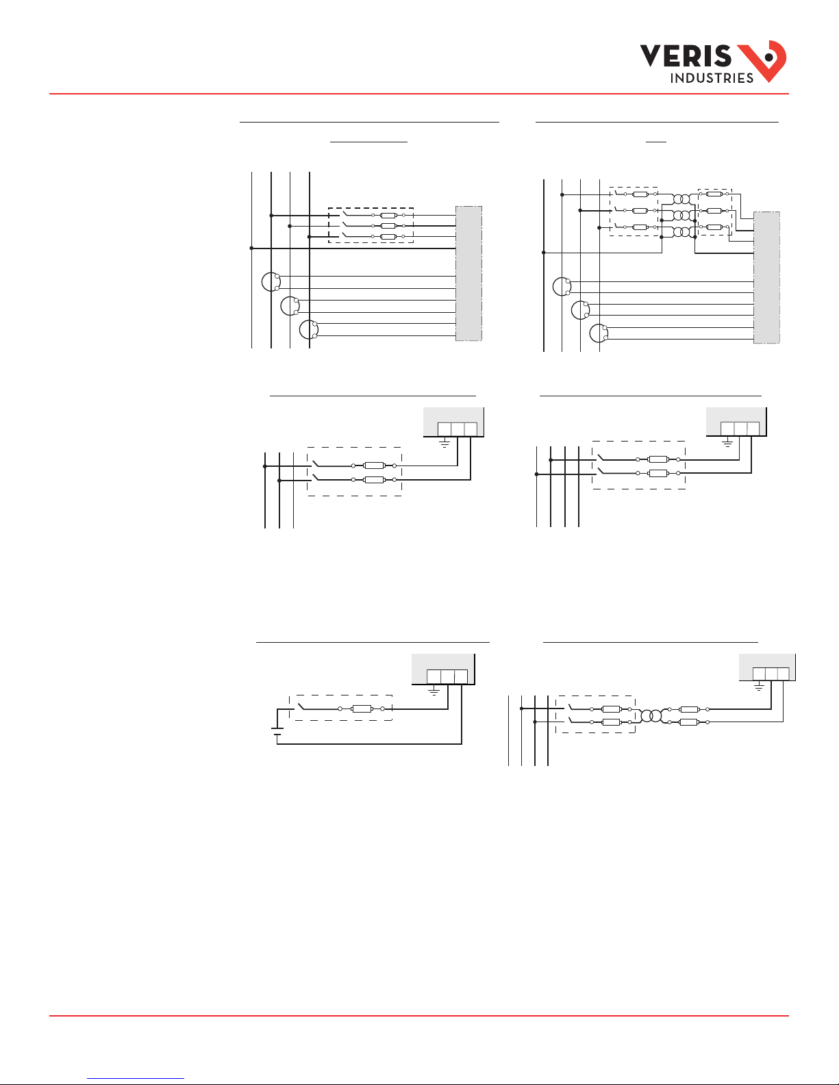
Wiring (cont.)
Control Power
Diagram 5: 3-Phase 4-Wire Wye Direct Voltage Input
Connection 3 CT
Use System Type 40 (3L + 1n)
L1N L2 L3
A
B
C
N
X1
X2
X1
X2
X1
X2
White
Black
White
Black
White
Black
X1
A
X2
X1
B
X2
X1
C
X2
Direct Connect Control Power (Line to Line)
L1
L2 L3
1 2G
Diagram 6: 3-Phase 4-Wire Wye Connection 3 CT
3 PT
Use System Type 40 (3L + 1n)
L1N L2 L3
A
B
C
N
X1
X1
X2
X2
X1
X2
White
Black
White
Black
White
Black
X1
X2
X1
X2
X1
X2
Direct Connect Control Power (Line to Neutral)
L1N L2 L3
1 2G
TM
A
B
C
Line to Line from 90 VAC to 600 VAC (UL). In UL installations the
Line to Neutral from 90 VAC to 347 VAC (UL) or 300 VAC (CE)
lines may be oating (such as a delta). If any lines are tied to an
earth (such as a corner grounded del ta), see the Line to Neutral
installation limits. In CE compliant installations, the lines must
be neutral (earth) referenced at less than 300 VAC
Direct Connect Control Power (DC Control Power)
L-N
Control Power Transformer (CPT) Connection
1 2G
L1N L2 L3
DC Control Power from 125 VDC to 300 VDC
(UL and CE max.)
The Control Power Transformer may be wired L-N or L-L. Output to
meet meter input requirements
Fuse Recommendations
Keep the fuses close to the power source (obey local and national code requirements).
For selecting fuses and circuit breakers, use the following criteria:
• Select current interrupt capacity based on the installation category and fault current capability.
• Select over-current protection with a time delay.
• Select a voltage rating sucient for the input voltage applied.
• Provide overcurrent protection and disconnecting means to protect the wiring. For AC installations, use Veris AH02,
AH03, AH04, or equivalent. For DC installations, provide external circuit protection. Suggested: 0.5 A, time delay fuses.
• The ear th connection (G) is required for electromagnetic compatibility (EMC) and is not a protective earth ground.
1 2G
ZL0117- 0H Page 9 of 28 ©2017 Veris Industries USA 800.354.8556 or +1.503.598.4564 / support@veris.com 0517
Alta Labs, E nercept, Ensp ector, Hawkeye, Trus tat, Aerospo nd, Veris, and th e Veris ‘V’ log o are tradema rks or regist ered tradem arks of Veris Ind ustries, L. L.C. in the USA and /or other count ries.
Other companies’ trademarks are hereby acknowledged to belong to their respective owners.
 Loading...