

VERIS INDUSTRIES, INC. E31E Series Installation Manual
Installation Guide
the user will be required to correct the interference at his own expense.
Power Monitoring
DANGER
HAZARD OF ELECTRIC SHOCK, EXPLOSION, OR ARC FLASH
• Follow safe electrical work practices. See NFPA 70E in the USA, or applicable local codes.
• This equipment must only be installed and serviced by qualified electric al personnel.
• Read, understand and follow the instructions before installing this product.
• Turn off all power supplying equipment before working on or inside the equipment.
• Product may use multiple voltage/power sources. Be sure all sources of power
have been disconnected before servicing.
• Use a properly rated voltage sensing device to confirm power is off.
DO NOT DEPEND ON THIS PRODUCT FOR VOLTAGE INDICATION
• Only install this product on insulated conductors.
Failure to follow these instructions will result in death or serious injury.
A qualied person is one who has skills and knowledge related to the construction and
operation of this electrical equipment and the installation, and has received safety
training to recognize and avoid the hazards involved. NEC2011 Article 100
No responsibility is assumed by Veris Industries for any consequences arising out of the
use of this material.
NOTICE
• This product is not intended for life or safety applications.
• Do not install this product in hazardous or classified locations.
• The installer is responsible for conformance to all applicable codes.
• Mount this product inside a suitable fire and electrical enclosure.
FCC PART 15 INFORMATION
NOTE: This equipment has been tested by the manufacturer and found
to comply with the limits for a class A digital device, pursuant to part
15 of the FCC Rules. These limits are designed to provide reasonable
protection against harmful interference when the equipment is
operated in a commercial environment. This equipment generates,
uses, and can radiate radio frequency energy and, if not installed and
used in accordance with the instruction manual, may cause harmful
interference to radio communications. Operation of this equipment in
a residential area is likely to cause harmful interference in which case
Modifications to this product without the express authorization of
Veris Industries nullify this statement.
This Cla ss A digital a pparatu s complies w ith Canadi an ICES- 003.)
TM
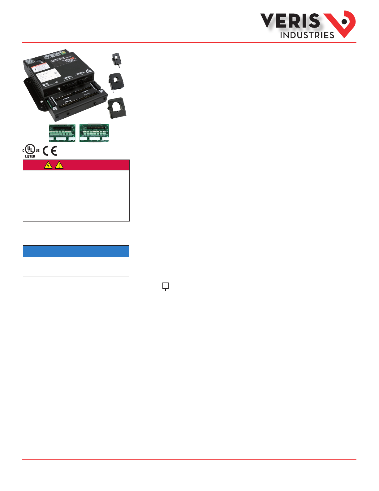
E31E Series
Split-Core Panelboard Monitoring System
Product Overview
The E31E Series panelboard monitoring system is designed to measure the current, voltage, and energy
consumption of up to 92 circuits (84 branch circuits, 2 3-phase mains, 2 neutrals), enabling users to monitor
two panelboards or an entire data center PDU with a single product. It increases the board’s current monitoring
capability by combining the functions of two boards into one device.
The E31E consists of a data acquisition module, up to four current sensor adapter boards, and up to 84 split-core
branch current sensors (50A, 100A, or 200A), with eight auxiliary inputs. Each conductor passes through the
appropriate branch current sensor before terminating at the breaker. Each sensor transmits the current data to the
data acquisition board. The E31E measures both current and power for the mains and branch circuits. The E31E can
easily accommodate dierent panel congurations, including any combination of multi-phase breaker positions,
voltage phase mapping, and breaker sizes. To congure the E31E for operation, download the E3x Conguration
Tool and the E3x Commissioning Guide from www.veris.com.
Data is transmitted via ethernet with Modbus TCP, BACnet IP or SNMP protocol, or via RS-485 with Modbus RTU or
BACnet MS/TP protocols. Some protocols can be used simultaneously, and the ethernet protocols all support access
by multiple masters. Each data acquisition board requires two Modbus addresses, one for each set of 42 current
sensors, and four auxiliary inputs. Data is updated roughly every two seconds. When a circuit exceeds the userdened thresholds, the E31E activates the alarm indicators. The communication interfaces and protocols require
some conguration at the time of installation.
Product Identification
# of CTs
E31E
002 = 2 adapter boards, no CTs, no cables
004 = 4 adapter boards, no CTs, no cables
42 = 2 adapter boards, 42 50A CTs, 2 4 ft. round ribbon cables
84 = 4 adapter boards, 84 50A CTs, 4 4 ft. round ribbon cables
Z206855-0B Page 1 of 26 ©2014 Veris Industries USA 800.354.8556 or +1.503.598.4564 / support@veris.com 04142
Alta Labs, E nercept, Ensp ector, Hawkeye, Trus tat, Aerospo nd, Veris, and th e Veris ‘V’ log o are tradema rks or registe red tradema rks of Veris Ind ustries, L. L.C. in the USA and /or other countri es.
Find Quality Products Online at: sales@GlobalTestSupply.com
Other companies’ trademarks are hereby acknowledged to belong to their respective owners.
www.GlobalTestSupply.com

Installation Guide
Power Monitoring
EESeries
TM
Specifications
Input Power
Terminal Block Torque
Wire Size
Terminal Block Torque
Wire Size
Power/Energy
Voltag e
Current
Minimum ON Current
Sampling Frequency
Update Rate
Physical Interface
Protocols Supported
Physical Interface
Serial Protocols Supported
Address Range
Baud Rate
Parity
Communication Format
Termination
Terminal Block Torque
Wire Size
Ribbon Cable Support
Operating Temperature Range
Storage Temperature Range
Altitude of Operation
Approvals
INP UTS
100-277VAC, 50 /6 0 Hz, 15VA max.
4.4 to 5. 3 in-lb (0. 5 to 0.6 N-m)
up to 12 AWG
AUXI LIARY I NPU TS
3.5 to 4.4 in-lb (0.4 to 0.5 N- m)
up to 14 AWG
ACCUR ACY
IEC 620 53 -21 Class 1, AN SI C12.1-2008
(1% System accuracy includes both the E31E main unit and 50A or 100A
branch current sensors)
±0.5% of reading 90 -277VAC line-to-neutral
±0.5% of reading
50 mA
OP E RAT I ON
2560 Hz
Modbus: ~1.8 seconds (both panels )
BACnet: 14 seconds
SNMP: 20 seconds
ETHERNET COMMUNICATION
RJ45 connector with 10/100 Mbit Ethernet
Modbus TCP, BACnet IP, SNMP V2c
SERIAL C OMMUN ICATION
2-wire RS- 485
Modbus RTU or BACnet MSTP
Fixed at address 1 & 2 for Modbus RTU, 0 -127 for BACnet MS / TP
9600, 19200, 38400
Modbus RTU: N ONE, ODD, EVEN
BACnet MS/ TP: NO NE (fixed)
8-data-bits, 1-start-bit, 1-stop- bit
2x3 position connector
4.4 to 5. 3 in-lb (0. 5 to 0.6 N-m)
up to 16 AWG
MECHAN ICAL
4 ft. (1.2 m ) flat ribbon cable ships standard with 42 and 8 4 current
sensor models;
up to 20 ft. ( 6 m) available
OPERATING CO NDITION S
0° to 60 °C ( 32° to 140 °F) (<95% RH noncondensing)
-4 0° to 70° C (- 40 ° to 158°F)
300 0 m max.
COMPLIANCE INFORMATION
UL5 08 , EN 61010 -1
Z206855-0B Page 2 of 26 ©2014 Veris Industries USA 800.354.8556 or +1.503.598.4564 / support@veris.com 04142
Alta Labs, E nercept, Ensp ector, Hawkeye, Trus tat, Aerospo nd, Veris, and th e Veris ‘V’ log o are tradema rks or registe red tradema rks of Veris Ind ustries, L. L.C. in the USA and /or other countri es.
Find Quality Products Online at: sales@GlobalTestSupply.com
Other companies’ trademarks are hereby acknowledged to belong to their respective owners.
www.GlobalTestSupply.com
Installation Guide
Power Monitoring
EESeries
TM
Table of Contents
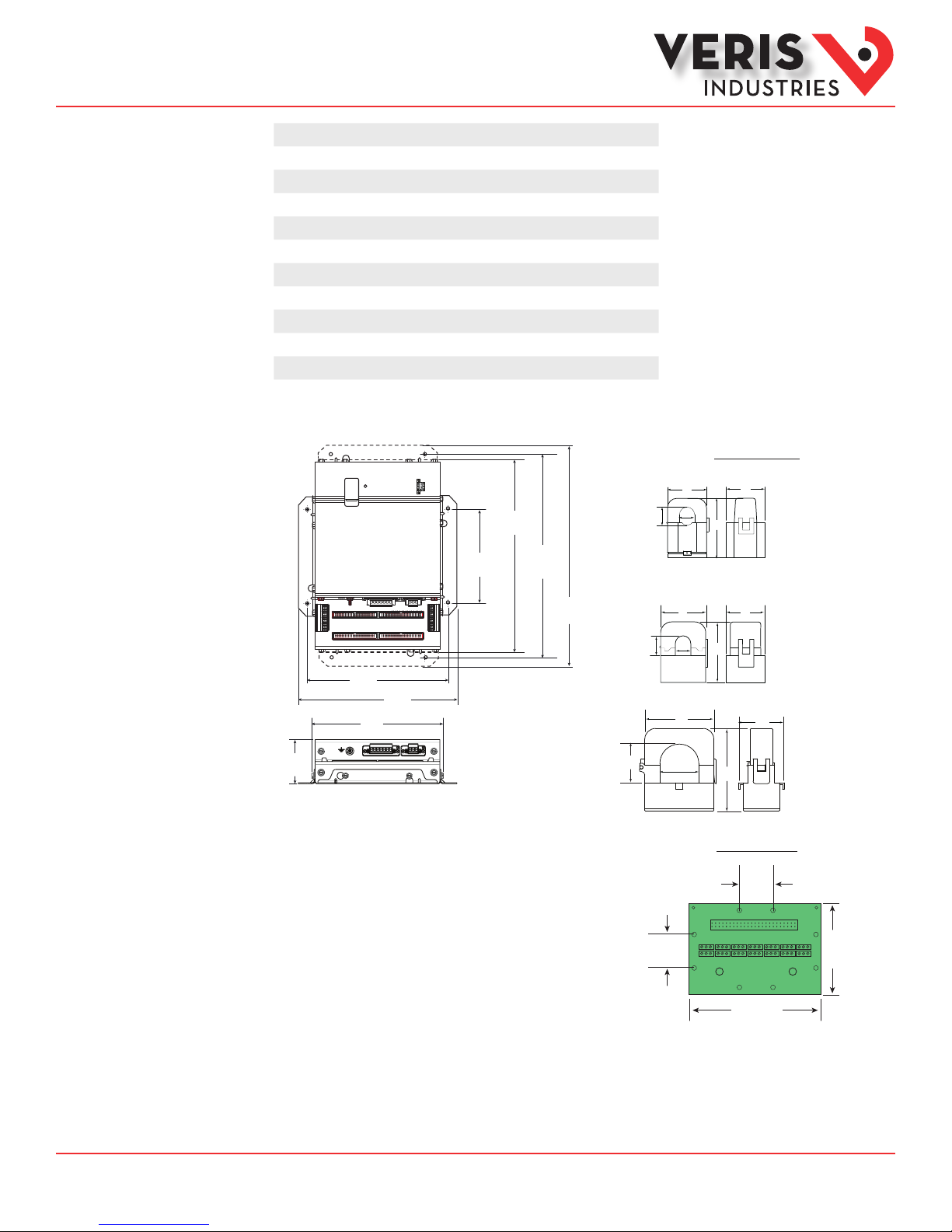
Dimensions
Dimensions 3
Product Diagram 4
Data Outputs 5
Split-Core Current Sensors 7
Installation 7
Wiring 11
Gateway Conguration 13
BACnet PICS 23
General BACnet Programming Information 24
General SNMP Programming Information 25
Troubleshooting 26
China RoHS Compliance Information (EFUP Table) 26
12.1”
(307 mm)
2x: 5.9”
(150 mm)
12.8”
(325 mm)
Current Sensors
D
C
B
A
E
E31CT0 50 Amp
A = 1.0” (26 mm)
B = 0.5” (11 mm)
C = 0.4” (10 mm)
D = 0.9” (23 mm)
E = 1.6” (40 mm)
8.9”
(225 mm)
2.8”
(71 mm)
Note: The dotted li nes indicate dimensions if the t wo brackets are placed
for horizontal m ounting. At the factory, the bracket s are placed for
vertical mounting. See Installation section for more information.
8.2”
(210 mm)
10.0”
(253 mm)
13.9”
(353 mm)
D
C
B
A
E
E31CT1 100 Amp
A = 1.5” (39 mm)
B = 0.8” (20 mm)
C = 0.7” (16 mm)
D = 1.6” (40 mm)
E = 2.1” (53 mm)
D
A
E31CT3 200 Amp
A = 1.5” (39 mm)
B
C
E
B = 1.25” (32 mm)
C = 1.25” (32 mm)
D = 2.5” (64 mm)
E = 2.8” (71 mm)
Adapter Board
1.00”
(26 mm)
1.00”
(26 mm)
4.6”
(117 mm)
2.75”
(70 mm)
Z206855-0B Page 3 of 26 ©2014 Veris Industries USA 800.354.8556 or +1.503.598.4564 / support@veris.com 04142
Alta Labs, E nercept, Ensp ector, Hawkeye, Trus tat, Aerospo nd, Veris, and th e Veris ‘V’ log o are tradema rks or registe red tradema rks of Veris Ind ustries, L. L.C. in the USA and /or other countri es.
Find Quality Products Online at: sales@GlobalTestSupply.com
Other companies’ trademarks are hereby acknowledged to belong to their respective owners.
www.GlobalTestSupply.com
Installation Guide
Power Monitoring
EESeries
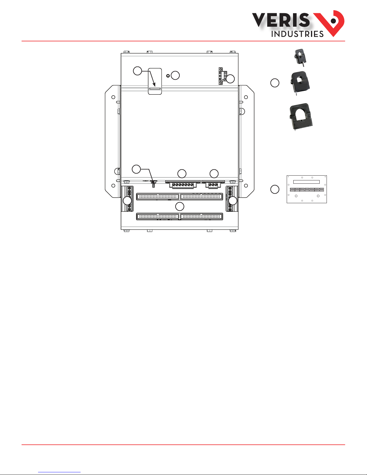
Product Diagram
TM
1
4
7 7
1. Ethernet port: provides ethernet connection for the gateway component
2
8
3
65
9
10
2. Power LED: indicates power is applied to the meter.
3. 2x3 RS-485 Serial Connection
4. Grounding post
5. Voltage Taps: 1, 2, or 3 phase plus neutral connections. For voltage sensing and power calculations
6. Control (Mains) Power Connection: Easy 2-wire 100-277 VAC 50/60 Hz connection.
7. Auxiliary Inputs: These 0.333 VAC inputs are used for monitoring the main breaker or other high amperage source. Inputs on
the left are for panelboard 2; inputs on the right are for panelboard 1.
8. 50-Pin Ribbon Cable Connectors: 4-foot (0.9 m) ribbon cables are provided for easy connec tion of the adapter boards to this
point of the data acquisition board. Other ribbon cable lengths are available (sold separately). The two connectors on the lef t
are for panelboard 2; the two on the right are for panelboard 1.
Connect adapter boards A and B to the correct ribbon cable connectors for each panel. The top connectors are for Board B, and
the bottom conec tors are for Board A.
Note: Ribbon cables are not included with all E31E models (see Ordering Information).
9. Branch Current Sensors: Each split-core current sensor is capable of monitoring conductors rated up to a maximum of 50, 100,
or 200 amps. Up to 84 sensors can be used with the E31E. One of each style is pictured here.
10. Adapter Board: Includes connectors for a ribbon cable and up to 42 current sensors.
Z206855-0B Page 4 of 26 ©2014 Veris Industries USA 800.354.8556 or +1.503.598.4564 / support@veris.com 04142
Alta Labs, E nercept, Ensp ector, Hawkeye, Trus tat, Aerospo nd, Veris, and th e Veris ‘V’ log o are tradema rks or registe red tradema rks of Veris Ind ustries, L. L.C. in the USA and /or other countri es.
Find Quality Products Online at: sales@GlobalTestSupply.com
Other companies’ trademarks are hereby acknowledged to belong to their respective owners.
www.GlobalTestSupply.com

Installation Guide
Power Monitoring
EESeries
TM
Data Outputs
The E31E provides several types of measurements that give a comprehensive view of power consumption for every monitored load
on the panel:
• Real-time measurements: a live and up-to-date view of present power levels and the factors that aect them.
• Demand measurements: averages of values measured over a specied time interval. The time interval (typically 15
minutes) can be set from 10 seconds to more than a day. The demand calculation can be congured to use single
intervals or the sliding average of up to 6 sub-intervals. Demand measurements are useful for tracking or graphing
load levels over time to correlate with total energy consumption.
• Historic maximum measurements: these measurements store the largest value recorded for a specic measurement
since the last time they were cleared. They are useful for identifying peak levels critical to equipment sizing or demand
limits in utility agreements.
• Accumulated energy measurements: ongoing totals of cumulative energy used since the last time the value was
cleared. Energy values provide the informational basis for billing, cost allocation, carbon oset, BTU equivalent
calculations, and other applications of overall energy use.
• Energy snapshots: energy totals that only change when the demand intervals are updated. They are samples of the
free-running energy accumulators at the end of each demand interval, as congured by the user. These provide energy
readings that are easily correlated to the demand values to simplify the tasks of sub-billing and cost allocation.
• Alarms: provide a warning of excessively high or low current on each branch and aux channel. The user can set two
high-level and two low-level thresholds, and a delay time for latching alarms. Alarms are reported as both non-latched
events and latched events. Non-latching alarms are active while the current exceeds the threshold, but go inactive if
the current returns to a level within the specic thresholds. Latching alarms become active when the current exceeds
the threshold for a time period greater than the specied delay and remain active until they are cleared remotely.
Alarm status can be polled via any protocol. Via BACnet, Subscribe_COV can be used to generate alarm notications.
Via SNMP, alarms drive SNMP event notications.
Advanced Features - The E31E supports a number of of advanced features. Some are always active, and others are congured
manually via Modbus register 62017, BACnet object AV164, or SNMP MIB variable “spanels/panel1/p1Conguration/p1Setup/
p1UserDenedSettings” (OID .1.3.6.1 .4.1.40845.1.30.1.1.6.3.4.0). For models with 42 channels or more, these features are
congured independently for each panel.
• Logical Circuit support: The E31E can be congured to map any set of 1, 2 or 3 channels that are adjacent in the panel
to a logical circuit that provides accurate multi-phase measurement totals. Map these logical circuits by writing the
desired logical circuit number into a set of registers/data objects provided for each branch and aux channel (per panel).
The channels assigned to each logical circuit must be adjacent in the panel (usually used for multi-phase breakers), but
there are no limitations on where those adjacent channels are aligned in the panel (any position where a multi-phase
breaker can be installed). This functionality is always active, but a user selection aects the how the data can be
accessed via Modbus. Measurement data via Modbus for logical circuits is presented in two ways, arranged either by
logical circuit number (looks more like a collection of individual meters) or by measurement type (arranged similar to
the single-phase data section of the point map).
• Legacy point map or alternate logical circuit point map: The E31E can be congured to select a preferred version of the
Modbus registers in the address range 4000 to 9999. If enabled (default), the logical circuits by measurement type
is active. Otherwise, the legacy point maps for 2-phase and 3-phase breakers used in older E3x models is active. The
logical circuits functionality can also be accessed via the “Logical Circuits by Circuit” section of the point map (address
range 10000 to 45000), regardless of the state of this selection.
• Phase angle measurements: The E31E measures the phase angle of every voltage and current input and presents these
measurements (in degrees) in additional data registers/objects. These values are used to verify that current inputs are
assigned to the proper voltage phases and to help determine how power factor variations are inuenced by current
phase changes vs. harmonic distortion. Phase angle measurements are instantaneous and always active.
• User CT phase assignment: In the default mode, the E31E assigns each channel to the corresponding phase that most
3-phase panels implement, so that the user does not have worry about it. The user can opt to replace this selfassignment paradigm with a mode that allows explicit specication of the phase assignment for each channel. The
explicit assignments set by the user are stored by the E31E in non-volatile memory.
• Phase angle reference: The E31E measures the phase angle of every current and voltage input. The user can select
whether the phase angles are stated relative to an absolute reference (the phase angle of voltage input V1) or relative
to the voltage phase assigned to that specic current input channel.
Z206855-0B Page 5 of 26 ©2014 Veris Industries USA 800.354.8556 or +1.503.598.4564 / support@veris.com 04142
Alta Labs, E nercept, Ensp ector, Hawkeye, Trus tat, Aerospo nd, Veris, and th e Veris ‘V’ log o are tradema rks or registe red tradema rks of Veris Ind ustries, L. L.C. in the USA and /or other countri es.
Find Quality Products Online at: sales@GlobalTestSupply.com
Other companies’ trademarks are hereby acknowledged to belong to their respective owners.
www.GlobalTestSupply.com

Installation Guide
Power Monitoring
EESeries
TM
Data Outputs (cont.)
• Signed power: Users can congure the E31E to report power as a signed value indicating whether the power is
currently being delivered (imported from the grid) or received (exported to the grid) for channels with generation
sources or bi-directional (regenerative) loads. When signed power is disabled, the energy accumulators include all
energy measured, regardless of direction. When signed power is enabled, the energy accumulators only include all
energy delivered (imported from the grid).
• Signed power fac tor: By default the E31E reports power factor as an unsigned value. The user can set it to report as a
signed value, where the sign indicates whether the current phase angle leads or lags the corresponding voltage phase.
• Demand/snapshot time interval source: The E31E oers two mechanisms for driving the demand/snapshot time
interval, an interval timer or an RTC (real-time clock). The legacy mode (default) uses an interval timer that does not
need to be set to an absolute time. When using the interval timer the demand/snapshot interval can be set from
10 to 32767 seconds (over 9 hours). An alternate mode utilizes an RTC set to a specic date and time to synchronize
the results with a larger system. The RTC must rst be set in order to run and capture demand values and energy
snapshots. When power is interrupted, the RTC resets to a default date and time and must be set again in order to run.
When using the RTC, the demand/snapshot interval can be set from 10 to 3600 seconds (1 hour).
Monitoring of Mains
Current: multi-phase average and per phase
Current phase angle
Real power (kW): multi-phase total and per phase
Real Time Measurements
Demand Measurements
Historic Maximums
Accumulated Energy Energy (kWh): multi-phase total and per phase
Energy Snapshots Energy (kWh): multi-phase total and per phase
Apparent power (kVA): multi-phase total and per phase
Power factor: multi-phase average and per phase
Voltage - L-L: multi-phase average and per phase
Voltage - L-N: multi-phase average and per phase
Frequency (phase A)
Current present demand: multi-phase average and per phase
Real Power (kW) present demand: multi-phase average and per phase
Maximum instantaneous current: multi-phase average and per phase
Maximum current demand: multi-phase average and per phase
Maximum real power demand: multi-phase total and per phase
Monitoring of Branch Circuits
Current: multi-phase average and per phase
Current phase angle per branch
Real Time Measurements
Demand Measurements
Historic Maximums
Accumulated Energy Energy (kWh): multi-phase total and per phase
Energy Snapshots Energy (kWh): multi-phase total and per phase
Real power (kW): multi-phase total and per phase
Apparent power (kVA): multi-phase total and per phase
Power factor: multi-phase average and per phase
Current present demand: multi-phase average and per phase
Real power (kW) present demand: multi-phase average and per phase
Maximum instantaneous current: multi-phase average and per phase
Maximum current demand: multi-phase average and per phase
Maximum real power demand: multi-phase total and per phase
Modbus Alarms
Voltage over/under
Alarms
Branch current over/under
Mains current over/under
Z206855-0B Page 6 of 26 ©2014 Veris Industries USA 800.354.8556 or +1.503.598.4564 / support@veris.com 04142
Alta Labs, E nercept, Ensp ector, Hawkeye, Trus tat, Aerospo nd, Veris, and th e Veris ‘V’ log o are tradema rks or registe red tradema rks of Veris Ind ustries, L. L.C. in the USA and /or other countri es.
Find Quality Products Online at: sales@GlobalTestSupply.com
Other companies’ trademarks are hereby acknowledged to belong to their respective owners.
www.GlobalTestSupply.com
Installation Guide
Power Monitoring
EESeries
TM
Split-Core Current
Sensors
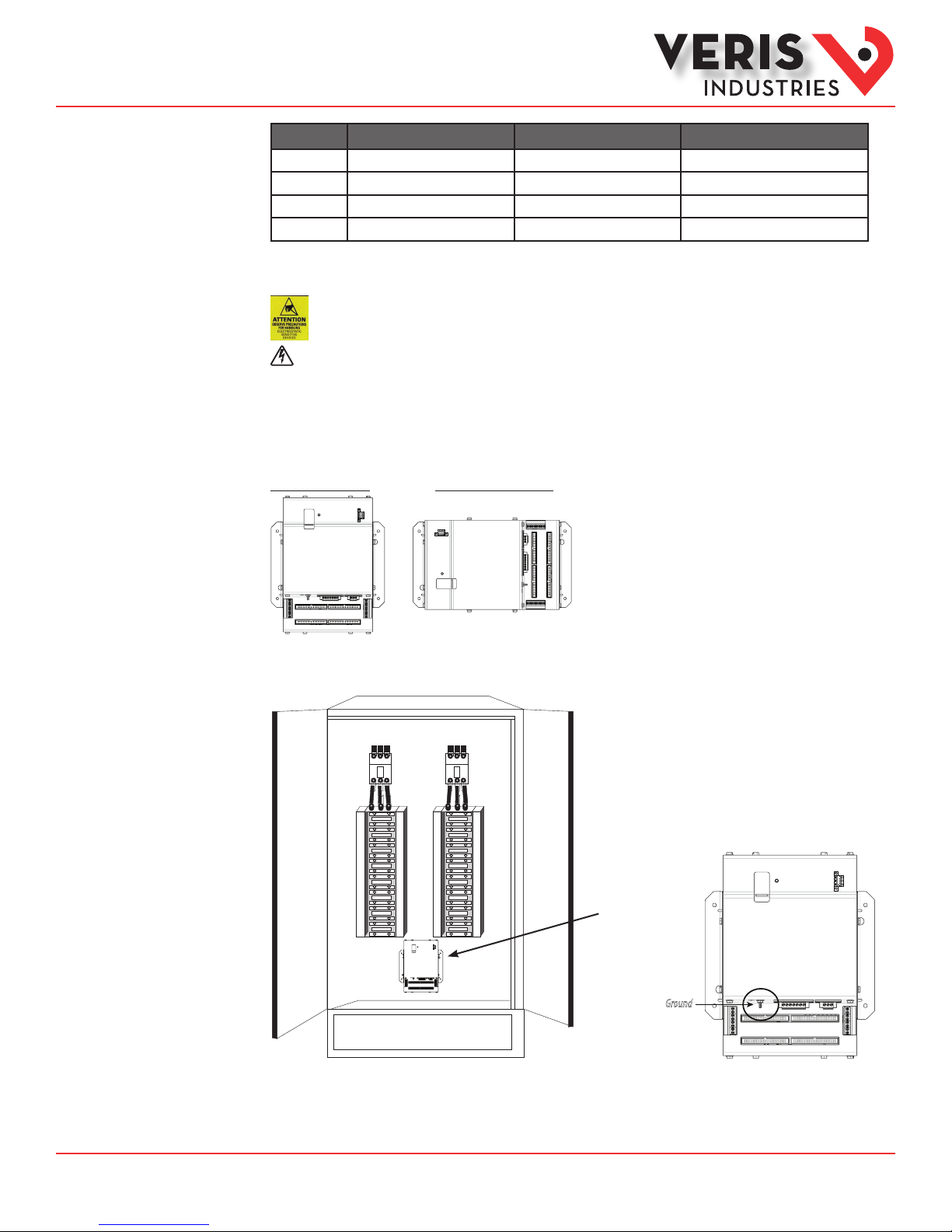
Installation
50 A Split-Core CT 100 A Split-Core CT 200 A Split-Core CT
Voltage Rating 300 VAC 300 VAC (CE), 600 VAC (UL) 300 VAC (CE), 600 VAC (UL)
Accuracy ±1% ±0.5% ±1%
Temperature 0° to 60°C 0° to 60°C 0° to 60°C
Agency UL 61010-1 Recognized, EN61010-1 UL 61010-1 Recognized, EN61010-1 UL 61010-1 Recognized, EN61010-1
Observe precautions for handling static sensitive
devices to avoid damage to the circuitry that
is not covered under the factory warranty.
Disconnect power to the panel before beginning the installation.
1. Locate a surface inside the electrical enclosure to mount the E31E. Decide whether to mount the E31E vertically or horizontally.
The E31E is shipped with the brackets placed for vertical mounting. If mounting horizontally, loosen the screws on the sides of
the E31E that hold the brackets in place (do not fully remove the screws from the E31E housing). Loosen the screws on the other
two sides of the housing (do not fully remove the screws from the E31E housing), and set the brackets into their new positions.
Tighten all screws.
Vertical Mounting Horizontal Mounting
2. Install the E31E in the panel (hardware not provided). A grounding connection is located on the housing (see below). Use this
stud to ground the device when it is mounted on a nonconductive surface.
Panel 2 Panel 1
E31E
CURRENT SENSOR STRIP
CURRENT SENSOR STRIP
CURRENT SENSOR STRIP
CURRENT SENSOR STRIP
Ground
Z206855-0B Page 7 of 26 ©2014 Veris Industries USA 800.354.8556 or +1.503.598.4564 / support@veris.com 04142
Alta Labs, E nercept, Ensp ector, Hawkeye, Trus tat, Aerospo nd, Veris, and th e Veris ‘V’ log o are tradema rks or registe red tradema rks of Veris Ind ustries, L. L.C. in the USA and /or other countri es.
Find Quality Products Online at: sales@GlobalTestSupply.com
Other companies’ trademarks are hereby acknowledged to belong to their respective owners.
www.GlobalTestSupply.com
Installation Guide
Power Monitoring
EESeries
TM
Installation (cont.)
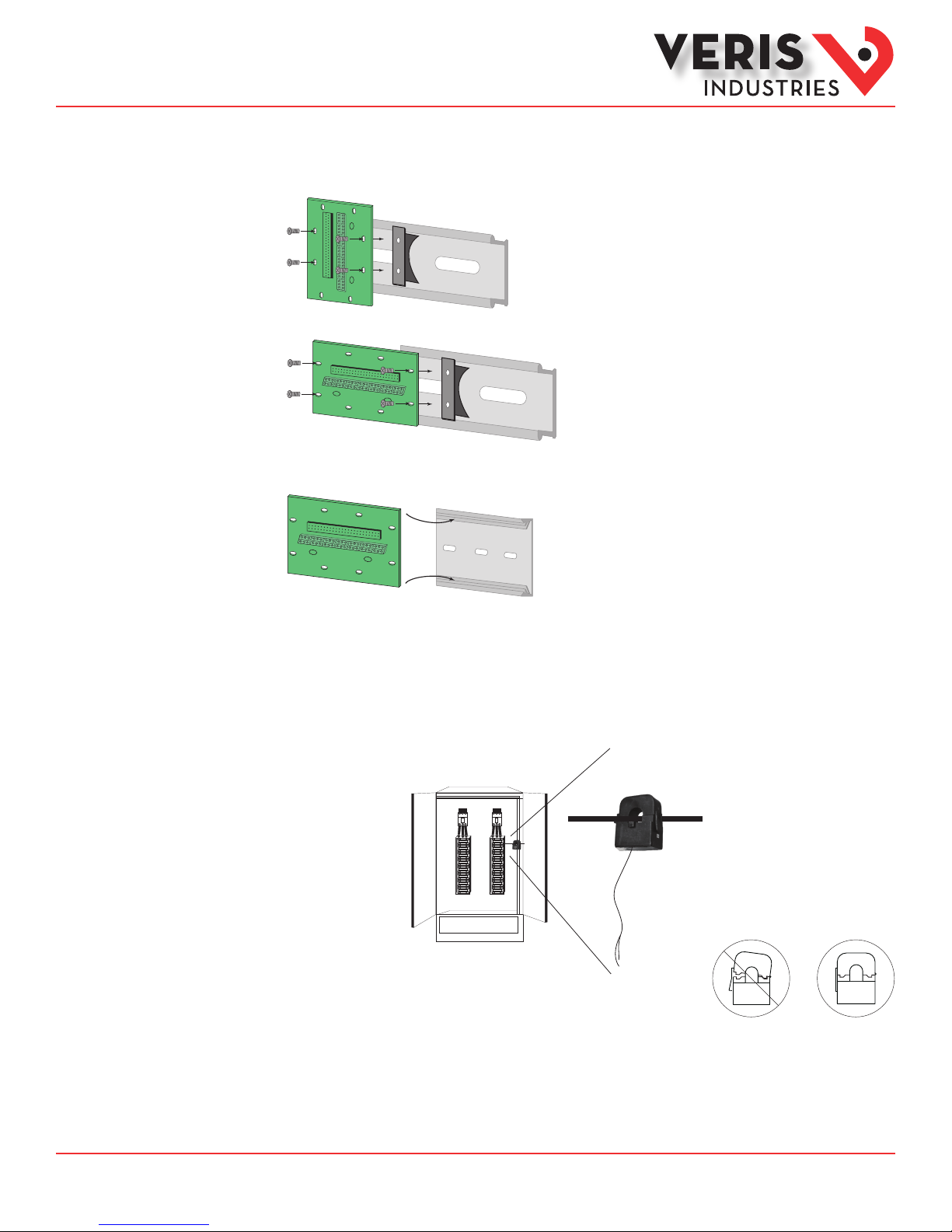
3. Choose a location to mount the adapter boards in the same panel as the E31E. Mount the adapter boards using either DIN rail or
SNAPTRACK.
A. DIN Rail: Use the supplied screws to secure the plastic DIN clip to the adapter board. Ax the clip to the DIN rail.
DIN Option 1: Vertical Mount
DIN Option 2: Horizontal Mount
B. SNAPTRACK: Secure the SNAPTRACK to the mounting surface. Click the adapter board into place.
4. Install the current sensors onto the conductors to be monitored.
Orientation Note: If the signed power factor feature is NOT enabled, then the current sensor orientation does not aect meter
behavior. If this feature IS enabled, orient the current sensors so that the arrow points toward the load for proper operation.
Note: Clean split-core contact surfaces before closing. The hinge can detach, allowing the base and the top to separate for
easier cleaning and installation.
Close current sensors until the clasp
clicks into place to ensure that contact
surfaces are rmly seated.
✓
The 50 A CT accepts a maxim um #2 AWG (0.384” O.D.) wire with THHN insulatio n.
The 100 A CT accepts a maxi mum 3/0 AWG (0.584” O.D.) wire with THHN insulatio n.
The 200 A CT accepts a max imum of 350 MCM wire with THHN insulation.
Z206855-0B Page 8 of 26 ©2014 Veris Industries USA 800.354.8556 or +1.503.598.4564 / support@veris.com 04142
Alta Labs, E nercept, Ensp ector, Hawkeye, Trus tat, Aerospo nd, Veris, and th e Veris ‘V’ log o are tradema rks or registe red tradema rks of Veris Ind ustries, L. L.C. in the USA and /or other countri es.
Find Quality Products Online at: sales@GlobalTestSupply.com
Other companies’ trademarks are hereby acknowledged to belong to their respective owners.
www.GlobalTestSupply.com
 Loading...