

Page 1
FUNCTION TIMING CHART
ON DELAY
INTERVAL
REPEAT CYCLE:
Starting Open
REPEAT CYCLE:
Starting Closed
PULSE
GENERATOR
time
U
R
T
time
U
R
TTTT
OFFONOFF ON
time
U
R
T
time
U
R
TTTT
ON OFFON OFF
Pulse
time
U
R
T
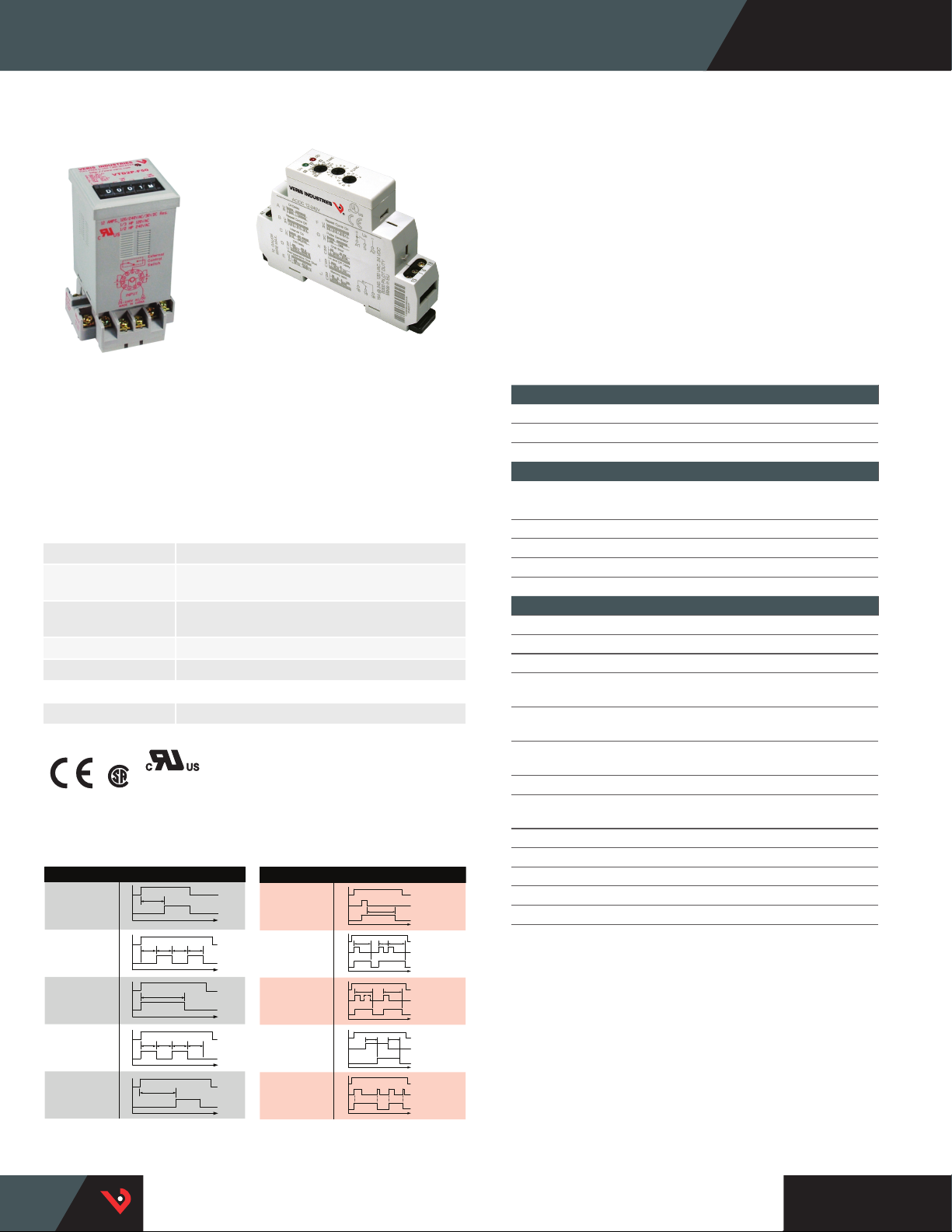
Relays | Time Delay Relays
VTD SERIES
VTD2P-UNI
VTD2P-F50
VBD3P-C
The Veris VTD Series are multi-function time delay relays equipped
with an external control switch input and designed for easy socket/DIN
mounting. The VTD2P-F50 includes five functions shown at left, while
the VTD1P-UNI and VTD2P-UNI include the same five as the VTD2P-F50
plus five more, for the most versatile relay available. Save inventory
costs by purchasing one relay for all the functions you need.
SPECIFICATIONS
Operating Range 85% to 110% of nominal voltage
Drop-Out Voltage
Threshold
Expected Relay Life Electrical (resistive @ rated current) 100,000 cycles;
Dielectric Strength 1000 Vac RMS
Operating Temp Range -20 to 55 °C (-4 to 131 °F)
WARRANTY
Limited Warranty 5 years
AGENCY APPROVALS
*The CE mark indicates RoHS2 compliance.
POWER TRIGGER
REPEAT CYCLE:
REPEAT CYCLE:
Starting Closed
*
FUNCTION TIMING CHART
PULSE
U
R
U
R
U
R
U
R
U
R
ON DELAY
Starting Open
INTERVAL
GENERATOR
15% of nominal voltage
Mechanical (unpowered) 10,000,000 cycles
E198453
E310313
SWITCH TRIGGER
FUNCTION TIMING CHART
OFF DELAY
RETRIGGERABLE
ONE SHOT
ONE SHOT
ON & OFF DELAY
MEMORY LATCH
T
TTTT
OFFONOFF ON
T
TTTT
ON OFFON OFF
T
time
time
time
time
Pulse
time
U
S
R
TT
U
S
R
U
TT
S
R
TT
U
S
R
U
S
R
T
Thumb wheel
adjustment
VTD2P-F50 has thumb wheel
adjustment for function and
Solid state relays
VTD1P/2P-UNI models are made
with solid state relays for greater
reliability
timing accuracy
Housing options
Two different housings provide
multiple mounting options
TYPICAL COIL PERFORMANCE
Power Consumption
AC Coils 1.5 VA
DC Coils 2 w
CONTACT RATINGS
(V TDP-F50)
Resistive 12 A @ 240 Vac, 30 Vdc
Pilot Duty B300
(VTD1p-UNI, VTD2P-UNI)
Resistive 15A @ 240 Vac, 24 Vdc
Motor 1/2 HP @ 120 Vac; 1 HP @ 240 Vac
TIMING CHARACTERISTICS
VTD2P-F50 VTD1P-UNI, VTD2P-UNI
Function Available 5 10
Time Ranges
0.1 se c
sec
0.1 mi n
min
0.1 hr
hr
10 hr 0 to 999 ---
0.1 day
day
Tolerance
(mechanical setting) 0% 5%
Repeatability 0.1% 0.2%
Operate Time
Rest Time
time
time
time
time
time
Trigger Pulse Length (min) --- 50 ms
(max) 25ms no spec
(max) 150 ms 150 ms
0 to 999
0 to 999
0 to 999
0 to 999
0 to 999
0 to 999
---
---
1 to 10
1 to 10
1 to 10
1 to 10
1 to 10
1 to 10
1 to 10
1 to 10
U: Input voltage (power supply) S: Control switch (open or closed)
R: Relay contacts (on or of f) T: Setting time
TM
HQ0001858.F 0117
Page 2
R
1615 18
U
R
2825 26
+
n
-
SA1 A2
-
EXTERNAL
CONTROL
SWITCH
INPUT
VOLTAGE
Relays | VTD Series
VTD1P-UNI/V TD2P-UNI
Dimensional Drawing
VT D1P-UNI
INPUT
VOLTAGE
U
n
+
-
EXTERNAL
CONTROL
SA1 A2
R
1615 18
SWITCH
VTD2P - F50
Wiring Diagram
EXTERNAL CONTROL SWITCH
5
4
3
2
VTD2P-UNI
INPUT
VOLTAGE
U
n
+
-
SA1 A2
R
2825 26
R
1615 18
6
7
10
1
11
15 - COMMON
16 - NORMALLY CLOSED
18 - NORMALLY OPEN
25 - COMMON
26 - NORMALLY CLOSED
28 - NORMALLY OPEN
8
9
VTD2P - F50
Dimensional Drawing
Positive position
thumb wheel
adjustments
RED LED
OUTPUT INDICATOR
A S 0 0 0
1.9"
(48 mm)
VTD1P-UNI/V TD2P-UNI
Dimensional Drawing
3.5”
(90 mm)
1.9"
(48 mm)
3.5"
(89 mm)
1.8"
(45 mm)
PANEL CUTOUT
FOR PANEL MOUNTING
1.4”
(36 mm)
1.8"
(45 mm)
RELAY ORDERING INFORMATION
VTD2P-F50 DPDT 5 12 24 to 240 Vac/dc
VTD1P-UNI SPDT 10 15 24 to 240 Vac/dc Listed •
VTD2P-UNI DPDT 10 15 24 to 240 Vac/dc Listed •
*UL Listed when used with Veris sockets.
SOCKET ORDERING INFORMATION
MODEL RELAY STYLE NO. OF FUNCTIONS AMPERAGE RANGE CO IL VO LTAGE MIN. SWITCHING CURRENT UL CE
MODEL AMPERAGE RATING VOLTAGE RATING UL CE
VBD3P- C 15 A 300 • •
INPUT
0.7”
(18 mm)
VBD3P- C
Dimensional Drawing
2.3"
(58 mm)
100 mA@5 Vdc
When relays and sockets are used together, the
overall amperage rating is the lesser of the two
ratings.
2.6” MAX
(65 mm)
2.1"
(53 mm)
1.0"
(25 mm)
Recognized* •
HQ0001858.F 0117
TM
 Loading...