

Relays |
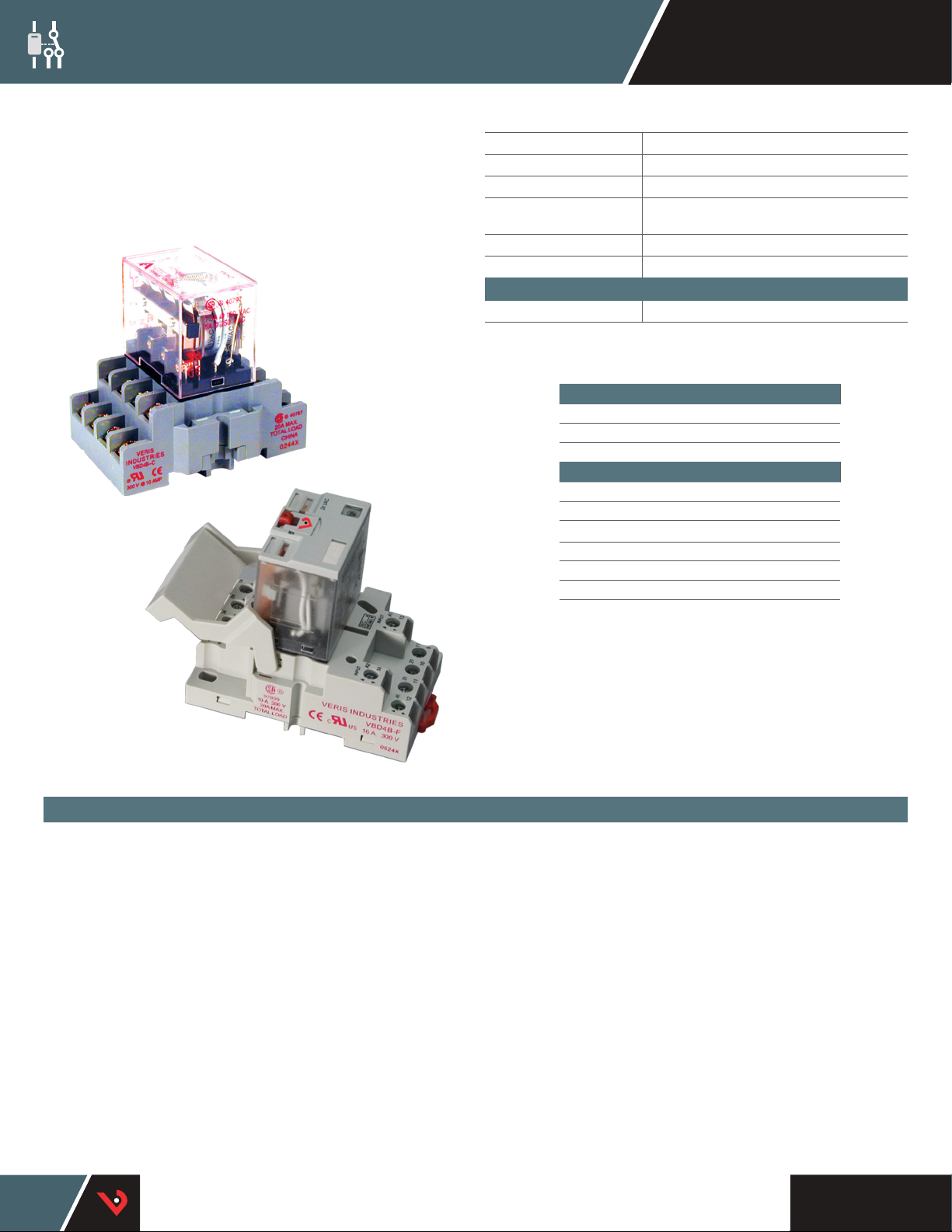
Socket 4PDT Relays
VMD4B &
VMD4B-C Series
VMD4B-C
VBD4B-C
VMD4B-F
SPECIFICATIONS
Operating Temp. Range -40 to 55 °C (-4 0 to 131 °F)
Coil Operating Range 85% to 110% of rated volt age
Coil Drop-out Voltage Threshold 15% of rated volta ge
Expected Relay Life
Operating Time 20 msec typical
Dielectric Strength 1500 Vac RMS
Limited Warranty 5 years
AC Coils 1.5 VA
DC Coils 1.5 W
Resistive 10 A @ 120 Vac
Motor 1/3 HP @ 120 Vac
Pilot Duty B300
Electrical (@ rated current) 100,000 cycles; Mechanical
(unpowered) 10,000,000 cycles
WARRANTY
TYPICAL COIL PERFORMANCE
CONTACT RATINGS
10 A @ 277 Vac
10 A @ 28 Vdc
1/2 HP @ 250 Vac
Power Consumption
VBD4B-F
SOCKET RELAYS IN A WIDE RANGE OF FEATURES AND COIL VOLTAGES
FEATURES
FULL FEATURED MODEL:
• Color-coded push button...allows manual operation of relay. AC coils
red, DC coils blue
• Removable override lever...when activated, locks push button and
contacts in the powered position
• Flag indicator...shows relay status in manual or powered condition
• LED status lamp...shows coil “ON” or “OFF” status
• I.D. tag/write-on plastic label...used for identication of relays in multirelay circuits
• 2-way side or DIN rail mounting system...retrots existing panel
mounting and 35 mm DIN rail
• Mating hold-down clip...secures relay to socket (-F sockets)
DESCRIPTION
The Veris VMD4B Series are 4PDT blade-style relays for socket/DIN
mounting. Both the full-featured and standard DIN rail sockets are
compatible with both the VMD4B-C and VMD4B-F relays and feature a slim,
attractive design.
The standard VMD4B-C model is economical and reliable. The full-featured
VMD4B-F includes an LED and a ag indicator for convenient status viewing
and a push-button test feature for easy troubleshooting. The nger-safe
sockets reduce risk, and the hold-down clip keeps the device secure.
Enhanced safety and dependability.
TM
HQ0001854.E 0116
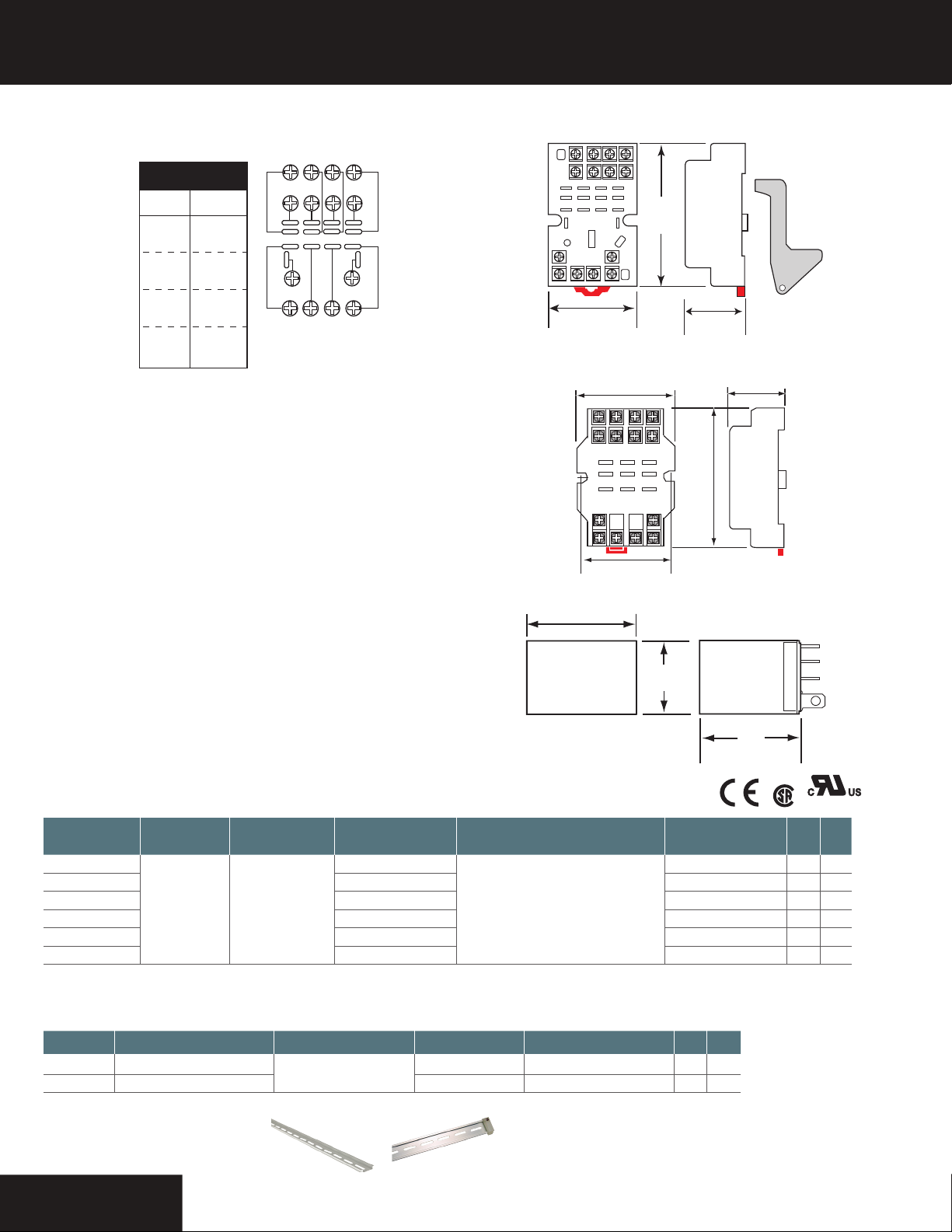
VBD4B Sockets
1.8"
(28 mm)
TOP VIEW
8(44) 7(34) 6(24) 5(14)
4(42) 3(32) 2(22) 1(12)
14 (A2)
12(41) 11(31) 10(21) 9(11)
Coil (+)*
Coil (-)*
COMM1
N.O.1
N.C.1
COMM2
N.O.2
N.C.2
COMM3
N.O.3
N.C.3
COMM4
N.O.4
N.C.4
NEMA (IEC)
Terminal
14 (A2)
13 (A1)
9 (11)
5 (14)
1 (12)
10 (21)
6 (24)
2 (22)
11 (31)
7 (34)
3 (32)
12 (41)
8 (44)
4 (42)
Function
*Observe polarity for relays with DC coil voltages only
13 (A1)
DIMENSIONAL DRAWINGSWIRING DIAGRAM
VBD4B-F Socket
VBD4B-C Socket
2.0"
(51 mm)
2.0"
(51 mm)
3.1"
(80 mm)
Relays | VMD4B & VMD4B-C Series
Hold Down Clip included
with F Model socket
1.1"
1.1"
(28 mm)
2.6"
(66mm)
VMD4B Relays
1.7”
(43 mm)
1.1”
(27 mm)
ORDERING INFORMATION
MODEL
RE LAY
TYPE
VMD4B-C24D
VMD4B-C24A 24 Vac
VMD4B- C120A 120 Va c
VMD4B-F24D 24 Vdc
4PDT 10 A
VMD4B-F24A 24 Va c
VMD4B-F120A 120 Va c
*The CE mark indicates RoHS2 compliance. Note: These relays are UL Listed when used with Veris sockets.
AMPE RAG E
RANGE
24 Vac
COIL
VO LTA GE
MIN. SWITCHING CURRENT FULL FEATURED UL CE
100 mA @5 Vdc
SOCKET ORDERING INFORMATION
MODEL AMPERAGE RATING VOLTAGE RATING FINGER SAFE HOLD DOWN CLIP UL CE
VBD4B-C 10 A
VBD4B-F 16 A
When relays and sockets are used together, amperage rating is the lesser of the two ratings.
300 V
n n n n
n n
1.4”
(36 mm)
*
E198453
E150462
n n
n n
n n
n n n
n n n
n n n
ACCESSORIES
DIN Rail, Stop Clip (AV01, AV02)
HQ0001854.E 0116
AV01
AV02
 Loading...