

Page 1
Temperature Monitoring | Immersion Temperature Sensors
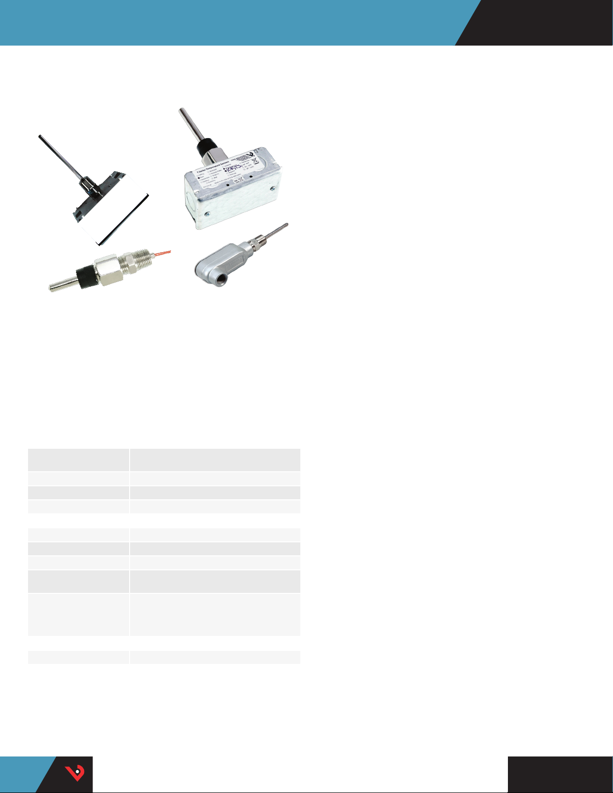
TI SERIES
Corrosion Resistant Stainless Steel Probe
TIW
TID
TIG
TIH
These immersion probe type temperature sensors are both highly
accurate and cost effective. Installation could not be easier. The sensor
is encased in a corrosion-resistant stainless steel probe for durability,
with a choice of service entry body, indoor junction box, or threaded
enclosures. A variety of RTD or thermistor sensor options and probe
lengths are available for maximum application versatility.
Cost effective
Cost-eective, high-accuracy
thermistors/RTDs
Durable
Corrosion resistant stainless steel
probe design
Variety of
enclosures
Duct mount, service entry body,
threaded, and water resistant to
t your application
APPLICATIONS
• Tanks
• Pipes
Easy selection
1/2” NPT threads standard
Easy servicing
Thermowells available
• Chillers
SPECIFICATIONS
Wiring 22 AWG; 2-wire: RTD/Thermistor;
Probe Stainless steel
Test Pressure 200 psi
Operating Temp -25 to 105 °C (-13 to 221 °F)
LINITEMP OPTION
Input Power Class 2; 5 to 30 Vdc
Output 10mV/°C
Operating Temp -25 to 105 °C (-13 to 221 °F)
Calibration Offset 1.5 °C (2.7 °F) typical; 2.5 °C (4.5 °F) max.
Offset Over Temp.
WARRANTY
Limited Warranty 5 years
*Room temperature oset documented on each unit.
3-wire: Linitemp
at 25 °C (77° F)*
1.8 °C (3.24 °F) typical; 3.0 °C (5.4 °F) max.
over 0 to 70 °C (32 to 158 °F) range;
2.0 °C (3.6 °F) typical, 3.5 °C (6.3 °F) max.
over -25 to 105 °C (-13 to 221 °F) range
TM
HQ0001878.K 0117
Page 2

Temperature Monitoring | TI Series
TIG
Dimensional Drawing
TID
Dimensional Drawing
2.2"
(56 mm)
4"
(102 mm)
1.5"
(38 mm)
0.25"Dia.
(6 mm)
1/2" NPT
Standard
L
L
0.5" nom.
(13 mm)
1/2” NPT Standard
TIH
Dimensional Drawing
Immersion Probes
Thermowells
Overall: "L" + 1.75" (45mm)
TIW
Dimensional Drawing
2.8"
(71 mm)
1/2” NPT Standard
0.25" dia.
(6 mm)
L
Overall: "L" + 2" (51 mm)
1/2” NPT Standard
0.375" dia.
(10 mm)
L
4.5"
(114 mm)
1.5"
(38 mm)
1/2" NPT
Standard
ORDERING INFORMATION
Enclosure
TI
D = Duct
G = Servi ce
Entry Body
H = Threade d NPT
Only
W = Water Resis tant
Housing
Probe Length Thermowell Length
A (2 1/2") (64mm) 1 1/2” (38mm)
B (4") (102mm) 3” (76mm)
C (6") (152mm) 5” (127mm)
D (8") (203mm) 7” (178mm)
E (12”) (305mm) 11” (279mm)
* BSPT available with thermowell option only.
** Not avai lable with W and Y high -accuracy th ermistors.
Immersion Probe
Length “L”
A = 2 1/2" (64mm)
B = 4" (102mm)
C = 6" (152mm)
D = 8" (203mm)
E = 12” (305mm)
Thermowell Sizing
Thermowell Sensor Type
0 = None
1 = Add
Thermowell
0.25" dia"
(6 mm)
B = 100R platin um, RTD
C = 1k platinum, R TD
D = 10k T2, Ther mistor
E = 2.2k, T hermistor
F = 3k, The rmistor
G = 10k CPC, The rmistor
H = 10k T3, Ther mistor
I = 1k Balco (Nickel -iron) RTD
J = 10k Dale, The rmistor
K = 10k w/11k shunt, Th ermistor
M = 20k NTC, T hermistor
N = 1800 ohm, Th ermistor
P = 10mV/°C, Linit emp
R = 10k US, Ther mistor
S = 10k 3A221, Thermis tor
T = 100k, Th ermistor
U = 20k “D”, Ther mistor
W = 10k T2 high acc uracy, Thermis tor
Y = 10k T3 high acc uracy, Thermist or
Options
Calibration
Certicate
0 = None
1 = 1-point ca l
validation**
2 = 2-point c al
validation**
Threads
Blank = NP T
A = BSPT*
Example:
TI W D 0 H 0
L
0.25" dia"
(6 mm)
HQ0001878.K 0117
TM
Page 3

Temperature Monitoring | Thermistor Table
THERMISTOR TABLE
Class Pt RTD Balco RTD THERMISTOR
Type 100 Ohm 1000 Ohm 1000 Ohm 10k Type 2 10k Type 3 10k Dale 10k “G” US 20k
Accuracy ±0.3°C ±0.3°C ±1% @70°C ±1.0°C ±0.2°C ±0.2°C ±0.2°C Consult
0.00385
curve
Temp.
Response*
PTC PTC PTC NTC NTC NTC NTC NTC
°C ° F 100 Ohm 1000 Ohm 1000 Ohm 10k Type 2 10k Type 3 10k Dale 10k “G” US 20k NTC
-50 -58 80.306 803.06 740.46 692,700 454,910 672,300 441,200 1,267,600
-40 -40 84.271 842.71 773.99 344,700 245,089 337,200 2 39,700 643,800
-30 -22 88.222 882.22 806.02 180,100 137,307 177,200 135,300 342,000
-20 -4 92.160 921.60 841.00 98,320 79,729 97,130 78,910 189,080
-10 14 96.08 6 960.86 877.46 55,790 47,843 55,340 47,540 108,380
0 32 10 0.000 1,000.00 913.6 6 32,770 29,588 32,660 29,4
10 50 103.903 1,039.03 952. 25 19,930 18,813 19,900 18,78 0 39,440
20 68 107.794 1,077.94 991.82 12,500 12,272 12,490 12,260 24,920
25 77 109.735 1,097.35 1,013.50 10,000 10,000 10,000 10,000 20,00 0
30 86 111.673 1,116.73 1,035.18 8,055 8,195 8,056 8,194 16,14 4
40 104 115.541 1,155.41 1,077.68 5,323 5,593 5,326 5,592 10,696
50 122 119.397 1,193.97 1,120.52 3,599 3,894 3,602 3,893 7,234
60 140 123.242 1,232.42 1,166.13 2,48 6 2,763 2,489 2,760 4,992
70 158 127.075 1,270.75 1,21
80 176 130.897 1,308.97 1,254.55 1,258 1,462 1,258 1,458 2,516
90 194 134.707 1,347.07 1,301.17 919 1,088 917 1,084 1,833
100 212 138.506 1,385.06 1,348.38 682 821 679 816.8 1,356
110 230 142.293 1,422.93 1,397.13 513 628 511 623.6 1,016
120 248 146.068 1,460.68 1,4 47.44 392 486 389 481.8 770
130 266 149.832 1,498.32 1,496.28 303 380 301 376.4 591
Sensor
Codes
0.00385
curve
-50/150°C 0/70°C -20/70°C 0/70°C Factory
STANDARD RTD AND THER MISTOR VALUES (Ohms Ω)
90 64,160
0.75 1,753 1,994 1,753 1,990 3,512
B C I D H J R M
Accessories | C Series
To compute Linitemp Temperature
mV read ing /10 - 273.15 = Temperature in °C
HQ0001878.K 0117
HQ0001874.H 0117
TM
 Loading...