

Page 1
Temperature Monitoring | Wall Mount Temperature Sensors
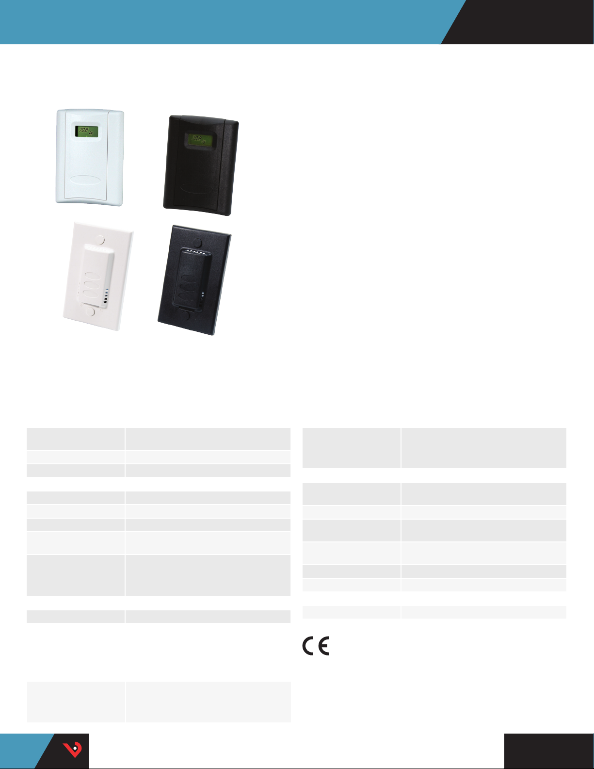
TW & TE SERIES
Wall Mount Temperature Sensors
TW
TE
These wall mounted temperature sensors feature a discreet appearance
combined with high accuracy and reliability. Aesthetically pleasing in
any interior environment. Flexible mounting options include flush and
single-gang for ease of installation.
Wall mount
Low-prole housing
APPLICATIONS
• Controlling HVAC systems for
improved comfort & energy
savings
• Museums, schools, printing
shops, hospitals, data centers,
& other locations that require
temperature control
Quick installation
Reduced downtime for deployment
• Facilitating compliance with
ASHRAE standards for
environmental control and
indoor air quality
SPECIFICATIONS
TE Series
Wiring 22 AWG; 2-wire: RTD Thermistor, 4 to 20 mA;
Housing Black or white ABS plastic
Operating Temp -25 to 105 °C (-13 to 221 °F)
LINITEMP OPTION
Input Power Class 2; 5 to 30 Vdc
Output 10 mV/°C
Operating Temp -25 to 105 °C (-13 to 221 °F)
Calibration Offset 1.5 °C (2.7 °F) typ.; 2.5 °C (4.5 °F) max. at 25 °C
Offset over Temp
WARRANTY
Limited Warranty 5 years
3-wire: voltage output models
(77 °F)*
1.8 °C (3.24 °F) typical; 3.0°C (5.4 °F) max. over
0 to 70 °C (32 to 158 °F) range;
2.0 °C (3.6 °F) typical, 3.5 °C (6.3 °F) max. over
-25 to 105 °C (-13 to 221 °F) range
SPECIFICATIONS
TW/TEA Series
INPUT POWER
TW Model 4 to 20mA mode: loop powered Class 2, 12 to 30
Vdc only, 30 mA max.;
0-5/0-10 V mode: Class 2, 12 to 30 Vdc/24 Vac,
50/60 Hz, 15 mA max.
TEA Model 4 to 20 mA mode; loop powered Class 2; 24 Vdc
RANGES
TW Model 10 to 35 °C (50 to 95 °F)/0 to 50 °C (32 to 122 °F)
TEA Model 10 to 35 °C (50 to 95 °F)
Analog Output
TEA 4 to 20 mA model
Temp Output
TW Model
Transmitter Type Solid-state, integrated circuit
Transmitter Accuracy ±0.5 °C (±.9 °F) typical
WARRANTY
Limited Warranty 5 years
AGENCY APPROVALS
**
Note: RTD/ Thermistors in wall packages are not compensated for internal heating of
product.
*Room temperature oset documented on each unit.
**The CE mark indicates RoHS2 compliance. Please refer to the CE Declaration of
Conformity for additional details.
only; 0-10 V, 3-wire, observe polarity; 12-30 Vdc;
0-5 V, 3-wire, observe polarity; 24 Vac, 50/60 Hz,
12-30 Vdc
jumper-selectable
2-wire, not polarity sensitive (clipped & capped)
2-wire, loop powered 4 to 20 mA or 3-wire,
0-5 V/0 - 10 Vdc
TM
HQ0001876.H 0117
Page 2
32° to 122°
50° to 95°
0° to 50°
10° to 35°
Temp Range
10V
5V
Voltage Range
°C
°F
Temp Scale
Temperature Monitoring | TW & TE Series
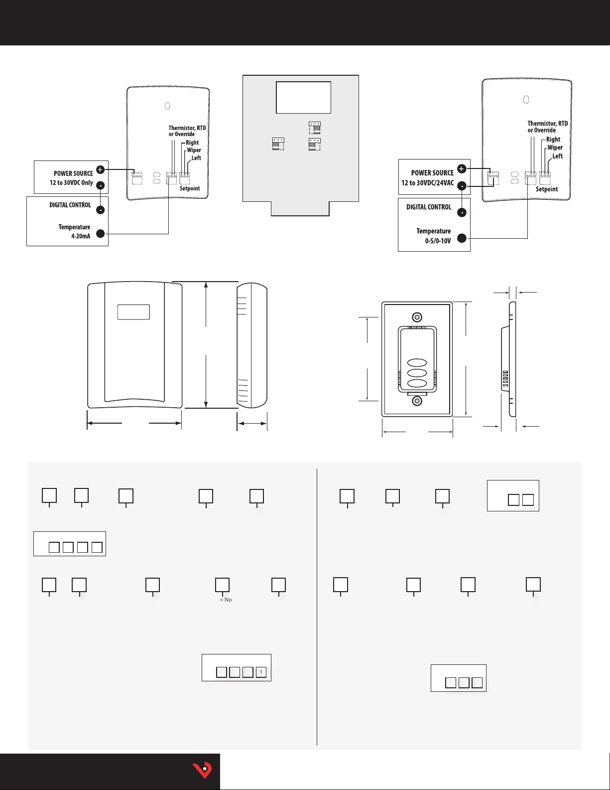
TW (4 TO 20 MA)
Wiring Diagram
TW
Dimensional Drawing
4.8"
(122 mm)
TE/TEA
Dimensional Drawing
3.2"
(82 mm)
TW (0-5/0-10 V)
Wiring Diagram
NOTE: For 24 Vac transformer
powered applications, one
side of transformer secondar y
is connected to common.
Isolation transformer, or
dedicated power supply may
be required.
0.25"
(6 mm)
4.5"
(115 mm)
ORDERING INFORMATION
Sensor
Typ e
A
L = LCD
X = No
= Transmitte r
selectable
outputs
Sensor
Typ e
B = 100R platinum, RT D
C = 1k platinu m, RTD
D = 10k T2, Thermist or
E = 2.2k, T hermistor
F = 3k, Thermist or
G = 10k CPC, Thermis tor
H = 10k T3, Thermisto r
I = 1k Balco (Ni ckel-iron) RTD
J = 10k Dale, Thermis tor
K = 10k w/11k shunt, Thermi stor
M = 20k NTC, Therm istor
N = 1800 ohm, Thermi stor
P = 10mV/°C, L initemp
R = 10k US, Thermisto r
S = 10k 3A221, Thermistor
T = 100k, Thermi stor
U = 20k “D”, Thermisto r
W = 10k T2 high accurac y, Thermistor
Y = 10k T3 high accurac y, Thermistor
TW
Example:
TW X A 0 2
TW
L = LCD
X = No
Local
Display
Local
Display
3.5"
(89 mm)
Setpoint/
Override
0 = None
2 = 1k Setpoint
3 = 10k Setpoi nt
4 = 1k Setpoint w/over ride
5 = 10k Setpoi nt w/override
Setpoint/
Override
0 = None
1 = Override*
2 = 1k Setpoint
3 = 10k Setpoi nt
4 = 1k Setpoint w/over ride*
5 = 10k Setpoi nt w/override*
1.2"
(31 mm)
Cal
Housing
Color
None = Clo ud White
B = Black
Housing
None = Clo ud White
B = Black
Cal
Certicate
0 = None
1 = 1 point
Cal validation
2 = 2 point
Cal validation
Certicate
0 = None
1 = 1 point
Cal validation
2 = 2 point
Cal validation
Example:
TW L C 0 1
*Pushbut ton override sho rt circuits
RTD/thermistor output.
** Not avai lable with W and Y high accuracy thermistors.
Color
Output US or EU
TEA
M = 4 to 20 mA
V = 0-10 Vdc
J = 0-5 Vdc
Sensor
Typ e
TE
B = 100R platinum, RT D
C = 1k platinu m, RTD
D = 10k T2, Thermist or
E = 2.2k, Ther mistor
F = 3k, Thermist or
G = 10k CPC, Thermis tor
H = 10k T3, Thermisto r
I = 1k Balco (Ni ckel-iron) RTD
J = 10k Dale, Thermis tor
K = 10k w/11k shunt, Thermi stor
M = 20k NTC, Therm istor
N = 1800 ohm, Thermi stor
P = 10mV/°C, L initemp
R = 10k US, Thermisto r
S = 10k 3A221, Thermistor
T = 100k, Thermi stor
U = 20k “D”, Thermisto r
W = 10k T2 high accurac y, Thermistor
Y = 10k T3 high accurac y, Thermistor
S
= Standard
2.8"
(72 mm)
Housing Color
None = Clo ud White
B = Black
Setpoint/
Override
0 = None
1 = Override*
2 = 1k Setpoint
3 = 10k Setpoi nt
4 = 1k Setpoint
with override*
5 = 10k Setpoi nt
with override*
Example:
TE D 5 2
*Pushbut ton override sh ort circuits RT D/thermistor
output
** Not avai lable with W and Y high -accuracy th ermistors.
Cal
Certicate
0 = None
1 = 1-point
cal validation**
2 = 2-point
cal validation**
0.5"
(13 mm)
Example:
TEA J S
None = Cloud white
B = Black
Housing
Color
HQ0001876.H 0117
TM
Page 3

Temperature Monitoring | Thermistor Table
THERMISTOR TABLE
Class Pt RTD Balco RTD THERMISTOR
Type 100 Ohm 1000 Ohm 1000 Ohm 10k Type 2 10k Type 3 10k Dale 10k “G” US 20k
Accuracy ±0.3°C ±0.3°C ±1% @70°C ±1.0°C ±0.2°C ±0.2°C ±0.2°C Consult
0.00385
curve
Temp.
Response*
PTC PTC P TC NTC NTC NTC NTC NTC
°C °F 100 Ohm 1000 Ohm 1000 Ohm 10 k Type 2 10k Type 3 10k Dale 10k “G” US 20k NTC
-50 -58 80.306 803.06 740.46 692,700 454,910 672,300 4 41,200 1,267,600
-40 -4 0 84.271 842.71 773.99 34 4,700 245,089 337,200 239,700 643,800
-30 -22 88.222 8 82.22 806.02 180,100 137,307 177,200 135,300 342,000
-20 -4 92.160 921.60 841.00 98,320 79,729 97,130 78,910 189,08 0
-10 14 96.086 96 0.86 877.46 55,790 47,843 55,340 47,540 108,380
0 32 100.000 1,000.00 913.66 32,770 29,588 32,660 29,4
10 50 103.9 03 1,039.03 952.25 19,930 18,813 19,900 18,780 39,440
20 68 107.794 1,077.94 991.82 12,500 12,272 12,490 12,260 24,920
25 77 109.735 1,097.35 1,013.50 10,0 00 10,000 10,0 00 10,00 0 20,000
30 86 111.673 1,116.73 1,035.18 8,055 8,195 8,056 8,194 16,144
40 104 115.541 1,155.41 1,077.68 5,323 5,593 5,326 5,592 10,696
50 122 119.397 1,193.97 1,120.52 3,59 9 3,894 3,602 3,893 7,234
60 140 123.242 1,2 32.42 1,166.13 2,486 2,763 2,489 2,760 4,992
70 158 127.075 1,270.75 1,21
80 176 130.897 1,308.97 1,254.55 1,258 1,462 1,2 58 1,458 2,516
90 194 134.707 1,347.07 1,301.17 919 1,088 917 1,084 1,833
100 212 138.506 1,385.0 6 1,34 8.38 682 821 679 816.8 1,356
110 230 142.293 1,422.93 1,397.13 513 628 511 623.6 1,016
120 248 146.068 1,460.68 1,447.44 392 4 86 389 481.8 770
130 266 149.832 1,498.32 1,496.28 303 380 301 376.4 591
Sensor
Codes
0.00385
curve
-50/150°C 0/70°C -20/70°C 0/70°C Factory
STANDARD RTD AND THERMISTOR VALUES (Ohms Ω)
90 64,160
0.75 1,753 1,994 1,753 1,990 3,512
B C I D H J R M
Accessories | C Series
To compute Linitemp Temperature
mV rea din g/10 - 273.15 = Temperature in °C
HQ0001876.H 0117
HQ0001874.H 0117
TM
 Loading...