

Page 1
TM
EnvironmEntal SEnSorS
inStallation GUiDE
PD SerieS
NOTICE
• This product is not intended for life or safety applications.
• Do not install this product in hazardous or classified locations.
• Read and understand the instructions before installing
this product.
• Turn off all power supplying equipment before working on it.
• The installer is responsible for conformance to all applicable codes.
PD SerieS
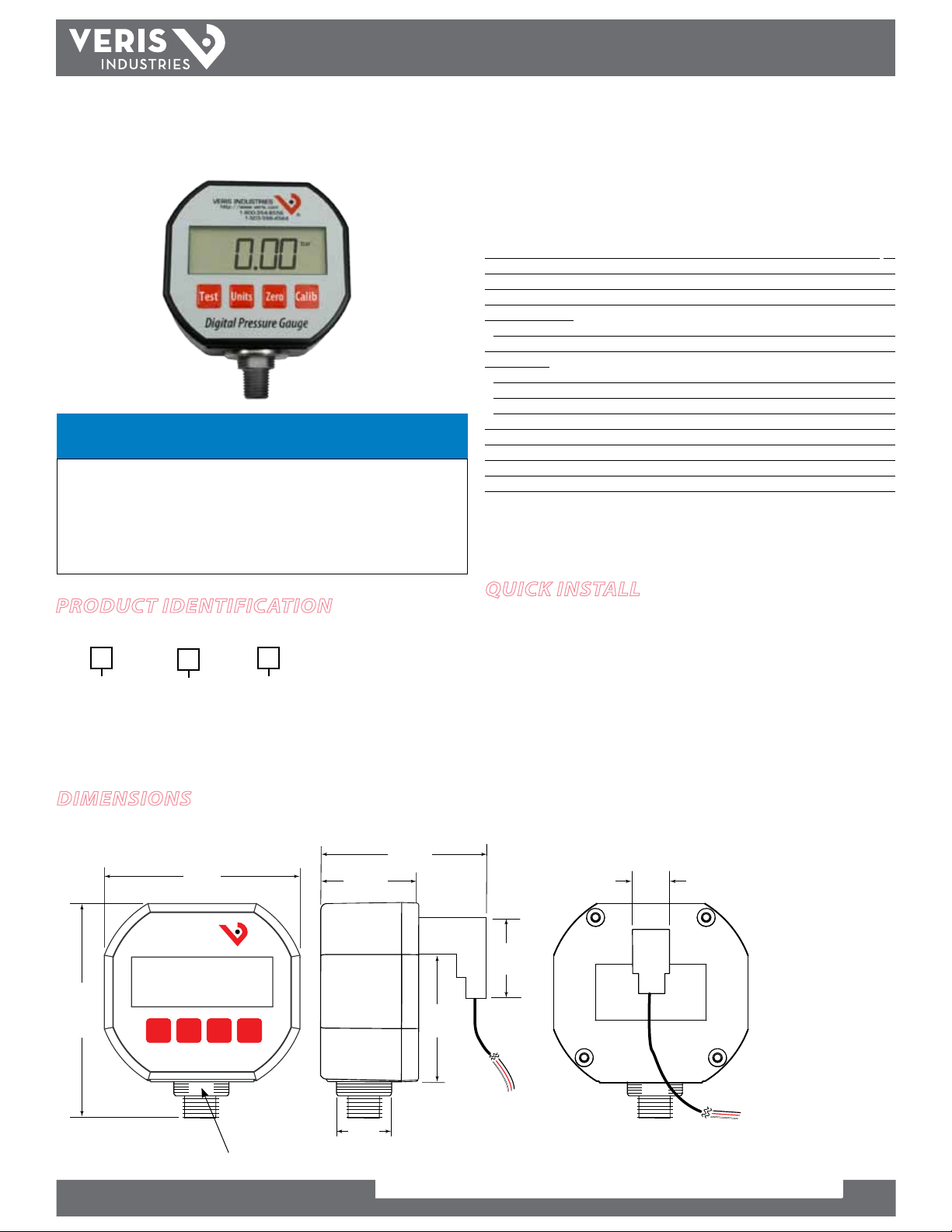
Digital Pressure/Vacuum Gauge with Display
and Analog 4-20 mA Output
Installer’s Specifications
Measurement Units Select able: psi, bar, kg/cm2, ATM, in. Hg, in. H2O*
Accuracy** < ±0.5% of F.S., BFLS
Overange Protection 2x rated pre ssure
Burst Pre ssure 5x rated pressure or 5000 psi, whichever is less
Temperature Ranges:
Operating (Ambient) -10° to 70°C (15° to 158°F)
Storage -40° to 65°C (-4 0° to 150°F)
Thermal Limits:
Compensated Range 0° to 55°C (32° to 131°F)
TC Zero < ±1.5% of F.S.
TC Span < ±1.5% of F.S.
Connection ¼" NPT, male
Power*** 7.5 to 32 VDC
Housing Polycarbonate
Environmental Protec tion NEMA 4, IP65
Output 4-20 mA loop powered
* in. H2O units available on ≤250 psi range devices only
** Accuracy includes non-linearity, hysteresis and non-repeatability measured at 25°C/77°F
*** Select a loop p ower supply and total loop resistance such that when the loop current is 20 mA,
the gauge will have at least 7.5 VDC at its terminals.
ProDuct iDentification
Range
Material
PD A M
50 = 0 to 50 psig
100 = 0 to 100 psig
250 = 0 to 250 psi g
500 = 0 to 500 ps ig
1000 = 0 to 1000 ps ig
= 17 - 4 SS
Output
= 4-20 mA
Dimensions
Front Side Rear
3.6”
(90mm)
VERIS INDUSTRIES
http://www.veris.com
1-800-354-8556
1-503-598-4564
4.2”
(106mm)
Test Units
Zero
Calib
1.8”
(46mm)
2.8”
(72mm)
quick install
1. Select a location for the installation suitable to the gauge’s physical dimensions
that will allow access to the display and keypad. Plan for a ¼" M-NPT connection
or a hose to a ¼" tting.
2. Thread the gauge onto the tting. Apply tightening torque only to the metal
wrench ats, not to the PD housing. Use a 5/8” wrench. Do not overtighten.
3. Wire the device. See the wiring diagram in this guide.
4. Remove the protective lm from the gauge front.
5. Program the gauge.
0.7”
(17mm)
1.4”
(36mm)
2.2”
(56mm)
Digital Pressure Gauge
(Tighten with a 5/8” wrench at this spot. Do not tighten by t wisting the plastic PD housing.
5/8”
Wrench Flat
ZL0055-0D PAGE 1 ©2012 Veris Industries 07121
Alta Labs, Enercep t, Enspector, Hawkeye, Trustat, Veris, and the Veris ‘ V’ logo are trademark s or registered tradema rks of Veris Industries, L.L .C. in the USA and /or other count ries.
Page 2
TM
PD SEriES
inStallation GUiDE
DescriPtion
PD analog digital pressure gauges are media isolated, so they can be used with any
gas, liquid, or solid compatible with 17-4 PH stainless steel within the specied
pressure range. The transducer consists of a one-piece, high-strength pressure sensor
that uses no silicone oils, welds, O-rings, or seals. The sensor is coupled to a 4-20 mA
loop powered internal display and keypad. The keypad controls setup and operation
of the sensor as described below.
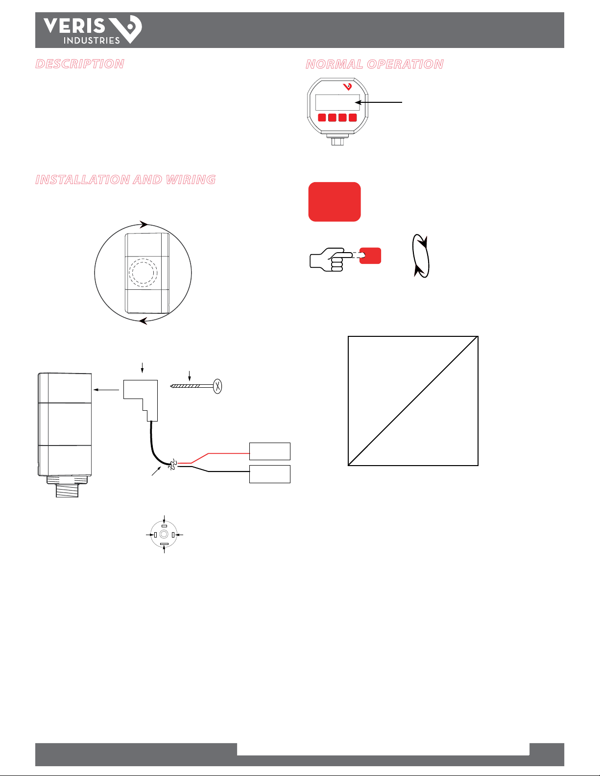
installation anD Wiring
Allow space to turn the PD Analog onto the pipe or tting during mounting. The PD is
delivered with the connector attached to the device.
4.25”
108mm
+
normal oPeration
VERIS INDUSTRIES
http://www.veris.com
1-800-354-8556
®
1-503-598-4564
Pressure readin g appears in the
Test Calib
Units Zero
Digital Pressure Gauge
selected units (PSI, bar, etc.)
To select/change display units:
Units
Units
Output signal:
10 V/5 V
PSI
bar
Atm
kg/cm²
in. Hg
in. H2O
Volt
Note: The UNITS button
does not aect the mA
output.
connector
15’ lead
Pin 2
Pin 3
Wide Pin
locking screw
Pin 1
red
black
Pin 2 = 4-20mA output
Pin 3 = +V
supply voltage
7.5 to 32 VDC
control panel
4-20 mA input
Electrical
Select a loop power supply voltage and total loop resistance such that when the loop
current is 20 mA, the gauge will have at least 7.5 VDC at its terminals. Too large a loop
resistance will cause the gauge output to "limit" or saturate before reaching its full
20 mA output.
0 V
Output Signal
zero/low-end
pressure
Pressure Readi ng
Note: For out-of-scale
pressure read ings,
output can go as low
as 3.5mA or as high as
24m A.
full-scale/high-end
pressure
The minimum loop supply voltage is calculated from the formula:
V
= 7.5V + (20mA * total loop resistance).
min
If the loop voltage drops too low, the PDxAM will display the LOW LOOP icon. At this
time, all calibration functions are disabled.
The LCD is loop-powered. If no voltage is applied, or if the connector is removed, the
display will be blank.
ZL0055-0D PAGE 2 ©2012 Veris Industries 07121
Alta Labs, Enercep t, Enspector, Hawkeye, Trustat, Veris, and the Veris ‘ V’ logo are trademark s or registered tradema rks of Veris Industries, L.L .C. in the USA and /or other count ries.
Page 3

TM
Units
Calib
Test
Current
measurement
device
Calib
Units
OR
PD SEriES
inStallation GUiDE
test
To switch the PD into Test Mode, press and hold down the TEST button. The Test Mode
allows setup and testing of the output voltage without altering the system pressure.
To change the test output level, press and hold the TEST button, and press the CALIB
button while holding TEST. Each time the CALIB button is pressed, the test level
output increases by 2 mA.
VERIS INDUSTRIES
http://www.veris.com
1-800-354-8556
Test Calib
Units Zero
Digital Pressure Gauge
1-503-598-4564
®
Press and hold to enter Test Mode.
To change test output level, press
CALIB while holding TEST.
zero Pressure calibration
Press ZERO then CALIB.
VERIS INDUSTRIES
http://www.veris.com
1-800-354-8556
1-503-598-4564
®
Hold both for 3 seconds.
Release when display reads zero
pressure.
sPan Pressure calibration
Units
Calib
Calib
Notes:
Only attempt Span ca libration if the user has access to a pressure reference of known accuracy. Use
calibration equipment swith at least four times the gauge accuracy. Perform Zero calibration
before span calibration.
If the user tries to calibrate the unit beyond ±10% of the factory calibratio n, the display will read
“ERR” indicating an erroneous calibration.
To cancel calibration, press and release the CALIB button.
To restore factory calibration, repeat steps 1 and 2, then h old the ZERO button for 3 seconds, u ntil
the display reads “FAC.”
1. Press to select pressure units.
2. Press and hold for 3 seconds, until display alternately
reads “CAL” and the calibration pressure (e.g. “CAL” and
“500” to calibrate at 500 psi).
3. Connect the gauge port to a pressure reference of known
accuracy. Apply pressure level selected in Step 2.
4. Press and hold the CALIB button for 3 seconds until
display reads “DONE.” Calibration is now complete.
Test Calib
Units Zero
Digital Pressure Gauge
Open gauge por t.
The PD can be re-zeroed without aecting the span calibration. The gauge port must
be open with no pressure or vacuum applied.
Perform this step when pressure uni ts show in the display (not mA). Zero calibration is retained
after unit is turned o .
current outPut calibration
The current output on the PD analog pressure gauge has been set at the factory.
These setting will not normally need adjustment. Perform these steps only if
necessary.
1. Press to select the mA units.
2. Connect the leads to an accurate current measurement
device.
3. Press and hold for 3 seconds, until the display ashes
between “CAL” and “4.00.” Set the loop current to 4.00
mA
4. Press TEST to decrease the output by 0.01 mA. Press UNITS
to increase the output. While the output will change, the
display will not.
5. Press and hold for 3 seconds to accept the calibration at
4.00 mA. The display will change to “CAL” and “20.00.”
6. Repeat steps 3 through 5 to calibrate at 20 mA. Display will now read “DONE.”
Notes:
To cancel calibration changes, briey press and rel ease the CALIB button.
To restore factory calibration, repeat step 3 on ly, then hold the ZERO button for 3 seconds, unti l the
display reads “ FAC.”
ZL0055-0D PAGE 3 ©2012 Veris Industries 07121
Alta Labs, Enercep t, Enspector, Hawkeye, Trustat, Veris, and the Veris ‘ V’ logo are trademark s or registered tradema rks of Veris Industries, L.L .C. in the USA and /or other count ries.
 Loading...