

Page 1
Setpoint Devices | Wall Mount Humidity Transmitter
Thermostat Humidistat Functions
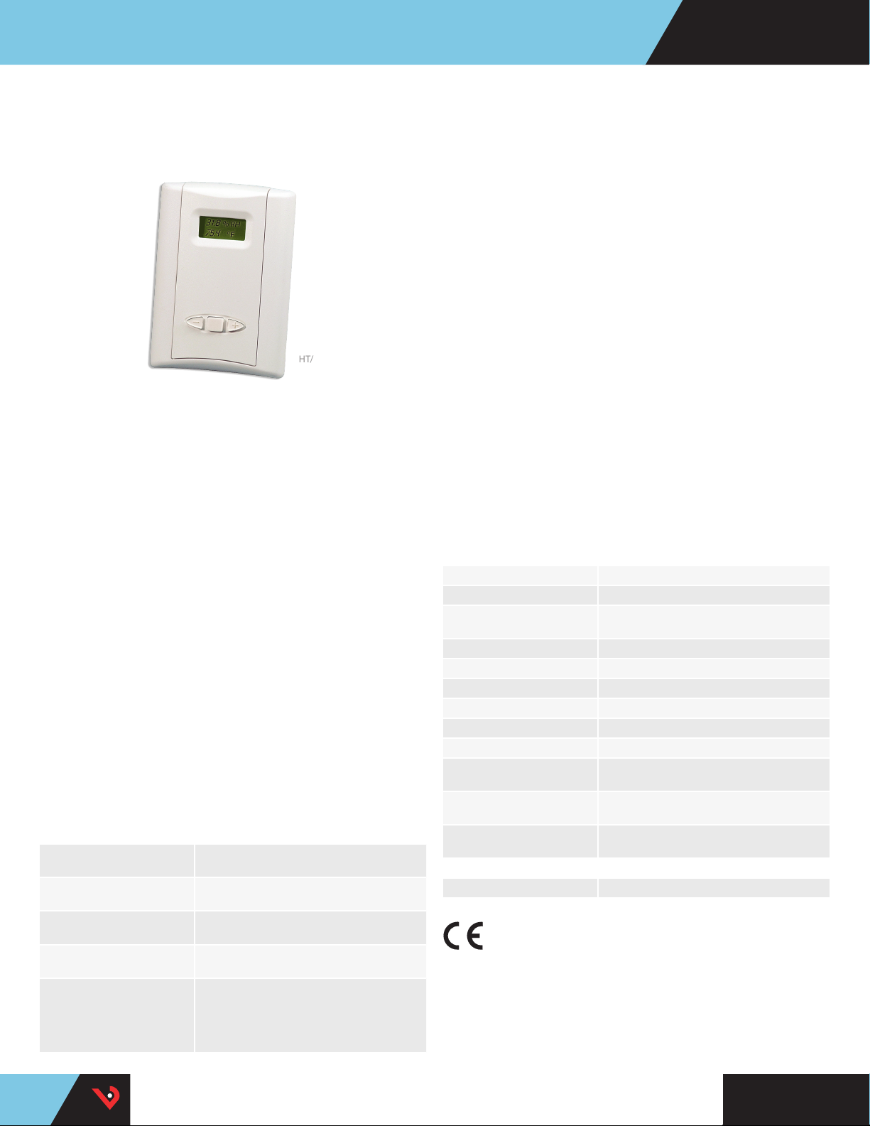
HT/HWS SERIES
Independent RH, Temp, and Analog Setpoint
Outputs
HT/ HWS
All HT/HWS Series institutional grade relative humidity transmitters
are designed to meet the rigorous needs of pharmaceutical labs,
hospitals, science labs, and other settings that call for precise
environmental control. Internal jumpers control access to a feature that
allows adjustment of the calibration offsets. The devices can also be
made tamper resistant using a jumper to disable keypad programing
functions. HT/HWS models are calibrated with NIST traceable calibration
equipment.
Analog Output Transmitter
Analog output models feature a keypad to make adjusting humidity
and temperature setpoint values easy. They transmit the setpoint values
back to a control system by means of dual outputs. A slide-switch allows
easy selection of output type, either 4 to 20 mA or 0 to 5 V/0 to 10 Vdc
signals. Dual outputs enable effortless control of both humidity and
temperature in a single, compact sensor.
Setpoint Relay Transmitter
The HT Series setpoint relay models also offer thermostat or humidistat
functionality. Two separate relays can be configured to control heating
and cooling when in thermostat mode, or humidifying and dehumidifying when in humidistat mode.
HWS models offer the same precise humidity measurement and control
as the HT, but without the temperature and thermostat features.
SPECIFICATIONS
Input Power Class 2; 15 to 30 Vdc or 24 Vac 50/60Hz, 100
Outputs, Analog Switch-selectable 4 to 20 mA, or 0 to 10 V/
Outputs, Relay (Relay models
only)
RH Sensor Digitally profiled thin-film capacitive
Accuracy at 25 °C from 10 to
80% RH**
(Multi-point calibration NIST
traceable)
mA max.
0 to 5 Vdc (switch affects both outputs)
2 Form C (SPDT), 1A 30VDC, resistive, 30 W
max.
(32-bit mathematics) U.S. Patent 5,844,138*
±2%, 3%, or 5% models; ±1% at 20 to 50% RH
on HTA models
±1% at 12 to 40% RH on HTR models in mA
output mode; ±1% at 30% RH on HTR models
in voltage output mode
Flexibility
Independent heat/cool (TWS
relay) or analog setpoint outputs
(TWS analog) provide application
exibility
LCD display
LCD for local display of readings
and setup values
Offset function
Offset function adjusts calibration
intervals for both RH and T
(HT models)
Switchselectable
Switch-selectable 4 to 20 mA or
0 to 5/0 to 10 Vdc analog outputs
Multi-point
calibration
Multi-point calibration to 1% RH,
traceable to NIST
Saves time
Replaceable RH sensor element
supports field calibration offset
APPLICATIONS
• Hospitals and operating rooms,
pharmaceutical labs
• Clean rooms
Reset Rate*** 24 hours
Stability ±1% @ 20 °C (68 °F) annually, for two years
Hysteresis RH: 1.5% (typical),
Linearity Included in accuracy spec.
Operating Humidity Range 0 to 100% RH non-condensing
Temperature Coefficient ±0.1%RH/°C above or below 25 °C (typical)
Operating Temperature Range 10 to 35 °C (50 to 95 °F)
Temperature Accuracy ±1.0 °C (±1.8 °F)
Physical UL 94V-0 fire retardant ABS
Scaling RH: 0 to 100%; Temp: 10 to 35 °C (50 to 95 °F)
Calibration Offset RH: Adjustable ±10% in 0.1% increments;
Setpoint Range RH: 10 to 80% in 1% increments;
WARRANTY
Limited Warranty 5 years
AGENCY APPROVALS
****
* The HS sensing element has a 1-year warranty. The element is not included in the 5-year
product warranty.
** Specified accuracy with 24 Vdc supplied power with rising humidity.
***Reset rate is time required to recover to 50% RH after exposure to 90% RH for 24 hours.
One side of transformer secondary is connected to a signal common, so an isolation
transformer or dedicated power supply may be required.
RTD/thermistors in wall packages are not compensated for internal heating of product.*The
****CE mark indicates RoHS2 compliance. Please refer to the CE Declaration of Conformity
for additional details.
• Food processing plants
• Environmental testing facilities
and other institutional
applications
Temp: 1 to 10 °F in 1 °F increments
or 0 to 50 °C (32 to 122 °F) menu selectable
Temp: Adjustable ±10° in 0.1° increments
Temp: minimum to full scale in 1 °F increments
TM
HQ0001872.F 0117
Page 2
(29 mm)
RH
SENSOR
TEMP
SENSOR
RH
YES
AMPVOLT
NO YES
RUN
CAL
NO
TEMP
–
Minus PlusEnter
+
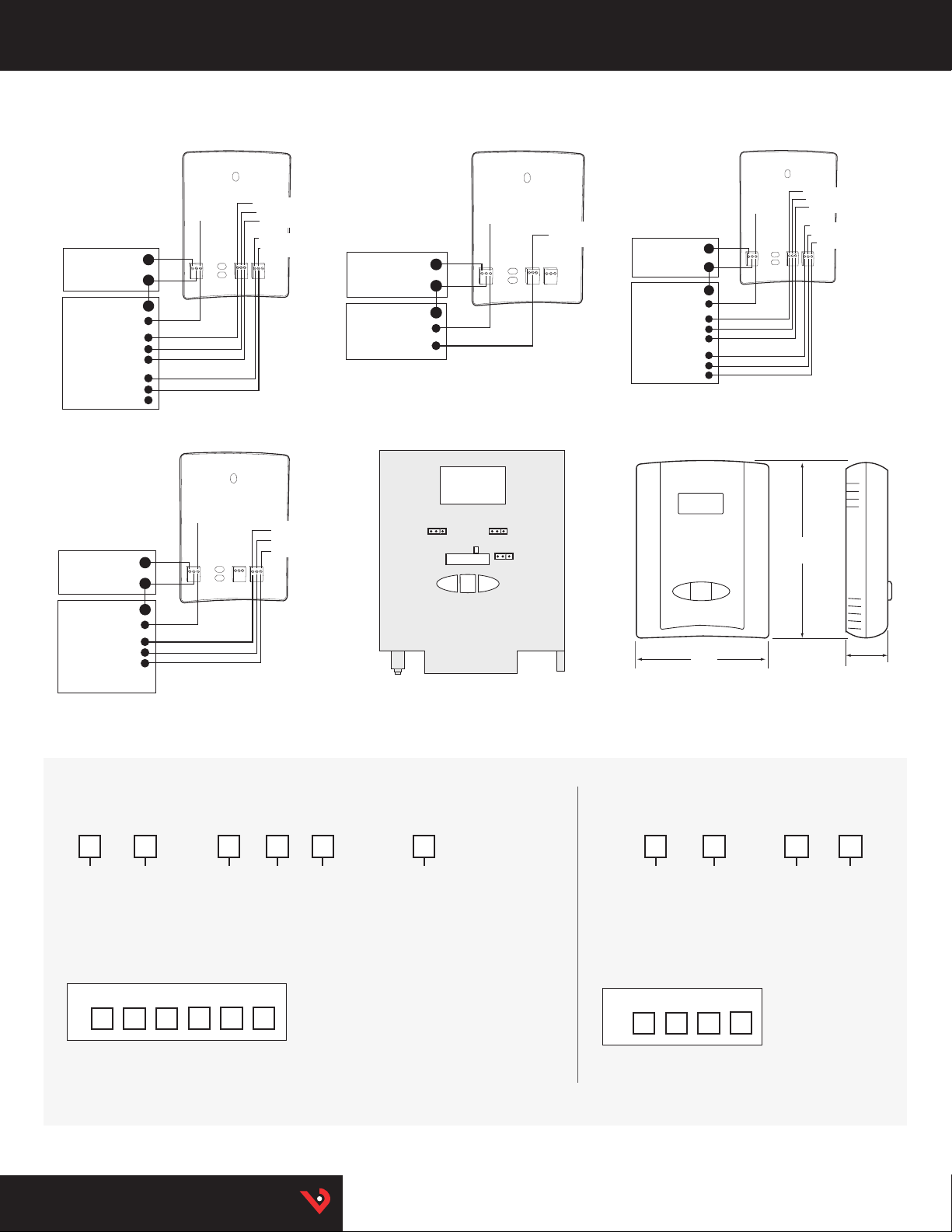
Setpoint Devices | HT/HWS Series
HT ANALOG OPTION
Wiring Examples
RH IN
Temp IN
+
GND
-
-
-
POWER SOURCE
15 to 30 Vdc or 24 Vac
DIGITAL CONTROL
RH setpoint IN
Temp setpoint IN
Thermistor/RTD IN
Thermistor/RTD IN
HWS RELAY OPTION
Wiring Examples
RH IN
Alarm Comm
+
GND
-
-
-
POWER SOURCE
15 to 30 Vdc or 24 Vac
DIGITAL CONTROL
Humidify Alarm
De-Humidify Alarm
RH output
RH output
Temp output
RH Setpoint output
Temp Setpoint output
Thermistor/RTD
Thermistor/RTD
Humidify Alarm
Alarm Comm
De-Humidify Alarm
HWS ANALOG OPTION
Wiring Examples
RH Output
RH Input
+
GND
-
-
-
POWER SOURCE
15 to 30 Vdc or 24 Vac
DIGITAL CONTROL
RH Setpoint Input
RH Setpoint Output
HT RELAY OPTION
Wiring Examples
RH output
RH IN
Temp IN
Comm Alarm
+
GND
-
-
-
POWER SOURCE
15 to 30 Vdc or 24 Vac
DIGITAL CONTROL
Thermistor/RTD IN
Thermistor/RTD IN
Heat/Humidify Alarm
Cool/De-Humidify Alarm
DIMENSIONAL DRAWINGCONFIGURATION
Enter
-+
3.5"
(89 mm)
Temp output
Thermistor/RTD
Thermistor/RTD
Heat/Hum. Alarm output
Comm Alarm output
4.75"
(121 mm)
Cool/De-Hum. Alarm output
1.2"
ORDERING INFORMATION
RH/T Combination Device
Accuracy
NIST
HT
1 = 1%
2 = 2%
3 = 3%
5 = 5%
Example:
HT Serie s devices contain bo th humidity and
tempera ture transmitt er outputs. Opt ional RTDs and
thermistors are available.
*Not avail able in W or Y high accur acy thermisto rs.
N2 R S 1 HHT
N = NIST
(1 & 2% only)
X =No
(2, 3, 5% only)
Setpoint
A = Analog
R = Relay
RH Only Device
Temp Cal
Certicate
Option
NIST
HWS
Example:
1 = 1%
2 = 2%
3 = 3%
5 = 5%
N2 R SHWS
N = NIST
(1 & 2% only)
X = No
(2, 3, 5% only)
0 = None
= CE = CE
1 = 1 point Cal Ce rt*
2 = 2 point Cal Ce rt*
B = 100R Platinu m, RTD
C = 1k Platinum, RT D
D = 10k T2, Ther mistor
E = 2.2k, T hermistor
F = 3k, The rmistor
G = 10k CPC Ther mistor
H = 10k T3, Ther mistor
J = 10k Dale, The rmistor
K = 10k with 11k shunt, Therm istor
M= 20k NTC , Thermistor
N = 1800 ohm TAC, Ther mistor
Q = 1uA/C, Lini temp
R = 10k US, Ther mistor
S = 10k 3A 221
T = 100k, Th ermistor
U = 20k “D”, Ther mistor
W = 10k T2 high acc uracy, Thermis tor
Y = 10k T3 high acc uracy, Thermist or
SetpointAccuracy
A = Analog
R = Relay
SS
HQ0001872.F 0117
TM
 Loading...