

Page 1
Installation Guide
Humidity
• This product is not intended for life or safety applications.
• Do not install this product in hazardous or classied locations.
• Read and understand the instructions before installing
this product.
• Turn off all power supplying equipment before working on it.
• The installer is responsible for conformance to all applicable codes.
No responsibility is assumed by Veris Industries for any consequences arising out of the
use of this material.
NOTICE
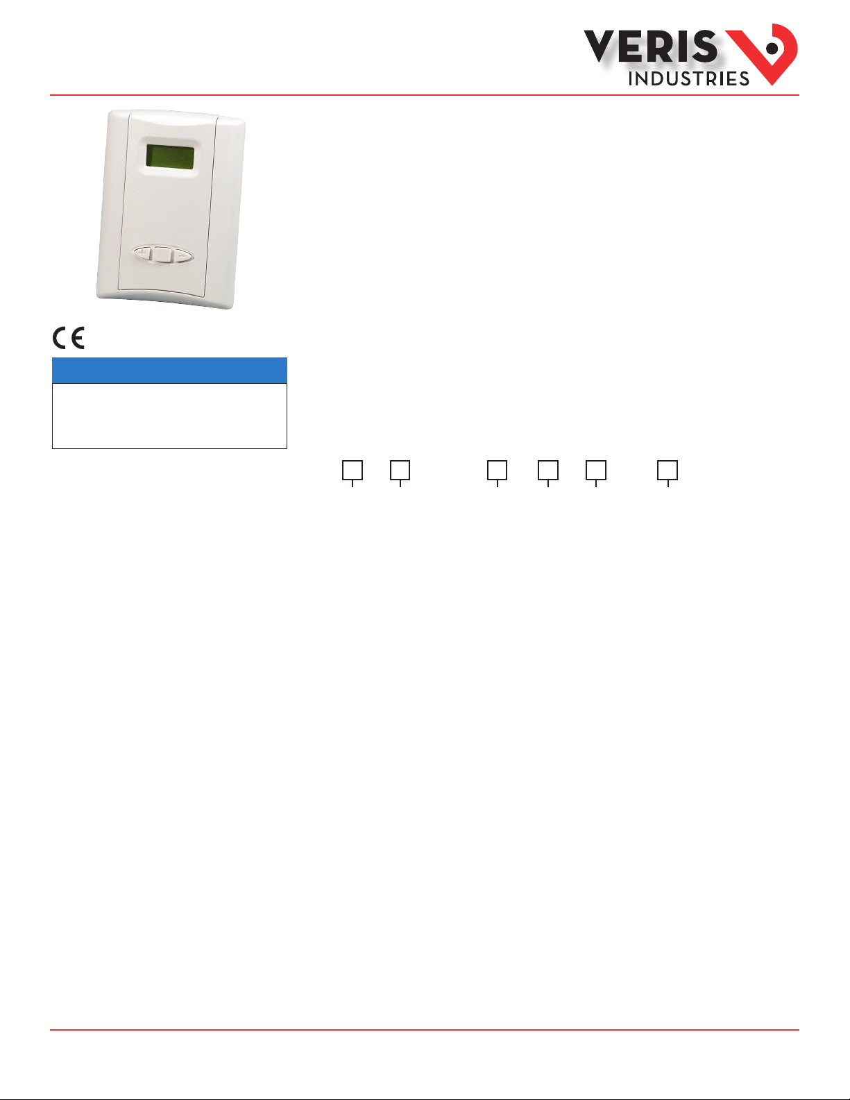
HT Series
Wall Mount with Analog Setpoints, LCD, and
Humidistat and Thermostat Control
Product Overview
The HT analog series has dual outputs to measure temperature and humidity of the air inside a room. Devices are
designed for use in hospital rooms, laboratories, and other spaces that require precise environmental control. The
keypad allows control of setpoint values. The slide switch position determines the output type (amp or volt). To
maintain accuracy, keep vents clear of dust, debris, etc. The HT is warranted for period of ve years.
Product Identification
Temp Cal
HT
2 = 2%
3 = 3%
5 = 5%
NIST
N = NIST (1 & 2% only)
X = No (2, 3, 5% only)
SetpointAccuracy
A
= Analog1 = 1%
S
= CE
Certificate
0 = None
1 = 1 point Cal
Validation
2 = 2 point Cal
Validation
Option
B = 100R Platinum, RTD
C = 1k Platinum, RTD
D = 10k T2, Thermistor
E = 2.2k, Thermistor
F = 3k, Thermistor
G = 10k CPC, Thermistor
H = 10k T3, Thermistor
I = 1k Balco (nickel-iron) RTD
J = 10k Dale, Thermistor
K = 10k w/11k shunt,Thermistor
M = 20k NTC, Thermistor
N = 1800 ohm TAC, Thermistor
Q = 1uA/C, Linitemp
R = 10k US, Thermistor
S = 10k 3A 221, Thermistor
T = 100k, Thermistor
U = 20k “D”, Thermistor
W = 10k T2 high accuracy, Thermistor
Y = 10k T3 high accuracy, Thermistor
Z = 10k E1, Thermistor
CC= 15k, Thermistor
TM
Z203269-0R Page 1 of 7 ©2014 Veris Industries 02141
Alta Labs, E nercept, Ensp ector, Hawkeye, Trus tat, Aerospo nd, Veris, and th e Veris ‘V’ log o are tradema rks or registe red tradema rks of Veris Ind ustries, L. L.C. in the USA and /or other countri es.
Other companies’ trademarks are hereby acknowledged to belong to their respective owners.
Page 2
Installation Guide
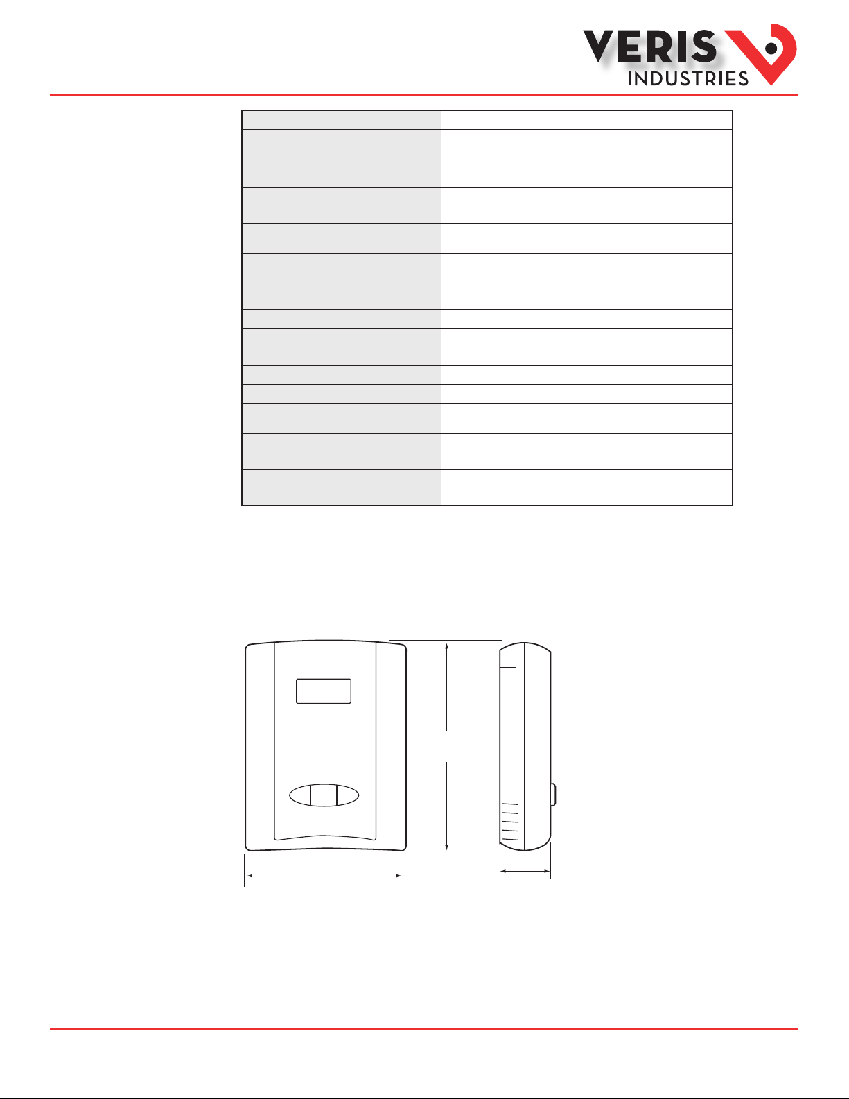
1.2"
(29 mm)
3.5"
(89 mm)
4.75"
(121 mm)
- +
Humidity
HTSeries
TM
Specifications
Input Power
Outputs
RH Sensor*
RH Accuracy at 25°C from 10-80% RH**
(Multi-point Calibration NIST traceable)
Reset Rate
Stability
Hysteresis
Linearity
Operating Humidity Range
Temperature Coefficient
Operating Temperature Range
Temperature Accuracy
Analog Output Scaling
Calibration Offset
Setpoint Range
15 to 30VDC/ 24VAC, 100mA max.
Switch-selectable amp or volt (switch affects both temp and
humidity outputs)
If volt is selected, the configuration menu allows selection
between 0 -5V or 0-10V
Digitally profiled thin-film capacitive (32-bit mathematics)
U.S. Patent 5,84 4,138
±2%, 3%, or 5% models, ±1% at 20 -50% RH
†
24 hours
±1% @ 20°C ( 68°F) annually, for two years
RH: 1.5% ( typical)
Included in Accurac y spec.
0-100% RH (non-condensing)
± 0.1%RH/ °C above or below 25°C (ty pical )
10° to 35°C (50° to 95° F)
± 1.0°C ( ± 1.8°F)
RH: 0-100% RH; Temp: 10° to 35°C (5 0° to 95°F) or 0 ° to 50° C
(32° to 122°F ) menu selec table
RH: Adjustable ±9.9% in 0.1% increments;
Temp: Adjustable ±9.9° ( C or F) in 0.1° increments
RH: 10 -8 0% RH in 1% increments;
Temp: Minimum to Full Scale in 1° increments
‡
Dimensions
* The HS sensing element has a 1-year warranty. The element is not a part of the 5-year product warranty.
** Accuracy is specified with 24 VDC supplied power with rising humidity.
†
Reset Rate is the time required to recover to 50% RH after exposure to 90% RH for 24 hours.
‡
If the 0° to 50°C (32° to 122°F) scaling range is selected, the device’s operating temperature range still applies.
One side of the transformer secondary is connected to the signal common, so an isolation transformer or
dedicated power supply may be required.
RTD/Thermistors in wall packages are not compensated for internal heating of the product.
EMC Special Note: Connect this product to a DC distribution network or an AC/DC power adaptor with proper
surge protection (EN 61000-6-1:2007 specification requirements).
Z203269-0R Page 2 of 7 ©2014 Veris Industries 02141
Alta Labs, E nercept, Ensp ector, Hawkeye, Trus tat, Aerospo nd, Veris, and th e Veris ‘V’ log o are tradema rks or registe red tradema rks of Veris Ind ustries, L. L.C. in the USA and /or other countri es.
Other companies’ trademarks are hereby acknowledged to belong to their respective owners.
Page 3
Installation Guide
Humidity
HTSeries
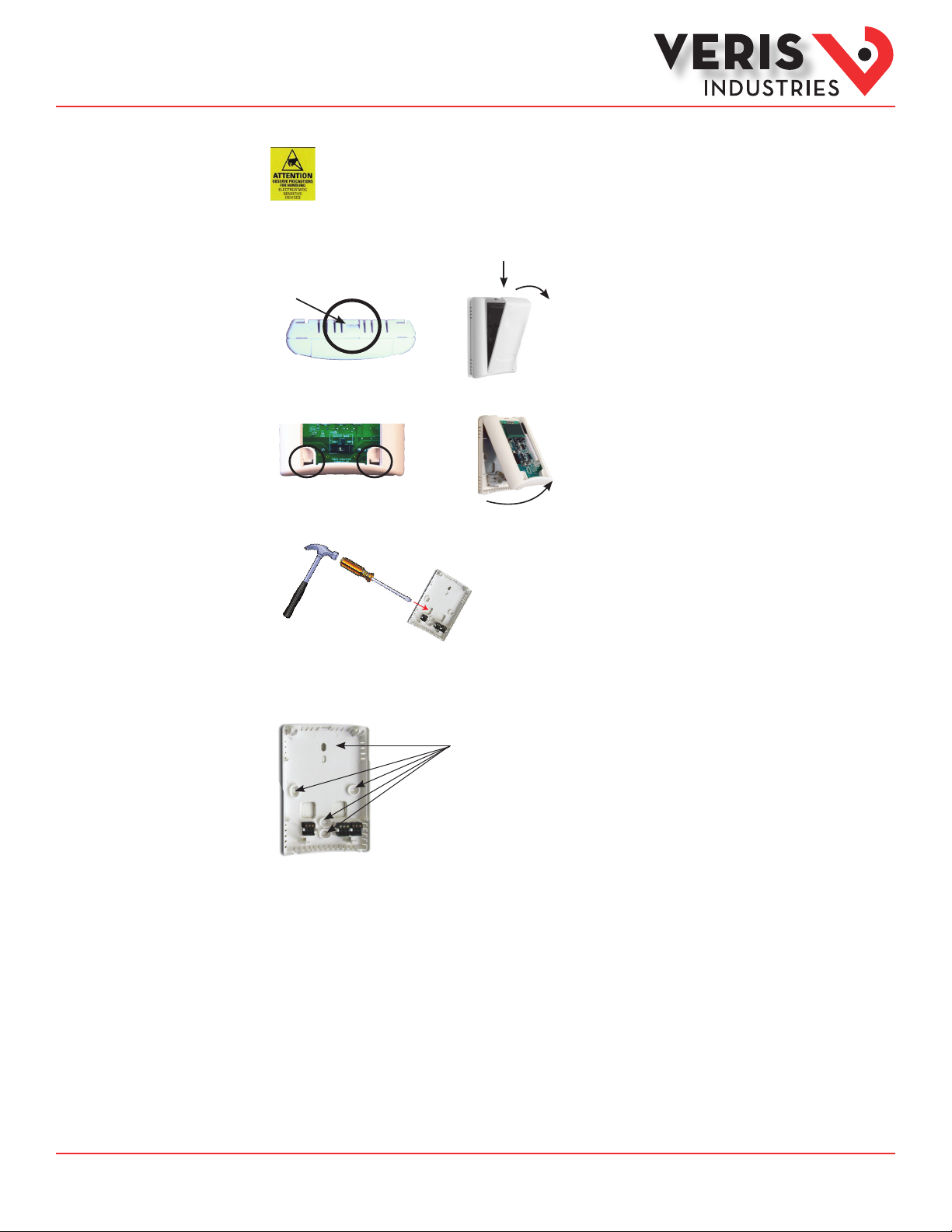
Installation
TM
Observe precautions for handling static sensitive
devices to avoid damage to the circuitry that
is not covered under the factory warranty.
1. Locate the tab at the top of the sensor housing. Using only the minimum required force, press this tab down and pull the cover
outward from the top. Set the cover aside.
Housing, Top View
Tab
2. Remove the backplate by unfastening the sensor from the bottom of the backplate and pivoting the sensor outward.
3. Punch out wire opening in the backplate.
4. Position the backplate vertically on the wall, 4 ½ feet (1.4 m) above the oor. Locate away from windows, vents, and other
sources of draft. If possible, do not mount on an external wall, as this might cause inaccurate temperature readings.
5. Mount the backplate onto the wall using the screws provided.
Five screwholes available; use a minimum
of two for secure mo unting.
Z203269-0R Page 3 of 7 ©2014 Veris Industries 02141
Alta Labs, E nercept, Ensp ector, Hawkeye, Trus tat, Aerospo nd, Veris, and th e Veris ‘V’ log o are tradema rks or registe red tradema rks of Veris Ind ustries, L. L.C. in the USA and /or other countri es.
Other companies’ trademarks are hereby acknowledged to belong to their respective owners.
Page 4

Installation Guide
RH
SENSOR
TEMP
SENSOR
RH
YES
AMP VOLT
NO YES
RUN
CAL
NO
TEMP
–
Minus Select Plus
+
Humidity
HTSeries
TM
Installation (cont.)
6. Wire the backplate.
RH Output
RH Input
+
GND
-
-
-
POWER SOURCE
15 to 30VDC or 24VAC
DIGITAL CONTROL
Temp Input
RH Setpoint Input
Temp Setpoint Input
Thermistor/RTD Input
Thermistor/RTD Input
7. Install and congure the sensor.
Temp Output
RH Setpoint Output
Temp Setpoint Output
Thermistor/RTD Output
Thermistor/RTD Output
RH YES/NO Jumper:
YES - allows user to change RH setpoi nt
NO - user can NOT change RH setpoint
NOTICE
RISK OF EQUIPMENT DAMAGE
Ensure that the output selection is correct before applying power.
Failure to follow these instructions may result in permanent
equipment damage.
8. When the installation is complete, replace the cover and snap it into position.
TEMP YES/NO Jumper:
YES - allows user to change temp setpoin t
NO - user can NOT change temp setpoint
RUN/CAL Jumper:
CAL Mode - allows ful l access to all features.
RUN Mode - allows access to relay setpoint s ONLY.
Z203269-0R Page 4 of 7 ©2014 Veris Industries 02141
Alta Labs, E nercept, Ensp ector, Hawkeye, Trus tat, Aerospo nd, Veris, and th e Veris ‘V’ log o are tradema rks or registe red tradema rks of Veris Ind ustries, L. L.C. in the USA and /or other countri es.
Other companies’ trademarks are hereby acknowledged to belong to their respective owners.
Page 5

Installation Guide
- +
Display screen
Scroll down
Select
Scroll up
7 0 F
Humidity
HTSeries
TM
Calibration
Instructions
Operation
Instructions
1. Temperature calibration allows for a calibration oset of ±9.9° (C or F), at the user’s discretion.
2. Relative humidity allows for a calibration oset of ±9.9% RH, at the user’s discretion.
RH and temperature can be eld calibrated by moving the RUN/CAL jumper to the CAL position.
Normal Operation
NORMAL MODE
4 5 . 5 % R H
6 8 . 5 º F
Temperature Selection
Use the (+) and (-) buttons to scroll to the Thermostat mode:
S E T P O I N T
Press +/- to change the setpoint value.
When the desired setpoint appears,
press the Select button to select.
The setpoint is in ˚C if Celsius units are selected.
Humidity Selection
Use the (+) and (-) buttons to scroll to the Humidistat mode:
S E T P O I N T
4 5 % R H
Press +/- to change the setpoint value.
When the desired setpoint appears,
press the Select button to select.
Z203269-0R Page 5 of 7 ©2014 Veris Industries 02141
Alta Labs, E nercept, Ensp ector, Hawkeye, Trus tat, Aerospo nd, Veris, and th e Veris ‘V’ log o are tradema rks or registe red tradema rks of Veris Ind ustries, L. L.C. in the USA and /or other countri es.
Other companies’ trademarks are hereby acknowledged to belong to their respective owners.
Page 6

Installation Guide
O U T P U T
0 - 1 0 V
U N I T S
* º F º C
Press +/- to change, press Select button to select.
Press +/- to change, press Select button to select.
Setpoint in ˚C if Celsius units are selected.
CONFIG/CAL MODE
(Enter by any keypress when
Run/Cal jumper is in CAL position)
4 5 . 5 % R H
6 8 . 5 º F
NORMAL MODE
Press +/- to change, press Select button to select.
Press +/- to change, press Select button to select.
Press +/- to change, press Select button to select.
Press +/- to change, press Select button to select.
Setpoint in ˚C if Celsius units are selected.
Press +/- to change, press Select button to select.
Options are 10˚ to 35˚C (50˚ to 95˚F) or 0˚ to 50˚C (32˚ to 122˚F).
S E T P O I N T
7 0 F
S E T P O I N T
4 5 % R H
C A L T
+ 0 . 0 F
C A L R H
+ 0 . 0 %
T E M P S E T
+ 5 0 + 9 5
Output Scaling
(does not aect LCD display)
Only if switch is in
Volts position
Humidity
HTSeries
Menu Options
TM
Z203269-0R Page 6 of 7 ©2014 Veris Industries 02141
Alta Labs, E nercept, Ensp ector, Hawkeye, Trus tat, Aerospo nd, Veris, and th e Veris ‘V’ log o are tradema rks or registe red tradema rks of Veris Ind ustries, L. L.C. in the USA and /or other countri es.
Other companies’ trademarks are hereby acknowledged to belong to their respective owners.
Page 7

Installation Guide
Humidity
HTSeries
TM
Replacing the
HSElement
Observe precautions for handling static sensitive
devices to avoid damage to the circuitry that
is not covered under the factory warranty.
1. Disconnect power to the unit.
2. Remove the faceplate.
3. Remove the HS element by gently pulling from the pin connector.
4. Place a new HS element onto the pin connector. Orient as shown, or the unit will not function. Ensure that the four HS pin holes
are inserted fully onto the unit pin connectors.
Top
Side
5. Replace the faceplate.
Bottom
Side
Z203269-0R Page 7 of 7 ©2014 Veris Industries 02141
Alta Labs, E nercept, Ensp ector, Hawkeye, Trus tat, Aerospo nd, Veris, and th e Veris ‘V’ log o are tradema rks or registe red tradema rks of Veris Ind ustries, L. L.C. in the USA and /or other countri es.
Other companies’ trademarks are hereby acknowledged to belong to their respective owners.
 Loading...