

Page 1
Humidity Monitoring | Deluxe Duct & Outdoor Humidity Sensors
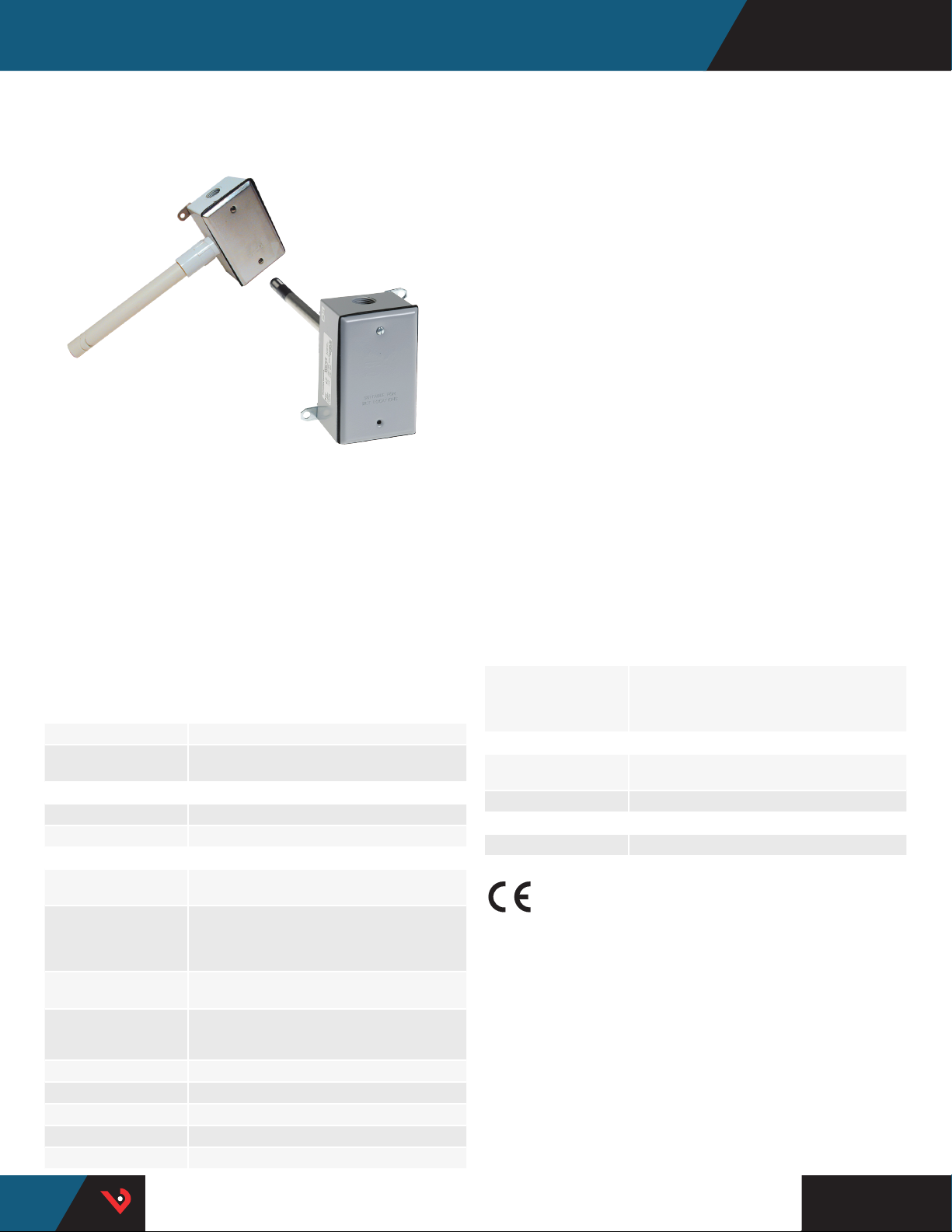
HD & HO SERIES
1% & 2% NIST, or Standard 2%, 3%, or 5%
HO
HD
HD and HO Series deluxe humidity transmitters provide an ideal
solution for measuring relative humidity in a wide range of conditions.
All devices are equipped with a thin-film capacitive sensor that is easily
replaceable in the field. These sensors are calibrated to NIST standards,
with certificates available (see Ordering Information; choose “N” in
NIST block). Temperature sensing options are also available. The duct
mounted HD is encased in a die cast metal housing for extra strength.
The outdoor HO housing is completely weather proof – the most rugged
sensor available. All deluxe HD and HO models come with a standard
five-year warranty.
SPECIFICATIONS
INPUT POWER
Voltage Model* Class 2; 12 to 30 Vdc/24 Vac, 15 mA max.
mA Model Class 2; Loop powered 12 to 30 Vdc only,
OUTPUT
Voltage Model 3-wire, observe polarity
mA Model 2-wire, not polarity sensitive (clipped and capped)
HUMIDITY
HS Element† Digitally profiled thin-film capacitive
Accuracy at 25°C from
10-80% RH**
(Multi-point calibration,
NIST traceable)
Temperature Effect, Duct
Model
Temperature Effect,
Outdoor Model
Scaling 0 to 100% RH
Hysteresis 1.5% typical
Linearity Included in accuracy spec.
Reset Rate*** 24 hours
Stability ±1%@20 °C (68 °F) annually, for two years
†
30 mA max.
(32-bit mathematics) U.S. Patent 5,844,138
HD only: ±1% at 20 to 40% RH in mA output mode;
(multi-point calibration, NIST traceable)
All models: 2%, 3%, or 5% (specify)
±0.1% RH/°C above or below 25 °C (typical)
4 to 20 mA version: (0.0013x%RHx(T°C-25));
0-5V/0-10V versions: (0.0015x%RHx(T°C-25))–
(%RHx0.0008xabs(T°C-25))
Sensor element
Thin-lm capacitive sensor
element recovers from
100% saturation
Accuracy
Fully interchangeable element to
1%, 2%, 3%, or 5%
Easy servicing
Duct sensor element can be
serviced without disturbing
conduit
Potted circuitry
Prevents costly condensate
shorts
accuracy…no calibration
Field replacable
Replace element in the eld…
maintain accuracy and minimize
downtime
Flexibility
Polarity insensitive, two-wire
4 to 20 mA or 3-wire 0-5/0-10
Vdc versions…exible systems
compatibity…save time in the
eld, stock fewer devices
APPLICATIONS
• Controlling HVAC systems for
improved comfort and energy
savings
• Museums, schools, printing
shops, and other locations
requiring humidity control
TEMPERATURE
Optional Temp.
Transmitter Output
HO Transmitter Accuracy
HD Transmitter Accuracy
OPERATING ENVIRONMENT
Operating Humidity
Range
Operating Temp. Range -40 to 50 °C (-40 to 122 °F)
WARRANTY
Limited Warranty 5 years †
AGENCY APPROVALS
† †
† All deluxe models come with a standard five -year warranty. The HS sensing element has a
1-year warrant y. The element is not a par t of the 5-year prod uct warranty.
†† The CE mark indicates RoHS2 compliance. Please refer to the CE Declaration of
Conformity for additional details.
* One side of transformer secondary is connected to signal common, so an Isolation
transformer or dedicated power supply may be required.
** Specified accuracy with 24 Vdc supplied power with rising humidit y. RTD/Thermistors
are not compensated for internal heating of product.
*** Rese t Rate is the time required to recover to 50% RH after exposure to 90% RH for 24
hours.
Shielded cabling is required for conformance to EMC standards. Technical information is
available from the fac tory upon request or from the Veris website at www.veris.com.
EMC Conform ance - CE Option: Low Voltage D irective 2014/35/EU and EMC Direc tive 2014/30/
EU.
EMC note: Conn ect this product t o a DC distribution ne twork or an AC/DC powe r adaptor with
proper surge protection (EN 61000-6-1 specification requireme nts).
Digital, 4 to 20 mA (clipped & capped) or
0-5/0-10 V output
±1.3 °C (±2.3 °F) typical;
±0.5 °C (1.0 °F) typical
0 to 100% RH non-condensing
• Facilitating compliance
with ASHRAE standards for
environmental control and
indoor air quality
TM
HQ0001790.H 0117
Page 2
Humidity Monitoring | HD & HO Series
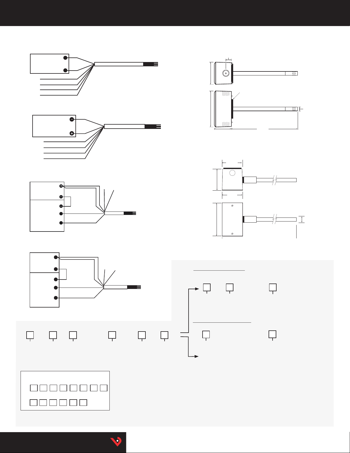
HD/HO 0-5V/0 -10V TEMPERATURE TRANSMITTER
VERSIONS
Wiring Diagram
BLK
–
POWER SUPPLY
24 Vdc
RED
+
BLUE 0 to 10 V HUMIDITY
ORANGE 0 to 10 V TEMP
GREEN 0 to 5 V HUMIDITY
YELLOW 0 to 5 V TEMP
HO 0-5V/0-10V RESISTANCE VERSIONS
Wiring Diagram
BLK (Common)
RED
optional
POWER SOURCE
AC/DC
(See Specifications)
BLUE 0 to 10 V HUMIDITY
GREEN 0 to 5 V HUMIDITY
ORANGE THERMISTOR
{
ORANGE THERMISTOR
HD/HO (4-20 mA TEMPERATURE TRANSMITTER VERSIONS)
Wiring Diagram
POWER SOURCE
DC Only
(See specifications)
DIGITAL CONTROL
4 to 20 mA Return
Temperature
4 to 20 mA Return
Humidity
(optional)
BLUE
HUMIDITY
ORANGE
TEMP
BLUE
HUMIDITY
ORANGE
TEMP
White/Gray 0 to 1 V
Test Leads for use
with voltmeter
HO (4-20 mA RESISTANCE VERSIONS)
Wiring Diagram
BLUE
HUMIDITY
ORANGE
TEMP
BLUE
HUMIDITY
ORANGE
TEMP
White/gray 0 to 1 V
test leads for use
with voltmeter
POWER SUPPLY
24 Vdc only
DIGITAL CONTROL
Humidity
4 to 20 mA Return
Temperature
4 to 20 mA Return
(optional)
+
–
–
ORDERING INFORMATION
Enclosure
H
D = RH Duct
O = Outdoo r
*1% not availabl e on HO.
** Not avai lable with W and Y high -accuracy th ermistors.
Examples
Tem p:
H
No Te mp:
H
Accuracy
1 = 1%*
2 = 2%
3 = 3%
5 = 5%
D 2 N V C T C 2
O 2 X M S X
NIST
N = NIST 1% & 2% only
X = None 2%, 3% ,
5% only
Output
M = 4 to 20 mA
V = 0-5V/0-10 Vdc
US or EU
S = Standard
C = CE
Tem p.
T = Temp
X = No Temp
(Stop he re)
HD
Dimensional Drawing
2.9"
(74 mm)
4.6"
(117 mm)
HO
Dimensional Drawing
2.3"
(58 mm)
4.6"
(116 mm)
Humidity Transmitter Combination
Sensor Type Range
A
= Tra nsmi tte r
Humidity RTD/Thermistor Combination
Sensor Type
B = 100R Platinu m, RTD
C = 1k Platinum, RT D
D = 10k T2, Ther mistor
E = 2.2k, T hermistor
F = 3k, The rmistor
G = 10k CPC, The rmistor
H = 10k T3, Ther mistor
J = 10k Dale, The rmistor
K = 10k with 11k shunt, Therm istor
M = 20k NTC, T hermistor
N = 1800 ohm TAC, Ther mistor
Q = 1uA/˚C, Li nitemp
R = 10k US, Ther mistor
S = 10k 3A 221, Thermisto r
T = 100k, Th ermistor
U = 20k “D”, Ther mistor
W = 10k T2 high acc uracy, Thermis tor
Y = 10k T3 high acc uracy, Thermist or
0.7"
(18 mm)
2.0"
(51 mm)
2.7"
(69 mm)
2.8"
(72 mm)
1 = -40 to 50 ° C
(-40 to 122 °F)
2 = 0 to 50 °C
(32 to 122 °F)
Foam Gasket
2.5" x 2.5"
(64 mm x 64 mm)
8.5"
(216 mm)
OPTION Temp. Cert
Blank = Non e
1 =1pt cal
2 = 2pt cal
OPTIO N Temp. Cer t
Blank = Non e
1 = 1pt cal**
2 = 2pt cal**
0.5" Dia.
(13 mm.)
0.7"
(18 mm)
HQ0001790.H 0117
TM
 Loading...