

Page 1
TM
HAZARD OF ELECTRIC SHOCK, EXPLOSION, OR ARC FLASH
• Follow safe electrical work practices.
See NFPA 70E in the USA, or applicable local codes.
• This equipment must only be installed and serviced by qualified electrical personnel.
• Read, understand and follow the instructions before installing this product.
• Turn off all power supplying equipment before working on or inside the equipment.
• Use a properly rated voltage sensing device to confirm power is off.
DO NOT DEPEND ON THIS PRODUCT FOR VOLTAGE INDICATION
• Only install this product on insulated conductors.
Failure to follow these instructions will result in death or serious injury.
DANGER
CURRENT MONITORING
INSTALLATION GUIDE
H740
TM
740
Installer’s Specifications
Sensor Power Induced from monitored conductor
Amperage Range 0.5 to 200 A continuo us
Insulation Class 600 VAC RMS
Frequency Range 50/60 Hz
Temperature Rang e -15° to 60°C (5° t o 140°F)
Humidity Range 10-90% RH non-condensing
Relay Coil 24 VAC/DC; 10 mA
Relay Contac t 8(3.5) A@250 VAC/DC, 30 VDC, 1/4 HP
Status Output N.O. 1.0 A@30 VAC/DC
O-S tate Resistance 0 (open switch represents >1 MΩ)
Terminal Block Max. Wire Size 14 AWG
Terminal Block Torque (nom.) 4 in-lbs (0.45 N-m)
Agency Approvals UL508 E150462
The product design provi des for basic insulation only.
installation
Disconnect and lock out power to the enclosure containing the
conductor to be monitored.
1. Locate a mounting surface for the removable mounting bracket that will allow
the monitored conductor to pass through the center window when it is installed
and that will keep the device at least 1/2” from any uninsulated conductors.
Determine cable routing for the controller connection, allowing wiring to reach
the mounting location.
2. Drill holes to mount the bracket to the chosen surface using the included screws.
NOTICE
3. Wire the output connections and relay between the sensor and the controller
• This product is not intended for life or safety applications.
• Do not install this product in hazardous or classified locations.
• The installer is responsible for conformance to all applicable codes.
• Mount this product inside a suitable fire and electrical enclosure.
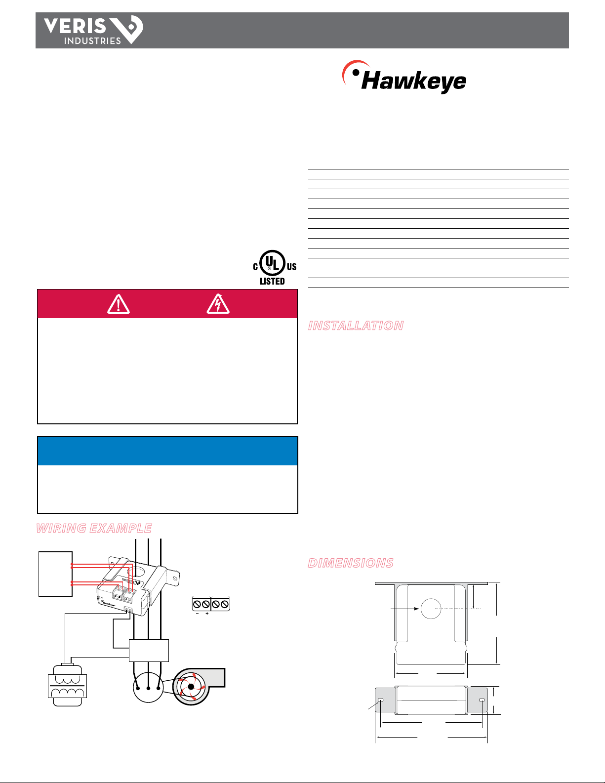
Wiring ExamplE
Digital Control
DI
(Status)
DO
(Relay
Coil)
Find Quality Products Online at: sales@GlobalTestSupply.com
24VAC/DC
RELAY COIL
STATUS
OUTPUT
1.0A@30 VAC/DC
730
CONTACTOR
Control
Power
Motor
RELAY COIL
Fan or Pump
* Observe this polarity
when connecting the
relay coil to DC Voltage.
www.GlobalTestSupply.com
(solid-state contact).
4. Wire sensor to control power.
5. Route the conductor through the sensor’s center window and slip the assembly
into the mounting bracket.
6. Secure enclosure and reconnect power.
DimEnsions
Removable/Adjustable Mounting Bracket
0.9"
(23 mm)
3.0"
(75 mm)
1.1"
(27 mm)
0.2” x 0.15”
slot (2x)
0.7"
(19 mm)
2.8"
(68 mm)
(95 mm)
4.2"
(106 mm)
3.8"
Page 2

TM
H74 0
INSTALLATION GUIDE
opEration
The H740 is a current-sensitive transducer that monitors current (amperage) in the
conductor passing through it. The integrated relay provides On/O control. The status
output is suitable for connection to building controllers or other appropriate data
acquisition equipment operating at up to 30 volts. The H740 requires no ex ternal
power supply to generate its output.
notEs
For load currents greater than sensor maximum rating:
Use a 5 Amp (H68xx series) Current Transformer (CT) as shown. This technique can be
combined with wrapping (see below) to add range for a low current load on a high
current source.
240A
> 200 A (Sensor max.)
5A
300A:
H68xx-5A CT
troublEshooting
Problem Solution
No Reading at Controller • Check for control power at sensor (<30 V; <1.0 A)
• Check for amperage in monitored conductor (>0.5 A)
Relay chatters or will not
change state
• Ensure that not more than 24 VAC/DC has been applied to
the coil.
• Parallel applications with AC transformers can damage the
relay. Use appropriate snubbing device.
DANGER: 5A CTs can present hazardous voltages.
Install CTs in accordance with manufacturer's instructions.
Terminate the CT secondary before applying current.
CAUTION
RISK OF EQUIPMENT DAMAGE
• Derate the product’s maximum current for the number of turns
through the sensing window using the following formula.
Rated Max. Amps ÷ Number of Turns = Max. monitored Amps
e.g. : 100A ÷ 4 Turns = 25 Amps max. in monitored conductor
• Failure to follow these instructions can result in overheating
and permanent equipment damage.
For load currents less than sensor minimum rating:
Wrap the monitored conductor through the center window and around the sensor
body to produce multiple turns. This increases the current measured by the
transducer.
< 0.5 A (Sensor Min.)
0.2 A
0.5A
4x
Find Quality Products Online at: sales@GlobalTestSupply.com
www.GlobalTestSupply.com
 Loading...