

Page 1
Installation Guide
Power Metering CTs
E207042
DANGER
HAZARD OF ELECTRIC SHOCK, EXPLOSION, OR ARC FLASH
• Follow safe electrical work practices. See NFPA 70E in the USA, or applicable local codes.
• This equipment must only be installed and serviced by qualified electrical personnel.
• Read, understand and follow the instructions before installing this product.
• Turn off all power supplying equipment before working on or inside the equipment.
• Product may use multiple voltage/power sources. Disconnect ALL sources before
servicing.
• Use a properly rated voltage sensing device to confirm that power is off.
DO NOT DEPEND ON THIS PRODUCT FOR VOLTAGE INDICATION.
• Current transformer secondaries must be shorted or connected to a burden at all times.
• Products rated only for basic insulation must be installed on insulated conductors.
• Replace all doors, covers and protective devices before powering the equipment.
Failure to follow these instructions will result in death or serious injury.
A qualied person is one who has skills and knowledge related to the construction and
operation of this electrical equipment and installations, and has received safety
training to recognize and avoid the hazards involved. NEC Article 100
If this product is used in a manner not specied by the manufacturer, the protection
provided by the product may be impaired. No responsibility is assumed by the
NOTICE
• This product is not intended for life or safety applications.
• Do not install this product in hazardous or classied locations.
• The installer is responsible for conformance to all applicable codes.
• Mount this product inside a suitable re and electrical enclosure.
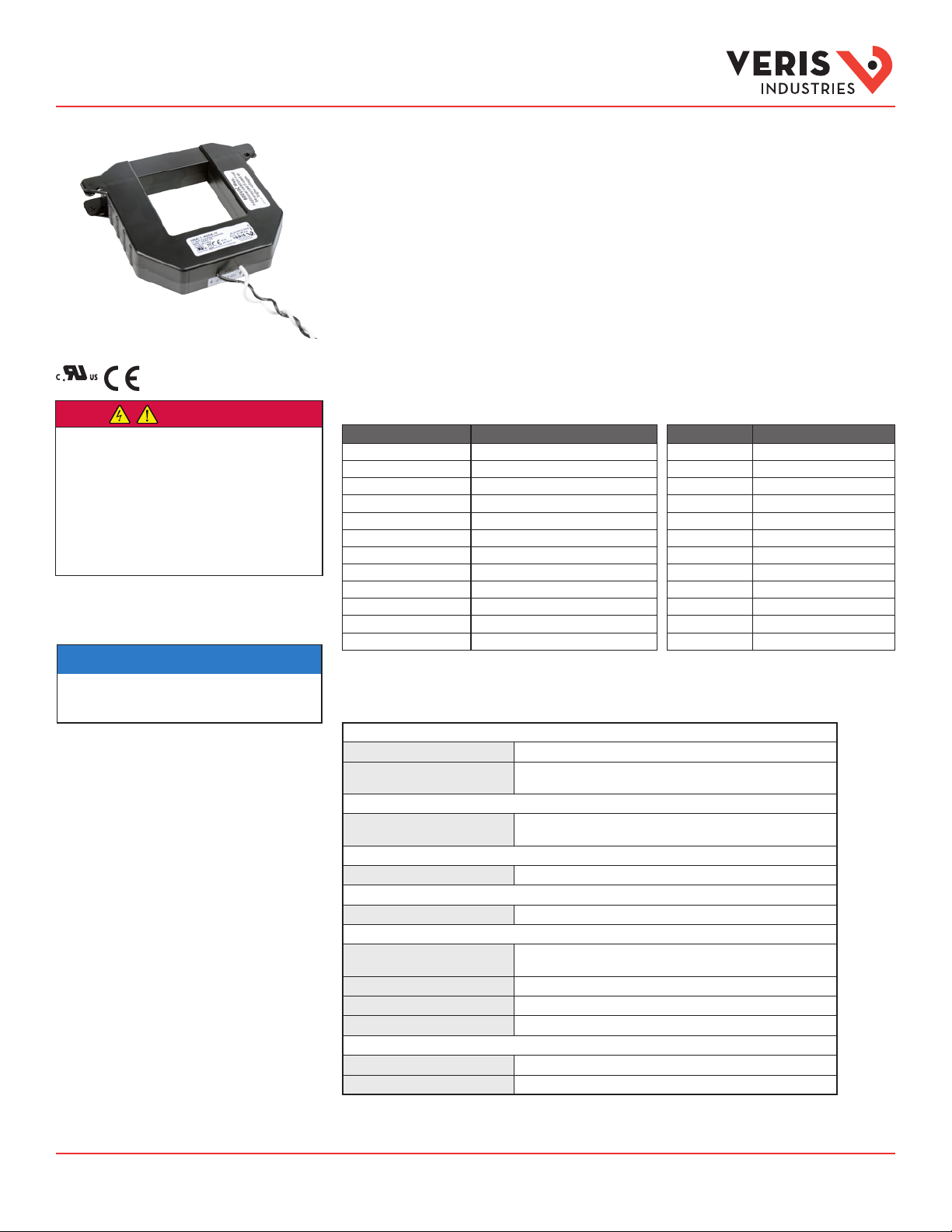
H681x-V Series
Split-Core Current Transformers, Voltage Output
Product Overview
The H681x-V series of 1 volt and 0.333 volt split-core current transducers (CTs) provide secondary AC voltage
proportional to the primary (sensed) current. For use with power meters, data loggers, chart recorders, and other
instruments, the H681x-V series CTs provide a cost-effective means to transform electrical service amperages to a
voltage compatible with monitoring equipment.
Product Identification
0.333 V Models* Description
H6810-100A-.3V (R20) Split-Core CT, Small, 100A:0.333V
H6810-200A-.3V (R20) Split-Core CT, Small, 200A:0.333V
H6810-300A-.3V (R20) Split-Core CT, Small, 300A:0.333V
H6811-400A-.3V (R20) Split-Core CT, Medium, 400A:0.333V
H6811-600A-.3V (R20) Split-Core CT, Medium, 600A:0.333V
H6811-800A-.3V (R20) Split-Core CT, Medium, 800A:0.333V
H6812-800A-.3V (R20) Split-Core CT, Large, 800A:0.333V
H6812-1000A-.3V (R20) Split-Core CT, Large, 1000A:0.333V
H6812-1200A-.3V (R20) Split-Core CT, Large, 1200A:0.333V
H6812-1600A-.3V (R20) Split-Core CT, Large, 1600A:0.333V
H6812-2000A-.3V (R20) Split-Core CT, Large, 2000A:0.333V
H6812-2400A-.3V (R20) Split-Core CT, Large, 2400A:0.333V
*Models endin g with R20 have 20 ft (6 m) leads. Example: H6810-100A-.3VR20.
Specifications
INPUTS
Frequency Range 50/60 Hz
Leads 6 ft (1.8 m)
20 ft (6 m)
ACCURACY
Accuracy ±1% of reading from 10% to 100% of rated c urrent , specified with
the pri mary c onductor(s) cente red in the C T window.
OUTPUTS
Output at Rated Current 1 V or 0.333 V
MECHANICAL
Insulation 6 00 Vac
ENVIRONMENTAL
Operating Temp Range 240 0 A models only: -15 to 50 °C (5 to 122 °F);
All oth er models: -15 to 60 °C (5 to 140 °F)
Storage Temp Range - 40 to 70 °C (-40 t o 158 °F)
Humidity Range 0 to 95% non-condensing
Altitude of Operation 3 km max.
COMPLIANCE INFORMATION
Agency Approvals UL 61010 -1, EN 61010 -1
Installation Category Category III, Pollu tion Degree 2
1 V Models Description
H6810-100A-1V Split-Core CT, Small, 100A:1V
H6810-200A-1V Split-Core CT, Small, 200A:1V
H6810-300A-1V Split-Core CT, Small, 300A:1V
H6811-400A-1V Split-Core CT, Medium, 400A:1V
H6811-600A-1V Split-Core CT, Medium, 600A:1V
H6811-800A-1V Split-Core CT, Medium, 800A:1V
H6812-800A-1V Split-Core CT, Large, 800A:1V
H6812-1000A-1V Split-Core CT, Large, 1000A:1V
H6812-1200A-1V Split-Core CT, Large, 1200A:1V
H6812-1600A-1V Split-Core CT, Large, 1600A:1V
H6812-2000A-1V Split-Core CT, Large, 2000A:1V
H6812-2400A-1V Split-Core CT, Large, 2400A:1V
TM
Z202815- 0K Page 1 of 2 ©2016 Veris Industries 0316
Alta Labs, E nercept, Ensp ector, Hawkeye, Tru stat, Aerospo nd, Veris, and th e Veris ‘V’ log o are tradema rks or registe red tradema rks of Veris Ind ustries, L. L.C. in the USA and /or other countri es.
Other companies’ trademarks are hereby acknowledged to belong to their respective owners.
Page 2
Hx-VSeries Installation Guide
TM
A
B
E
F
C
D
B
E
F
C
D
A
A
B
E
C
F
D
Wire t
i
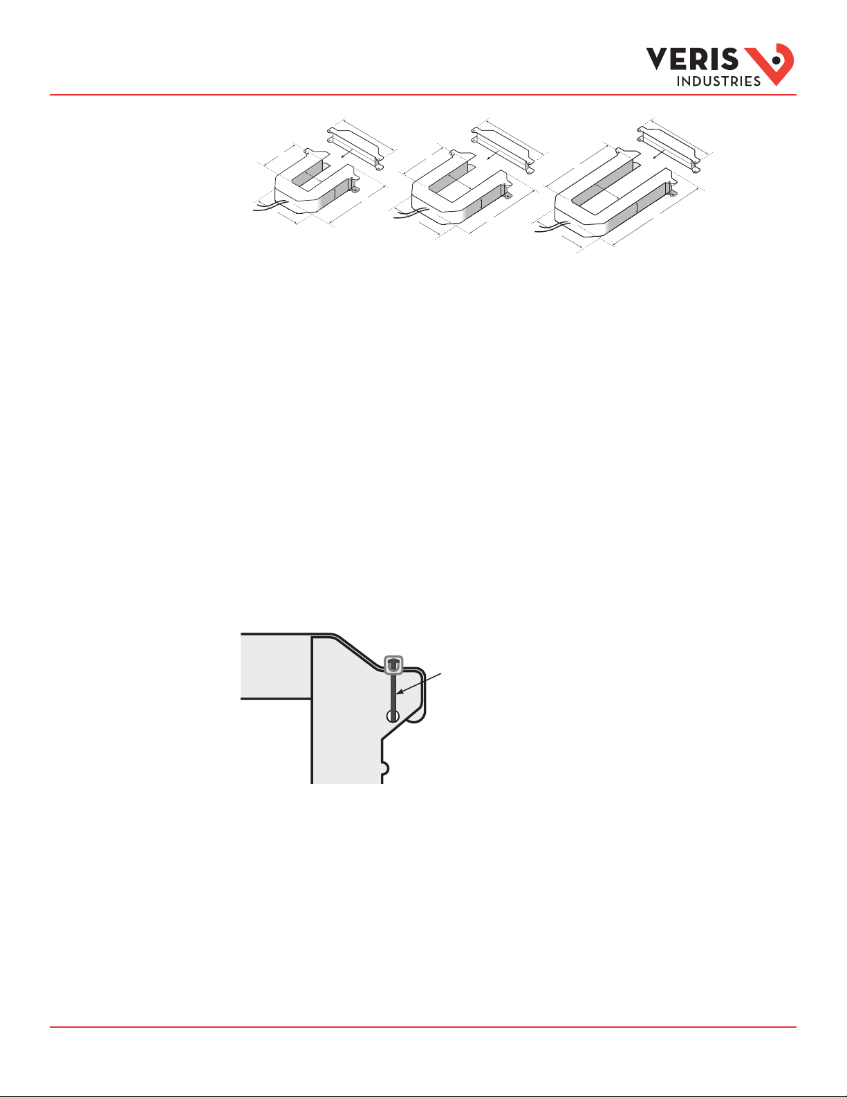
Dimensions
Installation
H6810/Small
100 Amp, 200 Amp, 300 Amp
H6811/Medium
400 Amp, 600 Amp, 800 Amp
H6812/Large
800 Amp, 1000 Amp, 1200 Amp,
1600 Amp, 2000 Amp, 2400 Amp
A = 3.8” (96 mm)
B = 1.2” (30 mm)
C = 1.3” (32 mm)
D = 1.2” (30 mm)
E = 4.0" (100 mm)
F = 4.8" (121 mm)
A = 4.9” (125 mm)
B = 2.9” (73 mm)
C = 2.5” (62 mm)
D = 1.2" (30 mm)
E = 5.2” (132 mm)
F = 6.0" (151 mm)
A = 4.9” (125 mm)
B = 5.5” (139 mm)
C = 2.5” (62 mm)
D = 1.2” (30 mm)
E = 7.9" (201 mm)
F = 6.0" (151 mm)
1. Disconnect and lock out power to the primar y circuit before installing these CTs.
2. Connect the secondary leads to the burden or test switching/shorting bar. The white wire is the X1 lead.
3. Depress the tabs on one end of the CT to open it. Check the core ends on both sections of the CT to ensure there is no rust or
debris in the closure areas.
4. Slip the CT over the primary leads. Note labeling on the product indicating “source side.”
5. Close and latch the CT, and mount it securely.
6. In any application where fault currents can exceed 20 times rated current of CT, use wire ties or similar fasteners to secure the
I-bar to the CT housing (see below). Secure both sides of the I-bar.
Secure the I-ba r with a wire tie in
applicatio ns where a fault current
could exceed 20x rated cu rrent.
7. Reconnect power to the panel.
An optional m ounting kit is available for t hese devices (Veris part number AH 06).
Ratings
These products provide basic insulation to 600 Vac between the sensed conductor and the output leads. For reinforced
applications, the installer must provide appropriate insulation. Reinforced insulation is provided for applications to 300 Vac
between the sensed conductor and the output leads.
Z202815- 0K Page 2 of 2 ©2016 Veris Industries 0316
Alta Labs, E nercept, Ensp ector, Hawkeye, Tru stat, Aerospo nd, Veris, and th e Veris ‘V’ log o are tradema rks or registe red tradema rks of Veris Ind ustries, L. L.C. in the USA and /or other countri es.
Other companies’ trademarks are hereby acknowledged to belong to their respective owners.
 Loading...