

Page 1
WARNINGS
DANGER OF ELECTROCUTION: BE CERTAIN THAT EVERY
CT IS CONNECTED TO A LOAD AT ALL TIMES WHEN CLAMPED TO AN ENERGIZED
CONDUCTOR. Current mode Current Transformers (CTs) such as those used
in this produc t can be damaged, or generate lethal voltages, if clamped
around current carrying conductors while the output leads are not properly terminated to a shorting device, or loaded, as by the H663SM main
board. Install wiring connec tors in accordance with manufacturer's specifica-
tions and instructions.
• Potential elec trocution hazard exists. Installing sensors in an energized
electrical panel, or on any energized conductor can be ha zardous. CT
outputs should not be connected to Operator Accessible circuits.
• Read instructions thoroughly prior to install
• This product is not intended for life or safety applications.
• This product is not intended for installation in hazardous or classified
locations and must be installed in an electrical and fire enclosure in accordance
with EN 61010-1.
Severe injury or death can result from electrical shock during contact with high
voltage conductors or related equipment. Disconnect and lock-out all power
sources during installation and service. Applications shown are suggested means
of installing sensors, but it is the responsibility of the installer to ensure that the
installation is safe and in compliance with all national and local codes. Installation should be attempted only by individuals familiar with codes, standards,
and proper safety procedures for high-voltage installations.
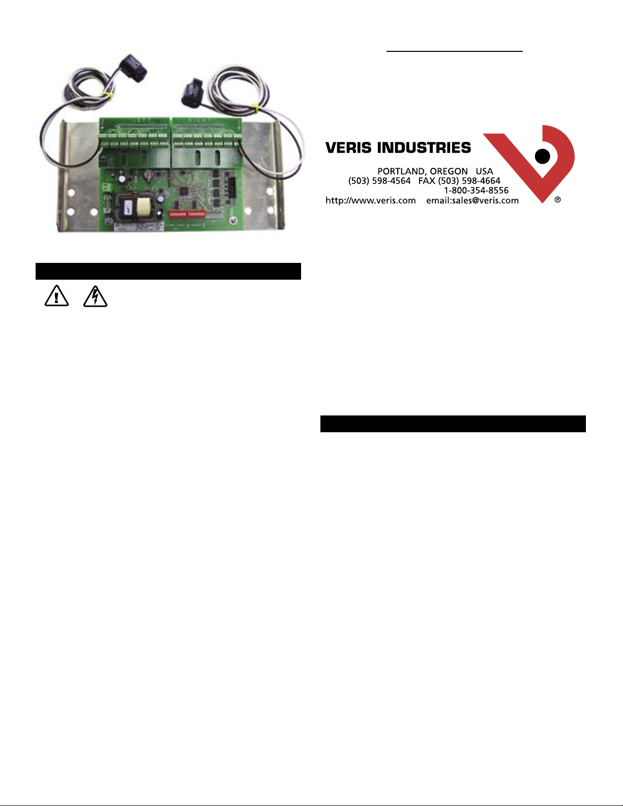
Installation Instructions
H663 Series
Split-Core Branch
Current Monitor
Easy Installation
■ First split-core solution for branch current monitoring in the indus try!
■ Monitor up to 42 (breakers) poles wi th one product
■ Split-core C T’s provide quick and easy installation...ideal for retrofi t
■ Simple two wire 120 VAC power connection*
Network Ready RS485 Output
■ Retrieve amperage information from up to 42 circuits with one R S485 drop...
easy wiring
■ Global alarm r egister for instant alarm and warning notification
■ Integrates to available network display for local indication
■ Easy to use configuration soft ware simplifies setup and provides flexibilit y to customize
the configuration to meet the application
OPERATION
Designed for the critical load monitoring such as Co-location Data Centers and
lighting panels, the H663 series monitors current on up to 42 branch circuits in
a 120/208/240 VAC electrical panel. By individually reporting current draw and
initiating capacity warnings and alarms, the H663 series allows the user to manage
loading and eliminate power disturbances caused by overloaded breakers.
The H663 series consists of a data acquisition system board and up to 42 individual
split-core current transformers (CTs). The acquisition board should be mounted inside the electrical panel, or in an enclosure mounted near enough for the CT output
leads to reach the acquisition board connectors. The CTs are clipped onto each of the
branch circuit conductors. These CTs transmit amperage data from each monitored
circuit to the acquisition system for processing.
Current and alarm information is transmitted to the user’s Control Data Acquisition
system over an RS485 drop using the Modbus protocol.
Set-up is made easy with a PC based configuration tool which allows for global or
individual selection of breaker size, warning levels, and alarm levels.
The H663 Series is a UL508 Listed open device without enclosure.
*For 240VAC Power connection versions, order catalog number H663SM-xxE
Z202833-0K ©2006 Veris Indus tries 10061
Shop for Power Metering products online at:
www.PowerMeterStore.ca
-1-
1.877.766.5412
Page 2
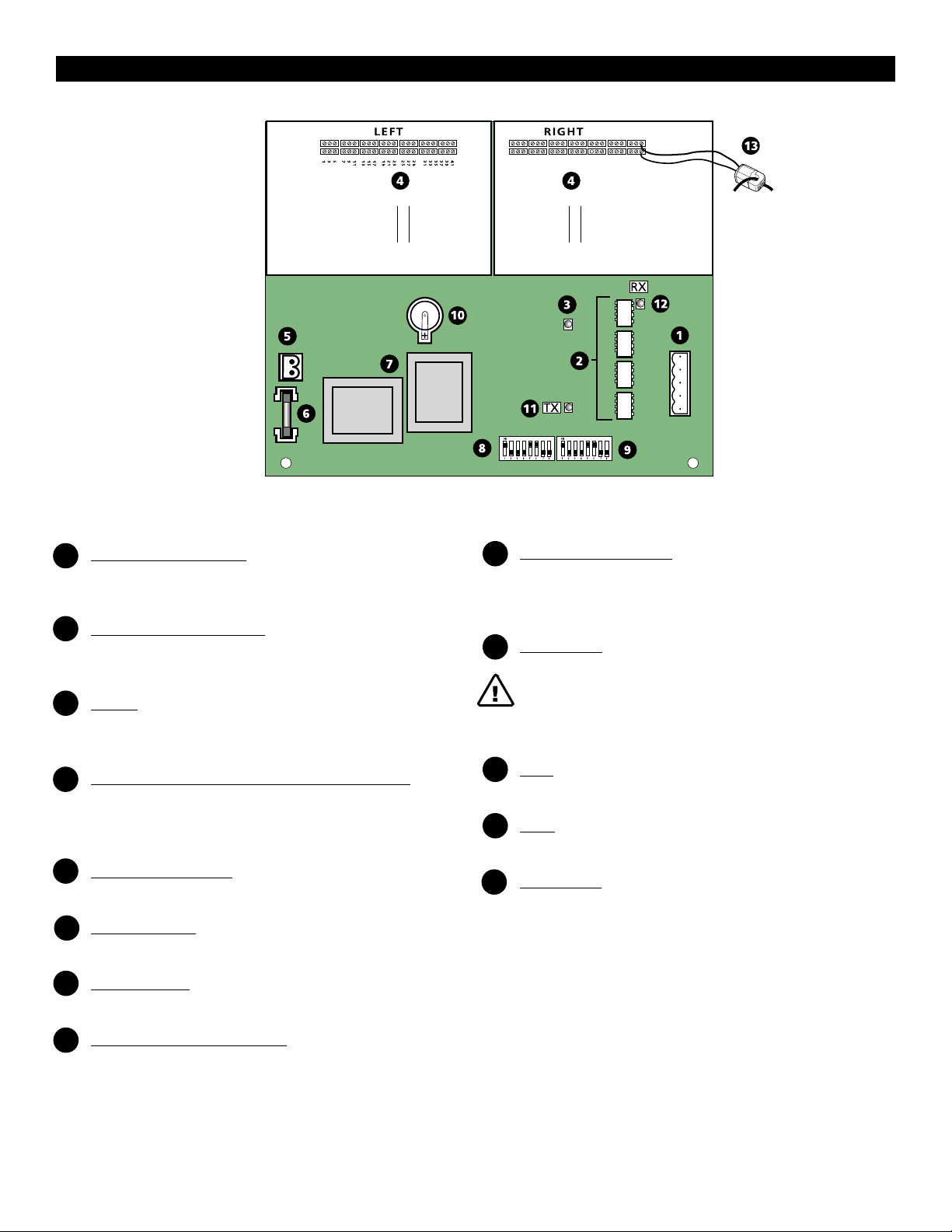
INSTALLATION
64212108181614242220302826363432424038
Figure 1
1 RS 485 2 or 4-Wire Connection
Daisy chain multiple H663's using a 2-wire or 4-wire modbus network. Refer
to Figure 4 on page 7.
2 Optical Communications Isolation
Optical isolators are used to separate 120 VAC portions of the circuit from the
RS485 network.
3 Alive LED
Flashes once per second to indicate correc t operation. If steadily lit or out,
indicates internal failure.
4 Current Transformer (CT) Connectors (Interconnection Boards)
Numbered terminals correspond to the input channels of the acquisition
board. Fasten the current transformer connectors into the terminals as
shown in figure 3 on page 3.
5 120 VAC Power Connection*
Easy 2-wire 120 VAC line to neutral 50/60 Hz.
6 250 VAC 100mA Fuse
Fused power connection for circuit protection.
7 Power Transformer
Linear power supply for reliability and low noise
9 Modbus Address Dip Switches
Each Modbus device must have a unique address. These switches must be set
to assign an individual address before the device is connected to the
network. (See page 5)
10 Lithium Battery
CAUTION! DANGER OF EXPLOSION IF BATTERY IS INCORRECTLY
REPLACED. REPLACE ONLY WITH THE SAME OR EQUIVALENT
TYPE RECOMMENDED BY THE MANUFACTURER. DISPOSE OF
USED BATTERIES ACCORDING TO THE MANUFACTURER'S
INSTRUCTIONS.
11 TX LED
Indicates transmission of information over the Modbus network.
12 RX LED
Indicates data received on the Modbus network
13 Current Sensors
Each current sensor is capable of monitoring conductors carrying up to a
maximum of 50 amps.*
* The H663SM-42H is capable of monitoring conductors up to a maximum of 100 amps.
8 Baud Rate & Parity Selection Switches
Field selectable RS-485 serial interface control.
(See Chart 1 on page 5)
*For 240VAC Power Connection versio n, order catalog number H663SM-xxE.
Z202833-0K ©2006 Veris Indus tries 10061
Shop for Power Metering products online at:
www.PowerMeterStore.ca
-2--2-
1.877.766.5412
Page 3

INSTALLATION
Panel Board 1
20
20
20
20
20
20
20
20
20
20
20
20
20
20
20
20
20
20
20
20
20
20
20
20
20
20
20
20
20
20
20
20
20
20
20
20
20
20
20
20
LEFT RIGHT
4139373533312927252321191715131197531
42403836343230282624222018161412108642
Channel 4
Channel 2
Channel 3
Channel 41
Channel 1
"
"
"
"
"
"
"
"
"
"
Channel 42
"
"
"
"
"
"
"
"
"
"
64212108181614242220302826363432424038
L EF T R IG HT
Velcro Strap
holds cable
wire in plac
e
Branch circuit wir
e
6' Lead
64212108181614242220302826363432424038
Physical Installation
1. Snap split-core CT’s on branch circuit wires. (CT’s may need to be staggered).
2. Prepare 120VAC* 50/60Hz power leads and connect to line and neutral
terminals of the acquisition board. Allow wiring length to fit when board is
installed. DO NOT CONNECT LINE VOLTAGE UNTIL LAST STEP!
3. Connect current transformers to interconnection board terminals as shown in
Figure 3.
4. Acquisition Board Installation (see Figure 2)
Find screw holes under panel board in side of chassis or panel. Attach
Data Acquisition Board.
Figure 2
DANGER: Beware of exposed busbars on back o f panelboard when installing circuit boa rd
assembly/mounting bracket. Assure adeq uate clearance between live parts and this prod uct.
*240VAC for H663SM-xxE
Figure 3
Z202833-0K ©2006 Veris Indus tries 10061
Shop for Power Metering products online at:
www.PowerMeterStore.ca
-3--3-
1.877.766.5412
Page 4

INSTALLATION
Data Acquisition Board
11.375"
(289 mm)
1.12"
(28 mm)
5.75"
(146 mm)
Data Acquisition Board
Mounting Bracket Kit
Acquisition and interconnection boards are mounted to the bracket at the factory.
Z202833-0K ©2006 Veris Indus tries 10061
Shop for Power Metering products online at:
-4-
www.PowerMeterStore.ca
1.877.766.5412
Page 5

1
1 2 4 8 16 32 64 128
O
N
1
CONFIGURATION
1
X
X
X
X
X
X
2
On
Off
3
Off
On
Off
On
4
Off
Off
On
On
5 6 7
X
X
X
X
X
X
8
X
X
X
X
X
X
2400 Baud
4800 Baud
9600 Baud
19200 Baud
2 wire
4 wire
Wiring, Baud Rate, Parity
Wi
ring
None
Ev
en
Od
d
Off
Off
On
Off
On
Off
ParityBaud Rate
DESIRED RESULT
Switch #
Baud Rate and Parity Switch Setttings
40
Output Configuration
1. Communications Configuration
Communications parameters for the H663 series are field selectable for your
convenience. Please see Figure 1 (page 2, #8) for selector location. The
following parameters are configurable:
■ Parity: Odd, even or none
■ Wiring: Two or four
■ Baud Rate: 2400, 4800, 9600 or 19200
Chart 1
Example: 2-wire 9600 Bau d No Parity (Default O nly)
2. Address Configuration
Each ModBus device on a single network must have a unique address. The
switch block must be set to assign a unique address before the device is
connected to the ModBus RS485 network. If an address is selected which
conflicts with another device, neither device will be able to communicate.
H663 series can be addressed as any whole number between and including 1-247. Each unit is equipped with a set of 8 dip switches for addressing. See below.
The values of each dip switch are as follows:
1=1
2=2
3=4
4=8
5=16
6=32
7=64
8=128
To determine an address you simply add the values of any switch that is on.
For example:
Switch number 4 has an ON Value of 8 and switch number 6 has an ON Value of 32. (8+32 = 40)
Shop for Power Metering products online at:
See Chart 2 on the following page for a pictorial listing of the first 63 switch positions.
Z202833-0K ©2006 Veris Indus tries 10061
LSB MSB
or
www.PowerMeterStore.ca
-5-
=
=
VALUE
1.877.766.5412
Page 6

ADDRESS SELECTION EXAMPLES
DO NOT
USE ZERO
1 2 3 4 5 6 7 8 9 10
11 12 13 14 15 16 17 18 19 20 21
22 23 24 25 26 27 28 29 30 31 32
33 34 35 36 37 38 39 40 41 42 43
44 45 46 47 48 49 50 51 52 53 54
55 56 57 58 59 60 61 62 63
Z202833-0K ©2006 Veris Indus tries 10061
Shop for Power Metering products online at:
www.PowerMeterStore.ca
-6-
1.877.766.5412
Page 7

Master (Network Display)
Slave (H663 series)
TX
+
SH
LD
TX
+
RX
+
TX–
RX
–
TX
–
TX
+
SH
LD
TX
+
RX
+
TX
–
RX
–
TX
–
SHIELD
SHIELD
Master or Slave
TX
+
SH
LD
TX
+
R
X
+
TX
–
R
X
–
TX
–
SHIELD
SHIELD
INSTALLATION
1. Connect 2-wire or 4-wire Modbus RS485 network (see Figure 4).
NOTES
A. The Modbus cable should be mechanically secured where it enters the
electrical panel.
B. All Modbus devices should be connected together in a daisy-chain fashion,
and properly terminated.
C. The Modbus cable should be shielded twisted pair wire such as Belden 1120A.
The cable must be voltage rated for the installation.
WARNING: After wiring the
Modbus cable, remove all scraps
of wire or foil shield from the
electrical panel. This could be
DANGEROUS if wire scraps
come into contact with
high voltage conductors!
2-Wire
4-Wire
2. Use Software Configuration Tool to set up breaker size, warning levels, and alarm levels.
3. Power Connection
Disconnect and lock out power source before making any connec tions. Connect 2-wire 120 VAC power to
power terminals. (see #5 on page 2 for location) Obser ve polarity.
SERVICE
Changing the Lithium Battery
1. Normal life expectanc y is approximately 5 years.
2. Disconnect and lock out power to panel.
3. Disconnect and lock out 120 V* power source to Data Acquisition Board.
4. Remove old lithium battery. Take care not to short battery terminals.
5. Replace with new lithium battery. (See specifications for battery type)
6. Reconnect 120V* power source to Data Acquisition Board.
7. Reconnect power.
Note: Do not dispose of lithium battery in fire. Use local recycling facility to dispose of lithium batteries.
Changing the Fuse
1. Disconnect and lock out power.
2. Disconnect and lock out 120V* power source to Data Acquisition Board.
3. Remove old fuse.
4. Replace with new fuse (see specifications for fuse type).
5. Reconnect 120V* power source to Data Acquisition Board.
6. Reconnect power.
7. Check “Alive” LED for proper function (See Figure 1, #3 on page 2 for location).
*240VAC for H663SM-xxE
**If fuse blows repeatedly, check power sou rce to ensure that it is a stable 120VAC source.
Figure 4
Z202833-0K ©2006 Veris Indus tries 10061
Shop for Power Metering products online at:
www.PowerMeterStore.ca
-7-
1.877.766.5412
Page 8

SPECIFICATIONS
General
Operating Temp. Range ......................................... 0 to 60ºC (<95%RH, non-condensing)
Storage Temp. Range ............................................. -40ºC to 70ºC
Power Source ......................................................... 120 VAC (+10/-25%), line-to-neutral, 50/60 Hz. (240VAC for H663SM-xxE)
Measured Current I nputs
Number of Channels ............................................... 42
Frequency .............................................................. 50/60 Hz.
Sample Frequency ................................................. 1280 Hz.
Update Rate ........................................................... 1.2 sec
Accuracy .................................................................±5% from 5A to 50A
10A to 100A (H663SM-42H only)
Connection to Conduc tor ....................................... Inductive split-core CT
Network Commun ications
Type ........................................................................ Modbus RTU
Connection .............................................................DIP switch-selectable 2-wire or 4-wire
Address .................................................................. DIP switch-s electable address 1 to 247
Baud Rate ...............................................................DIP switc h-selectable 2400, 4 800, 9600, 19200
Parity .....................................................................DIP switch-selectable NONE, ODD, EVEN
Communication Format ......................................... 8-data-bits, 1-start-bit, 1-stop-bit
Termination ........................................................... 5-position depluggab le connector
Defaults
Warning Register ...................................................60% of current sensor max. (configurable)
Alarm Register ....................................................... 70% of current sensor ma x. (configurable)
Breaker Size Register .............................................. 20A
Dimensions
Circuit Board(L x W) .................................................7.25” x 5.75”
Split-Core C T’s (6’ leads) ........................................... 1.04" x 1.04" x 1.58"
Lithium Bat tery Life ................................................. 5 years (Replace with t ype CRF 1220 or equiv.)
CAUTION! DANGER OF E XPLOSION IF BATTERY IS INCORRECTLY REPLACED. REPLACE
ONLY WITH THE SAME OR EQUIVALENT TYPE RECOMMENDED BY THE MANUFACTURER. DISPOSE OF
USED BATTERIES ACCORDING TO THE MANUFACTURER'S INSTRUC TIONS.
Measured Currents .............................. Current Range 0-50A or 0 -100A (H663SM-42H)
Primary Fusing .................................... 250VAC/100mA, 5x20mm, (if equipped)Lit tlefuse 218 series or equivalent
Safety
UL Listed under standard 508 as an “open type device”.
Critical components evaluated to UL 1950
U.S. Patent Numb er 6,330,516
Z202833-0K ©2006 Veris Indus tries 10061
Shop for Power Metering products online at:
www.PowerMeterStore.ca
-8-
1.877.766.5412
 Loading...