

Page 1
Installation Guide
Air Quality
CWL CWE
*
*The CE mar k indicat es RoHS2 comp liance. Ple ase refer to t he CE Decla ration of
Conformity for additional details.
NOTICE
• This product is not intended for life or safety applications.
• Do not install this product in hazardous or classied locations.
•
Read and understand the instructions before installing this product.
• Turn o all power supplying equipment before working on it.
• The installer is responsible for conformance to all applicable codes.
If this product is used in a manner not specied by the manufacturer, the protection
provided by the product may be impaired. No responsibility is assumed by the
manufacturer for any consequences arising out of the use of this material.
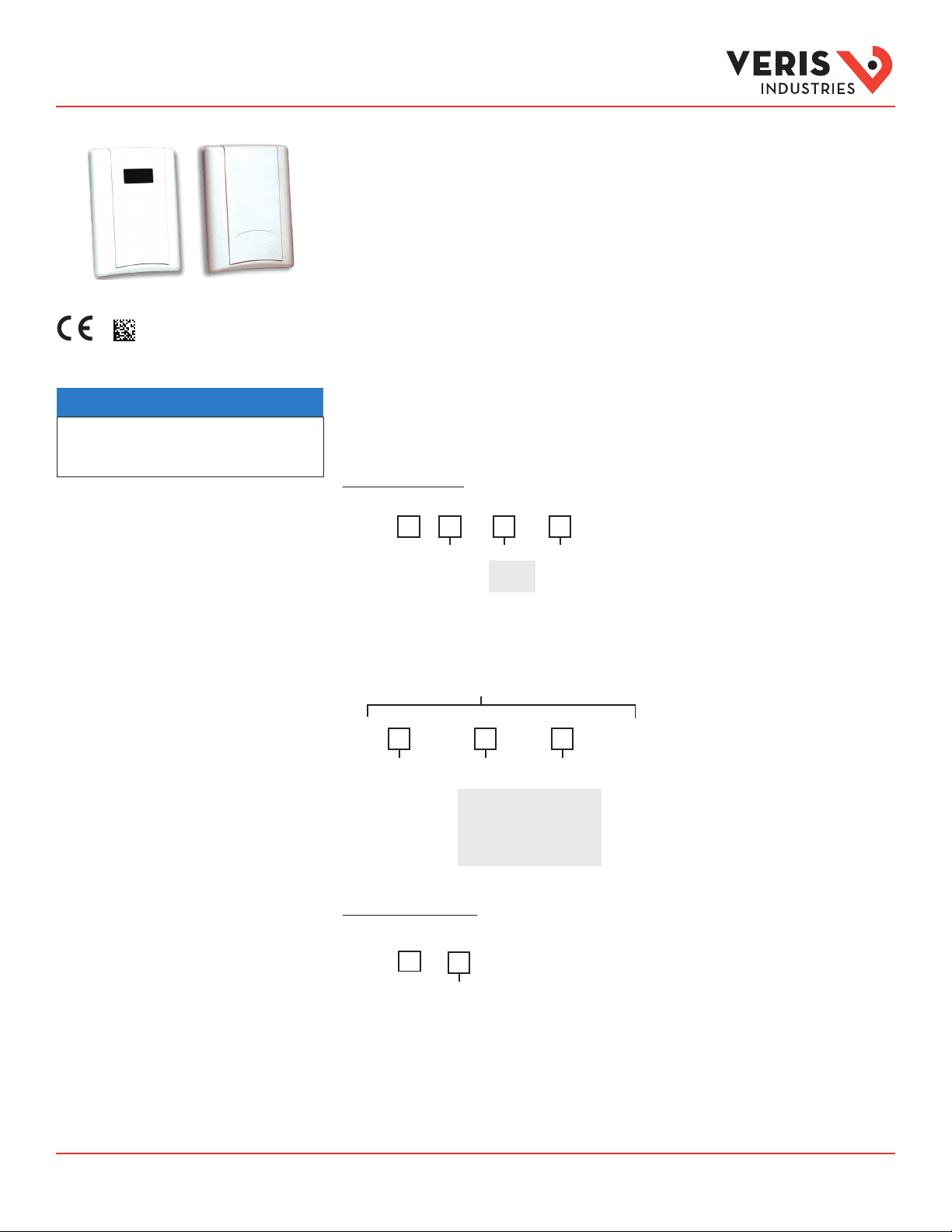
CW Series
Wall Mounted Environmental CO2 Sensors
Product Overview
CW Series wall mount CO2 sensors measure the levels of CO2, RH (if equipped), and temperature (if equipped)
of air inside a duct. The CO2 sensor operates within accuracy specications for an interval of ve years and can
be eld calibrated. The temperature element is warranted to meet accuracy specications for a period of ve
years. RH equipped models feature a replaceable HS Series humidity element that is warranted to meet accuracy
specications for a period of one year. To maintain accuracy, all vents must remain clear and free of dust, debris,
etc.
Product Identication
WALL DELUXE MODELS:
Temp
T = Temp
X = No
(stop here)
Sensor Type
A = Transmitter
B = 100R Platinum, RTD
C = 1k Platinum, RTD
D = 10k T2, Therm.
E = 2.2k, Therm.
F = 3k, Therm.
G = 10k CPC, Therm.
H = 10k T3, Therm.
J = 10k Dale, Therm.
K = 10k w/11k shunt, Therm.
M = 20k NTC, Therm.
N = 1800 ohm, Therm.
R = 10k US, Therm.
S = 10k 3A221, Therm.
T = 100k, Therm.
U = 20k “D”, Therm.
CWL
RH Option
S
H = RH 2%
X = No RH
Options Available
TM
Temp Cal Cert
X = No
1 = 1pt Temp Cal
2 = 2pt Temp Cal
1 = Push Button
Override *
2 = Set Point Slider
3 = Push Button
Override*+Set Point
Slider
WALL ECONOMY MODELS:
Sensor Type
S
CWE
B = 100R Platinum, RTD
C = 1k Platinum, RTD
D = 10k T2, Therm.
E = 2.2k, Therm.
F = 3k, Therm.
G = 10k CPC, Therm.
H = 10k T3, Therm.
J = 10k Dale, Therm.
Setpoint Slider Value
Option
A = 1k
F = 10k
G = 20k
K = 50k
M =1 00k
K = 10k w/11k shunt, Therm.
M = 20k NTC, Therm.
N = 1800 ohm, Therm.
R = 10k US, Therm.
S = 10k 3A221, Therm.
T = 100k, Therm.
U = 20k “D”, Therm.
* Note: the Pushbutto n Override
feature is not avai lable with
temperature transmitter models.
Only resistive temperature models
qualify f or this feature.
Z204903-0N Page 1 of 8 ©2016 Veris Industries 0816
Alta Labs, E nercept, Ensp ector, Hawkeye, Tru stat, Aerospo nd, Veris, and th e Veris ‘V’ log o are tradema rks or registe red tradema rks of Veris Ind ustries, L. L.C. in the USA and /or other countri es.
Other companies’ trademarks are hereby acknowledged to belong to their respective owners.
Page 2
CW Series Installation Guide
TM
Specications
Input Voltage Class 2; 20 to 30 Vdc, 24 Vac
Analog Output CWL : 4 to 20 mA (clipped and capped)/0-5 Vdc/0-10Vdc (selec table)
Sensor Current Draw 100 mA max.
Operating Temperature Range No humidit y option: 0 to 50 °C (32 to 122 °F)
Operating Humidity Range 0 to 95% (non-condensing)
Housing Material High impact ABS plastic
Sensor Type Non-dispersive infrared (NDIR), diusion sampling
Output Range CWL: 0 to 2000 ppm or 0 to 5000 ppm, user select able;
Accuracy ±30 p pm ±2% of measured value*
Repeatability ±20 ppm ±1% of measured value
Response Time <60 seconds for 90% step change
HS Sensor Digitally prole d thin-lm capacitive (32-bit mathematics);
Accuracy ±2% f rom 10 to 80% RH @ 25°C; Multi-p oint calibration NIS T
Hysteresis 1. 5% ty pical
Linearity Included in Accuracy spec.
Stability ±1% @ 20 °C (68 °F) annually for two years
Output Range 0 to 100% RH
Temperature Coecient ±0.1% RH/°C above or below 25 °C (typical)
Sensor Type Thermistor
Accuracy ±0. 5 °C (±1 °F) ty pical
Resolution 0.1 °C (0.2 °F)
Output Range 10 to 35 °C (50 to 95 °F)
1 Form C (on models without setpoint
slider option)
CWE: 4 to 20 mA (clipped and capp ed)/0-10Vdc (selec table)
With humidity option**: 10 to 35 °C (50 to 95 °F)
TRANSMITTER
CO
2
CWE: 0 to 200 0 ppm
RH TR ANSMIT TER**
U.S. Patent 5, 844,138
TEMPERATURE (TRANSMIT TER)**
REL AY CONTACTS**
1 A@30 Vdc, resistive; 30 W max.
Specified accuracy with 24 Vdc supplied power with rising humidity. RTD/Thermistors in wall packages are not compensated for
internal heating of product.
EMC Conformance: EN 61000-6-3:2007 Class B, EN 61000-6-1:2007
EMC Special Note: Connect this product to a DC distribution network or an AC/DC power adaptor with proper SURGE PROTECTION
(EN 61000-6-1:2007 specification requirements)
* Measured at NTP
** Not available on CWE
Note: Rough handling and transportation may cause a temporary reduction of CO2 sensor accuracy. With time, the ABC function will
tune the readings back to the correct accuracy range. The default tuning speed is limited to 30 ppm per week.
Z204903-0N Page 2 of 8 ©2016 Veris Industries 0816
Alta Labs, E nercept, Ensp ector, Hawkeye, Tru stat, Aerospo nd, Veris, and th e Veris ‘V’ log o are tradema rks or registe red tradema rks of Veris Ind ustries, L. L.C. in the USA and /or other countri es.
Other companies’ trademarks are hereby acknowledged to belong to their respective owners.
Page 3
CW Series Installation Guide
TM
4.75"
(121 mm)
1.15"
3.50"
FRONT VIEW
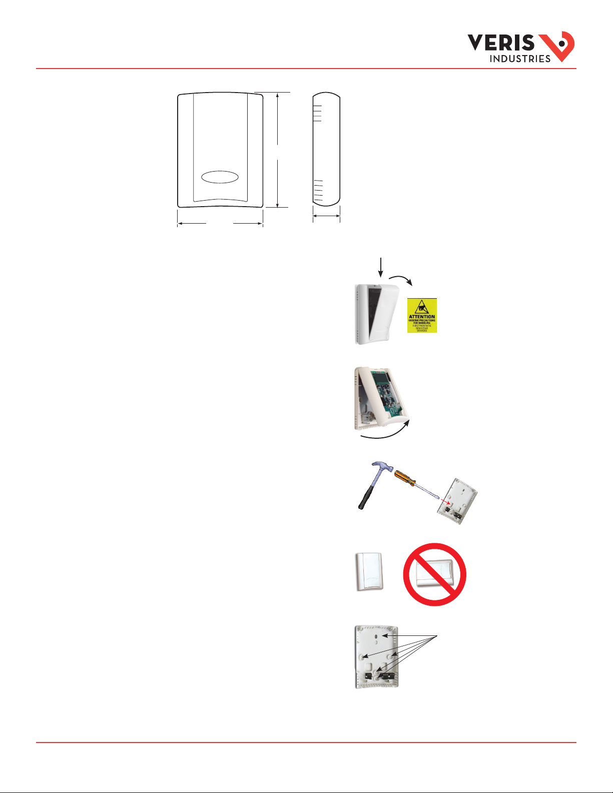
Observe precautions for handling static sensitive
Dimensions
Installation
1. Remove the cover by pressing the tab at at the top
of the sensor while pulling outward from the
top of the cover.
2. Remove the backplate by unfastening the sensor
from the bottom of the backplate and pivoting
the sensor outward.
3. Punch out desired wire openings in the backplate.
4. Position the sensor vertically on the wall, 4-1/2 feet
above the oor. Locate away from windows, vents,
and other sources of draf t. If possible, do not mount
on an external wall, as this might cause inaccurate
temperature readings.
devices to avoid damage to the circuitry that
is not covered under the factory warranty.
All optional connector
blocks are sho wn here for
cla rity.
5. Mount the backplate onto the wall using
the screws provided.
Five screwholes available; use a minimum
of two for secure m ounting.
All optiona l connector blocks are show n here for
cla rity.
Z204903-0N Page 3 of 8 ©2016 Veris Industries 0816
Alta Labs, E nercept, Ensp ector, Hawkeye, Tru stat, Aerospo nd, Veris, and th e Veris ‘V’ log o are tradema rks or registe red tradema rks of Veris Ind ustries, L. L.C. in the USA and /or other countri es.
Other companies’ trademarks are hereby acknowledged to belong to their respective owners.
Page 4

CW Series Installation Guide
TM
RTD/THERMISTOR/OVERRIDE
RTD/THERMISTOR/OVERRIDE
CO2 OUTPUT
RTD/THERMISTOR/OVERRIDE
RTD/THERMISTOR/OVERRIDE
Installation (cont.)
6. Wire the backplate.
CWL with RH and Temperatu re Transmitter O ptions
PWR
COMMON
CO2 OUTPUT
RH OUTPUT
TEMP OUTPUT
PWR
COMMON
CWL with RH, Th ermistor/RTD, Pushbutton Ove rride, and
+
POWER SUPPLY
20-30VDC, 24VAC
-
CONTROL SYSTEM
COMMON
-
CO2 INPUT
RH INPUT
TEMP INPUT
RELAY N.O.
COMMON
RELAY N.C.
RELAY N.O.
RELAY N.C.
COMMON
CWE
+
POWER SUPPLY
20-30VDC, 24VAC
-
CONTROL SYSTEM
COMMON
-
CO2 INPUT
THERMISTOR/OVERRIDE INPUT
PWR
COMMON
CO2 OUTPUT
RH OUTPUT
Setpoint Slider Options
SLIDER RIGHT
SLIDER LEFT
SLIDER WIPER
+
POWER SUPPLY
20-30VDC, 24VAC
-
CONTROL SYSTEM
COMMON
-
CO2 INPUT
RH INPUT
THERMISTOR/OVERRIDE INPUT
SETPOINT SLIDER INPUT
7. Install the sensor onto the backplate.
8. Use the switch to selec t voltage or current output.
For CWL model, see Conguration section.
9. When installation is complete, install the cover and
snap into place.
VOLT
AMP
Z204903-0N Page 4 of 8 ©2016 Veris Industries 0816
Alta Labs, E nercept, Ensp ector, Hawkeye, Tru stat, Aerospo nd, Veris, and th e Veris ‘V’ log o are tradema rks or registe red tradema rks of Veris Ind ustries, L. L.C. in the USA and /or other countri es.
Other companies’ trademarks are hereby acknowledged to belong to their respective owners.
Page 5

CW Series Installation Guide
TM
ABC Settings (CWE only)
Installation (cont.)
ABC Calibration
Algorithm
10. Programmable override button
11. Programmable setpoint slider
Setpoint slider
ABC (Automatic Baseline Calibration) is a patented self-calibration feature that automatically adjusts the CO2 sensor to
compensate for drif t. When ABC is enabled, the sensor records the lowest reading within every 24-hour interval and compares
these values over a running 7-day or 28-day period. If a statistically signicant amount of drift is detected, the ABC applies an
automatic correction factor. This enables the sensor to operate within specications for the 5-year calibration interval.
ON POSITION. Recommended Setting. Use the ON setting for applications where the building is unoccupied within a 24-hour
timeframe.
Override b utton
Note: the Pushbu tton Override
feature is not avai lable with
temperature transmitter models.
Only resistive temperature models
qualify f or this feature.
LOW POSITION. Use the LOW setting for buildings occupied 24 hours a day.
OFF POSITION. Not Recommended.
NOTE: After changing the ABC settings, power cycle the unit for changes to take eect.
To set the ABC mode for CWL models, refer to the Conguration section of this document.
To set the ABC mode for CWE models, position the ABC jumper as shown:
ON LOW
ON
LOW
OFF
ON
LOW
OFF
OFF
ON
LOW
OFF
Z204903-0N Page 5 of 8 ©2016 Veris Industries 0816
Alta Labs, E nercept, Ensp ector, Hawkeye, Tru stat, Aerospo nd, Veris, and th e Veris ‘V’ log o are tradema rks or registe red tradema rks of Veris Ind ustries, L. L.C. in the USA and /or other countri es.
Other companies’ trademarks are hereby acknowledged to belong to their respective owners.
Page 6

CW Series Installation Guide
TM
Output Scaling
CO2 - Carbon Dioxide Sensor
Output scaling: 0 to 2000 ppm
CO2 PPM 0 to 5 V Output 0 to 10 V Output mA Output
Outside 30 to 500 0.75 to 1.25 1.5 to 2.5 6.4 to 8
Over Ventilated Under 600 Under 1.5 Under 3 Under 8.8
Ideal Ventilation 600 to 900 1.5 to 2.25 3 to 4.5 8.8 to 11.2
Under Ventilated Over 900 Over 2.25 Over 4.5 Over 11.2
RH - Relative Humidity Sensor
Output scaling: 0 to 100%
T - Temperature Transmitter
Output scaling: 10° to 35°C (50° to 95°F)
To determine temperature from output reading:
1. Compute Total Span from Temperature Range:
Maximum range - Minimum range = Total span
ex. 10° to 35°C range: 35 - 10 = 25 Total span
2. Compute Output % of Span from Reading:
(Reading - Minimum Output) / (Maximum output - Minimum output)
ex. 11.10 mA reading on 4-20 mA output: (11.10-4) / (20-4) = 7.10 / 16 = 0.444 = 44.4%
ex. 4.44v reading on 0-10 V output: (4.44-0) / (10-0) = 4.44 / 10 = 0.444 = 44.4%
3. Compute Temperature:
(Total span x Output % of Span) + Minimum range
ex. 44.4% Output, Total Span = 45, range = 50/95: (0.444 x 45) + 50 = 20 + 50 = 70°
Example outputs for selected temperatures:
Temperature 4 to 20 mA 0 to 10 V 0 to 5 V
65 9.33 mA 3.33 V 1.67 V
70 11.10 mA 4.44 V 2.22 V
75 12.89 mA 5.56 V 2.78 V
Z204903-0N Page 6 of 8 ©2016 Veris Industries 0816
Alta Labs, E nercept, Ensp ector, Hawkeye, Tru stat, Aerospo nd, Veris, and th e Veris ‘V’ log o are tradema rks or registe red tradema rks of Veris Ind ustries, L. L.C. in the USA and /or other countri es.
Other companies’ trademarks are hereby acknowledged to belong to their respective owners.
Page 7

CW Series Installation Guide
TM
M0
PM 00150P
O.O
%R H
00
XX
00
ENAD
AM
BDOE
XXX
–+
CX
OE
RX
.X
–+
CA
*:00
WN
XX
SA
CA
Conguration - CWL Only
RUN MODE:
PP
CO2
CO2 ONLY MODEL
*INDICATES RELAY STATUS
CO2/RH COMBO MODEL
PM
P
ºF
CO2/T COMBO MODEL
PPM
XXX
CO2/RH/T COMBO MODEL
TOGGLE %RH AND DEGREES
10
0
7
10
X
CONFIGURATION MODE:
PRESS ENTER FOR CONFIGURATION MODE.
010
PRESS PLUS OR MINUS TO CHANGE SETTING.
S P OT
E NI T
PUSH AND HOLD PLUS AND MINUS FOR 5 SECONDS
TO ENTER MODE. PRESS ARROW TO CHANGE OPTION.
PUSH ENTER FOR N EXT SELECTIO N.
CALIBRATION MODE*:
E
R
LI
2C O 08 0
XX
X
RANGE 500 TO 1500
50 PPM INCR EMENT
DDBA
2CO 010
RANGE 10 TO 500
.
0
5 PPM INCR EMENT
DISPLAYS SERIAL NUMBER
X
X
XX
XXX
DISPLAYS MO DEL NUMBER
F.XS
F
XXX
X
T
º
RGEN
A
.
CO
2
OPTIONS ARE 2000 OR 5000
X
C
XX +X–
OPTIONS ARE ON, LOW, OFF
SEE PREVIO US PAGE FOR EXPLANATION
RANGE IS -5 TO 5 °C, 0.1 °C INCREMENT
(CO2/temp combo models)
F
FO
%
RANGE -10 TO 10%, 0.1% INCREMENT
O
S
HX
(CO2/temp combo models)
2
C
TE
?
U
*NOTE: This product is factory calibrated. The typical CO
sensor calibration interval is 5 year s, depending on specic site
installation factors . As of the date of this document, compliance
with ANSI/ASHRAE 62-2001 requires minimum o n-site accuracy
verication intervals of 6 months or per the building operation
and maintenance manual. Verif y accuracy using a comparison
to a known reference or the CO2 gas calibration kit available
from Veris Industries as AA01.
WARNING: CO2 sensor calibration requires gas calibration kit.
Performing calibration with out gas kit or at an incorrect gas
ow rate will cause erroneous readings.
Z204903-0N Page 7 of 8 ©2016 Veris Industries 0816
Alta Labs, E nercept, Ensp ector, Hawkeye, Tru stat, Aerospo nd, Veris, and th e Veris ‘V’ log o are tradema rks or registe red tradema rks of Veris Ind ustries, L. L.C. in the USA and /or other countri es.
2
Other companies’ trademarks are hereby acknowledged to belong to their respective owners.
N
SIXT
º
(TEMP M ODELS ONLY)
OPTIONS ARE °F or °C
O TUT
PU
1 0 V +0– –
(VOLTAGE MODE ONLY)
OPTIONS: 0 to 10 V OR 0 to 5 V
DEFAULT IS 0 to 10 V
O TUT
PU
2 0 m A4 –
(mA MODE ONLY)
X
XLX
OPTIONS ARE YES, NO
L
A
OPTIONS ARE NONE, 0, 400
RI
G
X–
XSXX+
KO
G
5
Unit will automatically retu rn to run mode
when calibration is complete.
?
Page 8

CW Series Installation Guide
TM
NITROGEN
GAS
Regulator
Valve
NITROGEN
GAS
Regulator
Valve
Calibration Process
CWL Models:
1. Remove cover and connect gas cylinder hose to the plastic port located on sensing
module. Note: only connect one sensor to the calibration gas cylinder at a time.
800 PPM
70.0 ˚F
2. Start owing nitrogen gas (0 ppm CO2). Use a ow rate of 0.3 to 0.5 liter/minute.
Connect hose
here
CWE Models:
1. Remove cover and connect gas cylinder hose to the plastic port located on sensing
module. Note: only connect one sensor to the calibration gas cylinder at a time.
LED
indicato r
Connec t
hose here
2. Start owing nitrogen gas (0 ppm CO2). Use a ow rate of 0.3 to 0.5 liter/minute.
3. Calibrate for 5 min. Unit will return to working display when nished.
800 PPM
70.0 ˚F
4. When unit returns to working display, remove hose from calibration port and enter
Calibration mode as described in the Installation section.
3. Push and hold down calibration button until the LED illuminates.
LED indicato r
Connect hose here
Calibration
button
4. Continue owing gas through the sensor until the LED is o. Estimated calibration
time is 5 minutes. Remove hose from calibration port when complete.
For more complete calibration instructions using the
AA01 Calibration Kit, see the AA01 Installation Guide.
Z204903-0N Page 8 of 8 ©2016 Veris Industries 0816
Alta Labs, E nercept, Ensp ector, Hawkeye, Tru stat, Aerospo nd, Veris, and th e Veris ‘V’ log o are tradema rks or registe red tradema rks of Veris Ind ustries, L. L.C. in the USA and /or other countri es.
Other companies’ trademarks are hereby acknowledged to belong to their respective owners.
 Loading...