

Page 1
VERIS INDUSTRIES
™
environmental SenSorS
NOTICE
• This product is not intended for life or safety applications.
• Do not install this product in hazardous or classified locations.
• Read and understand the instructions before installing
this product.
• Turn off all power supplying equipment before working on it.
• The installer is responsible for conformance to all applicable codes.
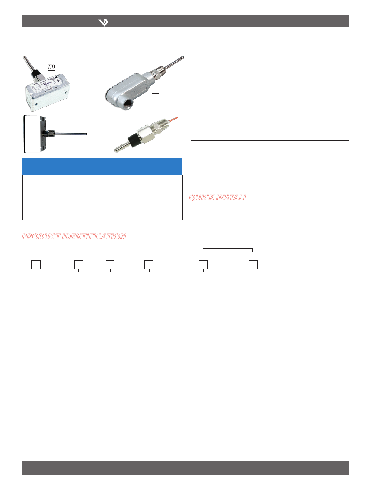
inStallation GUiDe
TI SerIeS TI SerIeS
TID
TIW
Product IdentIfIcatIon
Immersion Probe
Enclosure
T I
D = Duct
G = Servi ce Entry Body
H = Threade d NPT Only
W = Water resis tant
housing
Length “L”
A = 2 1/2" (64mm)
B = 4" (102mm)
C = 6" (152mm)
D = 8" (203mm)
E = 12” (305mm)
Thermowell Sizing
Probe Length Thermowe ll Length
A (2 1/2") (64mm) 1 1/2” (38mm)
B (4") (102mm) 3” (76mm)
C (6") (152mm) 5” (127mm)
D (8") (203mm) 7” (178mm)
E (12”) (305mm) 11” (279mm)
Thermowell Sensor Type
0 = None
1 = Add Therm owell
TIG
TIH
B = 100R Platinu m, RTD
C = 1k Platinum, RTD
D = 10k T2, Therm istor
E = 2.2k, Ther mistor
F = 3k, Therm istor
G = 10k CPC, Ther mistor
H = 10k, T3, Ther mistor
J = 10k Dale, Ther mistor
K = 10k w/11k shunt,Thermistor
M = 20k NTC, Ther mistor
N = 1800 ohm, Ther mistor
P = 10mV/°C, Linitemp
R = 10k US, Thermis tor
S = 10k 3A221, Thermis tor
T = 100k, The rmistor
U = 20k “D”, Thermis tor
Immersion Temperature Sensors
Installer’s Specifications
Wiring 22AWG; 2-wire:RTD Thermistor, 4-20mA; 3-wire: Voltage output models
Probe Stainless Steel
Test Pressure 200psi
Linitemp:
Input Power 5 to 30VDC
Output 1µA/°C or 10mV/°C
Operating Temperature -25° to 105°C (-13° to 221°F)
Accuracy C alibration Error: 1.5°C (35°F) typic al; 2.5°C (37°F) max. at 25°C (77°F )*
Error over Temperature: 1.8°C typical (35°F); 3.0°C (34°F) max.
over 0° to 70°C (32° to 158°F) range
2.0°C (35°F) t ypical, 3.5°C (38°F) max.
over -25° to 105°C (-13° to 221°F) range
*Room temperature error do cumented on each unit.
quIck Install
Thread assembly into a pipe fitting.1.
Wire as shown (see Wiring sec tion).2.
Options
Cal Certificate
0 = None
1 = 1 point Cal v alidation
2 = 2 point Cal v alidation
Threads
Blank = NPT
A = BSPT
B = DIN 2999
Z205466-0E PAGE 1 ©2009 Veris Industries USA 800.354.8556 or +1(0)503.598.4564 / support@veris.com 10091
Alta Labs, Enercep t, Enspector, Hawkeye, Trustat, Veris, and the Veris ‘ V’ logo are trademark s or registered tradema rks of Veris Industries, L.L .C. in the USA and/or othe r countries.
Page 2

VERIS INDUSTRIES
™
dImensIons
1.5"
(38 mm)
0.25"Dia.
(6.3 mm)
L
1/2" NPT
Standard
L
L
0.25" dia.
(6.3mm)
Overall: "L" + 2" (50.8mm)
0.375" dia.
(10mm)
Overall: "L" + 1.75" (45mm)
Immersion Probes
Thermowells
4"
(102 mm)
2.2"
(56 mm)
0.25" dia"
(6.3mm)
L
0.5" nom.
(13 mm)
CONTROLLER
TEMP SENSOR
+15v
Analog IN
Common
CONTROLLER
TEMP SENSOR
+15v
Analog IN
Common
4.5"
(114 mm)
2.8"
(71 mm)
0.25" dia"
(6.3mm)
L
1.5"
(38 mm)
1/2" NPT
Standard
TIG Model
TIH Model
ti SerieS
inStallation GUiDe
TIW Model
TID Model
Z205466-0E PAGE 2 ©2009 Veris Industries USA 800.354.8556 or +1(0)503.598.4564 / support@veris.com 100 91
Alta Labs, Enercep t, Enspector, Hawkeye, Trustat, Veris, and the Veris ‘ V’ logo are trademark s or registered tradema rks of Veris Industries, L.L .C. in the USA and/or othe r countries.
WIrIng
Thermistor
RTD
Linitemp
NOTE: All linitemp units are standard 3-wire 10m V/C. For 1µ A/C (2-wire)
connect +15V (orange) and (white) signal wire. The (blue) wire is not
connected.
Orange
Orange
ORANGE V+ (15V)
WHITE SIGNAL
BLUE COMMON/GND
3-Wire 10m V/C
ORANGE V+ (15V)
WHITE (SIGNAL )
BLUE (COMMON/GND)
2-Wire 1µ A/C
ORANGE V+ (15V)
WHITE (SIGNAL )
BLUE (NO CONNECT)
 Loading...