

Page 1
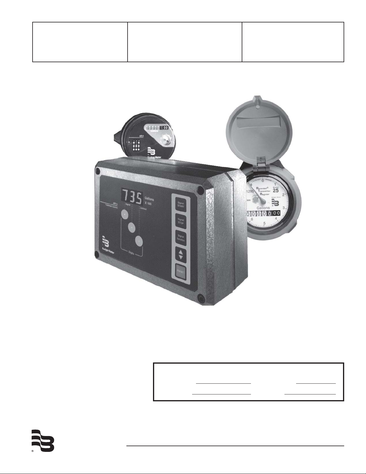
Model AR/e – AR/t
& RTR
Water Treatment Control System
Installation &
Operation Manual
BadgerMeter,Inc.
IMPORTANT !!!! Read this manual before
attempting any installation, wiring or operation.
Service Information (File manual for future reference and service.)
Serial Number Date Installed / /
Service Line Operator
IOM-034-13
Part No. 53400-034
3-09
Page 2
■
SCOPE OF THE MANUAL
This manual contains information concerning the installation,
operation and maintenance of the AR/e with AR/t or RTR Water
Conditioning Control System. To ensure proper performance
of the system, the instructions given in this manual should be
thoroughly understood and followed.
Keep the manual in a readily, accessible location for future
reference.
Changes and additions to the original edition of this manual will
be covered by a "Change Notice" supplied with the manual. The
change notice will explain any differences between the product
received and the product described in this manual.
■
TABLE OF CONTENTS
Page
Unpacking and Inspection .................................................. 2
INSTALLATION
Surface Mounting or Pipe Mounting .................................. 3
Panel Mount ......................................................................... 3
Wiring Precautions & Procedures ...................................... 3
Battery Installation ............................................................. 3
AC Power Connections ........................................................ 3
Transmitter Connections (AR/t & RTR).............................. 4
Lockout Signal Connections ............................................... 4
Remote Start & Stop Connections ..................................... 4
Connecting to Other Equipment ........................................ 5
OPERATION
Forced Regeneration ........................................................... 6
Aborting Regeneration cycle .............................................. 6
Overriding Preset Batch Value ........................................... 6
PROGRAMMING
General Programming Procedures ..................................... 5
Setting For Manual/Auto Operation ................................... 5
Setting AR/e to Type & Size of Meter ................................ 5
Batch Size ............................................................................ 6
Output Signal Duration ....................................................... 6
Start-up Check List ............................................................. 6
■
UNPACKING & INSPECTION
To avoid damage in transit, Badger products are shipped to the customer in special shipping containers. Upon receipt of
the product, perform the following unpacking and inspection procedures.
Note: If damage to the shipping container is evident upon receipt, request the carrier to be
present when the product is unpacked.
a. Carefully open the shipping container following any instructions that may be marked on the box. Remove all cushioning material surrounding the product and carefully lift the
product from the container.
Retain carton and packing material for use in re-shipment
or storage of unit.
b. Visually inspect the product and applicable accessories for
any physical damage such as scratches, loose or broken parts
or any other sign of damage that may have occurred during
shipment.
Note: If damage is found, request an inspection by the
carrier's agent within 48 hours of delivery and file a claim
with the carrier. A claim for equipment damaged in transit
is the sole responsibility of the customer.
■
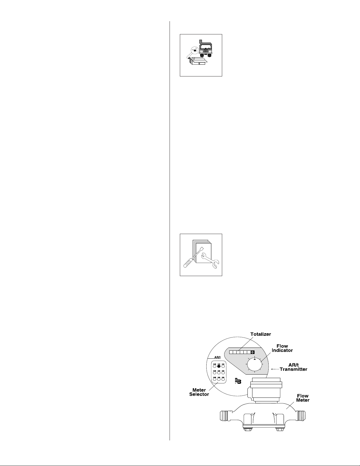
INSTALLATION
The AR System consists of a Badger Disc
or Turbo meter with the AR/t or RTR
pulse transmitter and the AR/e Condi-
tioning Controller. Normally, the trans-
mitter will be mounted on the meter. It
does not require any additional mount-
ing procedure. All transmitters use a
simple bayonet mount and a seal screw to
attach to the meter.
Note: Always be sure to match the transmitter to the proper
meter. A red dot on the AR/t transmitter dial indicates the
meter model and size for which the transmitter is intended.
The RTR dial face has the model designation of the appropriate meter.
TROUBLESHOOTING
Self-test Procedure .............................................................. 6
Replacement Parts ............................................................... 6
Troubleshooting Chart ........................................................ 7
2
Page 3
MOUNTING
The AR/e controller comes in a rugged, watertight polycarbonate enclosure intended for wall, pipe or panel mounting. The
package contains two sets of mounting screws and "O" rings
which must be used to maintain the NEMA 4X rating of the
enclosure.
When mounting the unit select a location which has adequate
ventilation, protection against mechanical shock and accessibility for operation and service.
Operating Temperature: 32° to 130° F (0° to 55° C)
Operating Humidity: Up to 85% non-condensing
Using a 5/32'' Allen wrench, remove the four corner screws in
the housing.
Separate the front and rear halves of the housing. Keep the
screws and housing gasket in an accessible location.
WIRING PROCEDURE
Three plug-in terminal block assemblies are provided for
connecting 28 to 14 gauge insulated wire. Solid or stranded
wire can be used.
It is recommended that wiring be carefully planned and laid
out before installation. This will help determine the amount of
space needed for wiring as well as the final location of the unit.
Detail diagrams in this section illustrate proper wiring procedures for all standard and optional functions.
Be sure to comply with the wiring requirements and all applicable electrical codes.
Note: Terminal block assembly unplugs from printed circuit
board for ease in connecting field wiring.
Disconnect all power to the unit before connecting wires to
any of the terminals. Do not use machine power service. A
dedicated or lightning circuit is recommended.
INSTALL BATTERY ON CIRCUIT BOARD ONLY
AFTER WIRING IS COMPLETED.
Wall or Pipe Mount
1. Using the appropriate mounting hardware attach the back
part of the housing to the mounting surface.
2. Wire the unit (see wiring procedures on this page).
3. Carefully place the housing gasket in place and bolt the
front part of the housing to the back part.
Panel Mount
1. Use the housing gasket to mark and drill the panel.
2. Drill a 3/4" hole in the panel for the fuse holder.
3. Wire the unit (see wiring procedures on this page).
4. With the housing gasket properly placed on the front
housing, mount the unit to the panel.
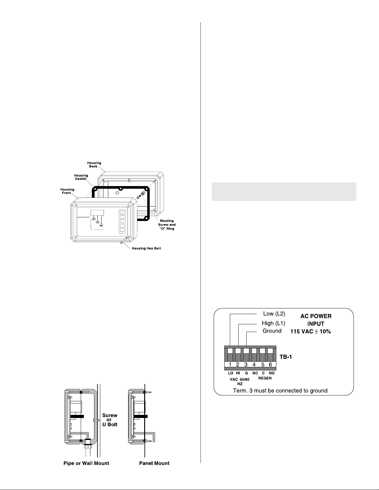
POWER INPUT
The AR/e is designed to work with a 110 VAC power supply. In
case of power failure, the unit will retain all programmed
values and continue to count down (without display or output)
for several hours. When power is restored, the unit will send an
output signal if enough pulses have accumulated during power
outage. If the power down period exceeds the battery capacity,
the last known batch count and other programmed values will
be stored until the power comes back on. (Battery requires a
minimum of 24 hours to recharge from a fully discharged
condition.)
3
Page 4

PULSE INPUT (AR/t)
The AR/t transmitter sends pulse signals to the AR/e controller.
Each pulse represents a specific quantity of water for a
particular meter size.
Meter Pulse Rate
RCDL Models 25, 35 and 40 1 pulse = 1 Gallon
RCDL Models 70, 120, 170 and
Industrial Turbo 2", 3" and 4" 1 pulse = 10 Gallons
Industrial Turbo 6" 1 pulse = 100 Gallons
Reed switch transmitters have two black leads. Connect these
leads to terminals 1 & 2 in any order.
Electronic transmitters have one black lead and one white
lead. Connect these leads as per the diagram at right.
In the Automatic mode, the relay will be energized at the end
of the batch for the amount of seconds programmed via the
SIGNAL DURATION procedure (see page 6). The relay contacts can be wired to a timer or regeneration cycle controller.
REMOTE START & STOP (OPTIONAL)
Remote Start Input
When activated, it will abort a batch before its completion,
initiating tank regeneration at the same time.
In the Manual mode, the output relay will be energized
indefinitely and the display will be reset to zero until the STOP
command is received.
PULSE INPUT (RTR)
The RTR transmitter/register sends pulse signals to the AR/e
controller. Each pulse represents a specific quantity of water
for a particular meter size.
Meter Pulse Rate
RCDL Models 25, 35, 40, & 70 1 pulse = 1 Gallon
RCDL Models 120 and 170 1 pulse = 10 Gallons
RCDL Turbo Series 1 1/2" - 6" 1 pulse = 100 Gallons
These transmitters have one black lead and one red lead.
Connect these leads as per the diagram.
In the Automatic mode, the output relay will be energized for
the programmed duration (see operation section page 6) and
the display will be reset to the batch preset value and continue
to count down when pulses are received.
If a START command is received while the LOCKOUT is active,
the command will be stored in memory and acted upon as soon
as the LOCKOUT signal is terminated.
Remote Stop Input
Is used to terminate the output signal. This function is enabled
after a START command is received or after the output relay
is energized at the end of the batch.
In the Manual mode, it will terminate the output signal, reset
the counter to the batch preset value and enable the transmitter pulse input.
In the Automatic mode, it will only terminate the output signal.
RELAY OUTPUT
The regeneration signal relay is energized at the end of the
batch or when a START command is initiated.
In the Manual mode, the relay will remain energized until the
SIGNAL STOP is initiated. The relay contacts can be used to
activate a warning device to indicate that manual regeneration of the system is necessary.
LOCKOUT INPUT (OPTIONAL)
To avoid simultaneous regeneration of multiple tanks, a lockout signal can prevent a controller from sending a regeneration signal at the end of the batch.
4
Page 5

The regeneration signal will be sent as soon as the lockout
signal is terminated. A lighted decimal point at the lower right
corner of the display will indicate the presence of a lockout
signal. (An open collector/switch contact or a 115 VAC signal
can be used as the lockout signal.) When using a 115VAC
lockout signal, the lockout logic can be reversed. (See settings
for Switch 2 in section below.) If the 115VAC lockout signal is
not used, Switch 2 must be in the off position. The lockout
signal will be ignored if the output is energized.
■
OPERATION
The basic function of the AR/e controller
is to provide a signal to external equipment once a predetermined amount of
water has been measured by the water
meter. The batch is preset and the display counts down to zero. At this point
the output relay is energized for a programmed period of time providing the necessary signal for
manual or automatic regeneration.
The controller is designed to function with a minimum of
operator control after the initial setup procedures. All displays
and controls are located on the front panel for fast, accurate
and convenient operation.
GENERAL PROGRAMMING PROCEDURE
In addition to the LED display and the digit keys, the front
panel of the AR/e controller has two command keys (START
and STOP) and three program keys (PRESET, SIGNAL DURATION and UP-DOWN COUNT).
SELECTING THE MODE OF OPERATION
Select the mode of operation and maximum batch size required for your particular system. (For location of switches,
see page 7.)
Switch 1: ON (Manual operation)
OFF (Automatic operation)
Switch 2: ON (Lockout when 115VAC is not applied
to TB-3)
OFF (Lockout when 115VAC is applied to TB-3)
Note: Switch 2 must be in the off position when not using 115
VAC lockout function.
Switches 3 & 4: (See chart) Set switches for the maximum
batch size for your particular size of meter.
Example: You have a 2" Industrial Turbo meter and your batch
size is 500000 gallons, set switch 3 to the off position, and set
switch 4 to the off position. (This will allow you to set a maximum
batch size of 999000 gallons.) Attach the X1000 sticker to the
front panel.
Batch Capacity Selection Table
Attach appropriate multiplier label to front panel.
Switch
Position
1234
1234
1234
X100
1234
X1000
Zeros are not displayed.
on
RCDL 25, 35,
40 & 70 (RTR)
X1
X10
(no label)
Max. Preset Value in US Gal.
for Meter Size (inches)
RCDL 70 (AR/t),
120 & 170 and
Ind. Turbo 2", 3" & 4"
999
blank
X10
99900 9990000999000
X1000
9990 99900
X10
999009990 999000
(no label)
X1000
X10000
Turbo Series
1 1/2" - 6" and
Ind. Turbo 6"
(no label)
99900000999000 9990000
X1000
X10000
X100000
To prevent tampering or accidental mistakes, the keys must be
depressed twice in succession for the command to be recognized and acted upon. If the second command is not received
within ten seconds of the first, the unit will revert back to its
previous operation.
PROGRAMMING SEQUENCE
To interrogate the present value of a programmable function,
depress the appropriate function key. The display will show
the function symbol and the present value of the function
alternately for ten seconds and then revert back to normal
operation.
To preset a new value, press the appropriate key and change
the value by using the "digits" keys. Pressing a digit key
continuously will cause the number to scroll. When the desired
number is reached, remove your finger from the digit key.
Change one digit at a time, within ten seconds of each other.
After the new value is displayed, press the key again, to store
it in memory.
The unit will not react to any new values until it counts down
to zero. To accept the new values immediately, "zero" the unit
using the UP/DOWN key.
5
Page 6

■
TROUBLESHOOTING
Most problems encountered when applying the AR/e control
are due to wiring errors, improperly set functions or faulty
transmitter connections. This section provides guidelines for
the detection and correction of these and other problems.
However, should the problem persist, contact our nearest
representative or the factory for further assistance.
SELF TEST PROCEDURE
®
1. Switch power off and on again. If the displays shows
anything but three eights, an error exists in the processor
and the unit has to be replaced.
The START and STOP command
keys have the same effect as the
equivalent remote functions (see
wiring section on page 4). The key
must be depressed twice in succession for the command to be recognized and acted upon.
The PRESET key is used to set the
amount of water to be measured before
tank regeneration is required. The preset value is a three digit variable number times a multiplier.
Depress the key and the display will show the present preset
batch value and the preset symbol. Use the digit keys to set the
new value. Depress the PRESET key again to enter the new
value in memory.
The UP/DOWN key is used to "zero" the
unit or change the present count to a
larger or smaller number in order to
avoid simultaneous regeneration in multi-tank systems. The
new number will affect the batch in progress.
• Depress the key and the display will show the present
batch count and the UP/DOWN symbol.
• Use the digit keys to change the count value.
• Depress the UP/DOWN key again to enter the new count
value in memory.
2. If self test is satisfactory proceed to test the input switches
as follows:
a. Press the hidden test switch twice. At first the display
will show three fives then one eight.
b. Press all keys once in the following sequence: Signal
START (7) , Signal STOP (6), Signal Duration (5), UP/
DOWN (4), PRESET (3), Hidden Test Switch (2), least
significant digit (1), center digit (0), and most significant digit (Batch Count). Each time a key is depressed
the appropriate number will be displayed. If one of the
numbers remain in display after the next key is depressed, that particular input is defective.
■
START-UP CHECKLIST
1. Set DIP switch 1 for manual or automatic operation.
2. Set DIP switch 2 for proper lockout operation. (Set to "off"
position if not used.)
3. Set internal DIP switches (3 & 4) for meter size and
maximum batch size.
4. Install NiCad battery.
5. Program unit for batch size wanted.
6. Program unit for output signal duration wanted.
The SIGNAL DURATION key is used to
preset the time period for which the
output relay will remain energized at
the end of a batch, or when a START
command is received. The default value for signal duration is
5 seconds. This function is valid only if the control is set to
operate in the automatic mode. The duration can be programmed from 1 to 999 seconds.
• Depress the key and the display will show the present
signal duration period and the function's symbol.
• Use the digit keys to change the period.
• Depress the SIGNAL DURATION key again to enter the
new value in memory.
The SELF TEST key is used to run a self
test procedure in case of malfunction.
The procedure itself and the diagnostic
is explained in the Troubleshooting section on this page.
7. "Zero" the unit using UP/DOWN key.
■
FIELD REPLACEABLE PARTS
The following parts can be obtained locally. Brand names and
model numbers are for reference only.
Relay: Potter & Brumfield® T81H5D212-05 (or equal)
Fuse: Fusetron® slow blowing 1/10 amp MDL series
(or equal)
Battery: Eveready® CH22 7.2 volt NiCad rechargeable
battery
(Do not use non-rechargeable battery.)
If you find it necessary to send unit to factory, contact your
Badger representative or dealer for material return authorization. Package the unit properly, and include a brief description of the problem.
6
Page 7

PROBLEM POSSIBLE CAUSES REMEDIES
Display does not light when 1. No power on terminals 1 and 2. 1. Connect terminals 1 and 2 to power source.
AC power is turned on. 2. Blown fuse. 2. Replace fuse.
3. Shorted power wiring. 3. Remove short circuit.
Counter does not decrement 1. No flow through meter. 1. Establish flow through meter.
when transmitter is activated. 2. Defective transmitter. 2. Replace transmitter
3. Transmitter improperly connected. 3. Correct wiring error.
4. Dip switches improperly set. 4. Verify switch settings for your meter size.
Regeneration output is not 1. Defective relay. 1. Replace relay. (See page 7.)
energized at end of batch or 2. Lockout is active. 2. Check switch 2 position and wiring to
when a START command is lockout terminals.
received. (Signal indicator is lit.)
Cannot change programmed 1. Function key is not being pressed 1. Refer to page 6 for proper programming
values. twice. sequence.
2. Unit not "zeroed" with UP/DOWN 2. Use UP/DOWN key to "zero" unit, which will
key. force acceptance of new values.
Regeneration signal is active 1. Output is improperly wired. 1. Correct wiring errors.
when signal light is off. 2. Unit is defective. 2. Replace unit.
Test procedure does not work. 1. Unit is defective. 1. Replace unit.
Memory does not function 1. Battery is defective. 1. Replace battery.
during power outage.
AR/e Circuit Board
7
Page 8

Please see our website at
www.badgermeter.com
for specific contacts.
Copyright © Badger Meter, Inc. 2009. All rights reserved.
Due to continuous research, product improvements and enhancements,
Badger Meter reserves the right to change product or system specifications
without notice, except to the extent an outstanding bid obligation exists.
BadgerMeter,Inc.
P.O. Box 245036, Milwaukee, WI 53224-9536
Telephone: (414) 355-0400 / (800) 456-5023
Fax: (414) 355-7499 / (866) 613-9305
www.badgermeter.com
 Loading...