

Page 1
Installation Guide
Pressure Monitoring
Installation Guide
Pressure Monitoring
Installation Guide
Pressure Monitoring
Installation Guide
Pressure Monitoring
TMTMTM
TM
Product Identication
Dimensions
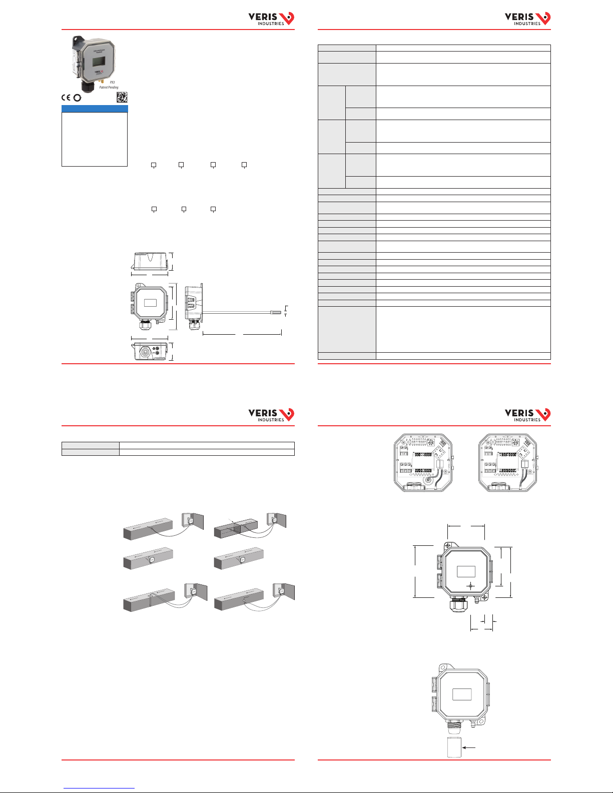
Product Overview
The PX3 transducer c an measure either air pressu re or velocity with the i p of a switch.
The PX3 is available in thre e installation congura tions: duct, panel or unive rsal. Duct and
panel models have two p ressure and velocity op tions: 0-1 in. WC / 0-3,000 ft/min or
1-10 in. WC / 3,000-6,000 ft/min w ith four eld-selec table sub-ranges. T he universal
model comes in one pre ssure/velocity ran ge: 0-10 in. WC / 0-7,000 ft/min w ith seven
eld-selec table sub-ranges for p ressure and eight for veloci ty. All variants are available
with and without di splay. The PX3 has an IP65/NEMA 4 environmenta l rating and a 5-year
limited warranty.
PX3 Series
Differential Pressure / Air Velocity Transducer
in. (mm)
PX3
Patent Pending
Media Compatibility Dry air or iner t gas
Input Power Three-wire Volt mod e: 24 Vac or 12-30 Vdc*
Two-wire mA mode: 12-30 Vdc*
Output Power Field-selectable: 2-wire, loop-powered 4-20 mA
Minimum input vol tage for 4 to 20 mA operatio n: 250 Ω loop = 12 Vdc; 500 Ω loop = 19 Vdc
(DC only, clipped and c apped), 24 Vac/dc or 3-wire 0 -5V/0-10V
Minimum load resi stance for Volt operati on: 5 kΩ
01 Pressure
Range
Pressure
Mode
Unidirectio nal: 0.1/0.25/0.5/1 in. WC FS, switch selec table
Bidirectio nal: ±0.1/±0.25/±0.5/±1 in. WC FS, switch selectab le
Unidirectio nal: 25/50/100/250 Pa FS, switch selec table
Bidirectio nal: ±25/±50/±100/±250 Pa FS, switch selectabl e
Velocity
Mode
500/1,000/2,000/3,000 ft/min
2.5/5/10/15 m/s
02 Pressure
Range
Pressure
Mode
Unidirectio nal: 1.0/2.5/5/10 in. WC FS, switch selec table
Bidirectio nal: ±1.0/±2.5/±5/±10 in. WC FS, switch sel ectable
Unidirectio nal: 250/500/1,000/2,500 Pa FS, s witch selectabl e
Bidirectio nal: ±250/±500/±1,000/±2,500 Pa FS, switch se lectable
Velocity
Mode
3,000/4,000/5,000/6,000 ft/min
15/20/25/30 m/s
05 Pressure
Range
Pressure
Mode
Unidire ctional: 0 .1/0.25/0.5/1/2.5/5/10 in . WC FS, switc h select able
Bidire ction al: ±0.1/±0.2 5/±0.5/±1/±2.5/± 5/±10 in. WC FS, sw itch sel ectab le
Unidirec tional: 25/50/100/250/500/1,00 0/2,500 Pa FS, sw itch selecta ble
Bidire ction al: ±25/±50/±100/± 250/±500 k/±1,000/± 2,500 Pa F S, switch select able
Velocity
Mode
500/1,000/2,000/3,000/4,000/5,000/6,000/7,000 ft/min
2.5/5/10/15/20/25/3 0/35 m/s
Response Time Standard: T95 in 20 sec, Fas t: T95 in 2 sec, DIP switch s electable
Mode Unidirectional or bidirectional, DIP switch selectable
Display (Option) Pressure mode: Signed 3 -1/2 digit LCD, indicates pressure, overran ge indicator
Velocity mode : Signed 4-1/2 digit LCD, indicates velo city, overrange indicat or
Proof Pressure 3 psid (20, 600 Pa)
Burst Pressure 5 psid (34, 500 Pa)
Pressure Mode Accuracy ±1% FS (combined lin earity and hysteres is)
Velocity Mode Accuracy ±90 ft/min (±0.45 m/s) plus 5% of measu red value**
Temperature Eect 1” (250 Pa) models: 0.05%/°C; 10” (2,50 0 Pa) models: 0.01%/°C
(Relative to 25 °C) 0 to 50 ° C (32 to 122 °F)
Zero Drif t (1-year) 1” (250 Pa) models: 2.0% max. ; 10” (2,500 Pa) models: 0.5% ma x.
Zero Adjust Pushbutton auto-zero and digital input (2-position terminal block)
Operating Environment 0 to 60 °C (32 to 140 °F)
Altitude of Operation 0 to 3,000 m
Pollution Degree 2
Humidity Range 100% RH, non-condensing
Mounting Location For indoor use only.
Fittings Brass barb; 0.24” (6.1 mm) o.d.
Suggested Cable Shielded:
Belden #9939 (22 AWG) 3-wi re multi-conduct or (or similar)
Belden #994 0 (22 AWG) 4-wire multi-co nductor (or similar)
Belden #9939 (22 AWG) 5-wi re multi-conduc tor (or similar)
Unshielded:
Belden #84 43 (22 AWG) 3-wire multi-condu ctor (or similar)
Belden #84 44 (22 AWG) 4-wire multi- conductor (or similar)
Belden #84 45 (22 AWG) 5-wire multi-cond uctor (or similar)
Environmental Rating IP65, NEMA 4
Specications
Installation, Wiring
& Conguration
FILTER
LOW
HIGH
AIR FLOW
AIR FLOW
AIR FLOW
AIR FLOW
Static Pressure
Panel Installations
Duct Installations
Dierential Pressure
1. Pl an the installation. Panel or du ct mount?
For velocity app lications, use the VFXP Se ries air velocity/measurem ent probe or AA18,
AA19 or AA20 velocity pitot tub es. For use with the PX3P (panel) a nd PX3U (universal)
models in Velocity mode only. Sold separately.
2. For duc t mount applications, thre ad the probe into the back of the d evice housing, as
shown in the dimensional drawing.
3. Congu re the internal tubing for th e selected installat ion method as describe d below.
Duct mount tubing conguration:
a. Connect the rig ht-side tube to the rear brass bar b marked as “-” on the
underside of the device housing.
b. Connect the lef t-side tube to the probe in the b ack of the device housing.
Panel mount tubing conguration:
a. Connect the rig ht-side tube to the rear brass bar b marked as “-” on the
underside of the device housing.
b. Connect the lef t-side tube to the front bra ss barb marked as “+” on the
underside of the device housing.
Installation, Wiring
& Conguration (cont.)
Specications (cont.)
4. Mount the transduce r (see the screw hole diagram be low).
5. For applicatio ns using conduit, remove the cab le gland nut on the bottom of th e unit.
Thread a standard 1/2-inch N PT female threaded coupler o nto the body of the cable
gland. Connect the o pposite end of the coupler to th e conduit.
Tubing for Duct Mount Tubing for Panel Mount
Tubing for Duct Mount
Tubing for Panel Mount
2.3
(59)
CTR-CTR
3.3
(83)
CTR-CT
R
2.5
(62)
To Pickup
Tube
1.4
(35)
To Pickup Tube
0.5
(13)
3.2
(81)
in. (mm)
NOTICE
•
This product is not intended for life or
safety applications.
• Do not install this product in hazardous
or classied locations.
•
Read and understand the instructions
before installing this product.
• Turn o all power supplying equipment
before working on it.
•
The installer is responsible for
conformance to all applicable codes.
If this product is used in a manner not specied
by the manufacturer, the protection provided
by the product may be impaired. No
responsibility is assumed by the manufacturer
for any consequences arising out of the use of
this material.
AIR FLOW
Z207504-0D Pa ge 3 of 8
©2018
Veris Indus tries 12345 SW L eveton Dri ve, Tualatin, O R 97062 USA / 800. 354.8556 or +1.503.598.456 4 / suppor t@veris .com 0518
Alta Labs, Ener cept, Enspec tor, Hawkeye, Trus tat, Aerosp ond, Veris, an d the Veris ‘V ’ logo are trad emarks or r egistere d trademark s of Veris Indu stries, L. L.C.
in the USA and/or ot her countri es. Other co mpanies’ t rademark s are hereby ac knowledg ed to belong to t heir respe ctive owne rs.
Z207504-0D Pa ge 1 of 8
©2018
Veris Indus tries 12345 SW L eveton Dri ve, Tualatin, O R 97062 USA / 800. 354.8556 or +1.503.598.456 4 / suppor t@veris .com 0518
Alta Labs, Ener cept, Enspec tor, Hawkeye, Trus tat, Aerosp ond, Veris, an d the Veris ‘V ’ logo are trad emarks or r egistere d trademark s of Veris Indu stries, L. L.C.
in the USA and/or ot her countri es. Other co mpanies’ t rademark s are hereby ac knowledg ed to belong to t heir respe ctive owne rs.
Z207504-0D Pa ge 4 of 8
©2018
Veris Indus tries 12345 SW L eveton Dri ve, Tualatin, O R 97062 USA / 800. 354.8556 or +1.503.598.456 4 / suppor t@veris .com 0518
Alta Labs, Ener cept, Enspec tor, Hawkeye, Trus tat, Aerosp ond, Veris, an d the Veris ‘V ’ logo are trad emarks or r egistere d trademark s of Veris Indu stries, L. L.C.
in the USA and/or ot her countri es. Other co mpanies’ t rademark s are hereby ac knowledg ed to belong to t heir respe ctive owne rs.
Z207504-0D Pa ge 2 of 8
©2018
Veris Indus tries 12345 SW L eveton Dri ve, Tualatin, O R 97062 USA / 800. 354.8556 or +1.503.598.456 4 / suppor t@veris .com 0518
Alta Labs, Ener cept, Enspec tor, Hawkeye, Trus tat, Aerosp ond, Veris, an d the Veris ‘V ’ logo are trad emarks or r egistere d trademark s of Veris Indu stries, L. L.C.
in the USA and/or ot her countri es. Other co mpanies’ t rademark s are hereby ac knowledg ed to belong to t heir respe ctive owne rs.
Velocity with VFXP Probe Velocity with AA18/AA19/AA20 Pitot Tube
AIR FLOW
1.6
(42)
1.6
(42)
3.5
(88)
3.5
(88)
4.4
(112)
7.4
(188)
0.
3
(7
)
3.1
(78)
PX3
Enclosure Local Display
D = Duct
P = Panel
L = LCD Display
X = No Display
NIST Certificate* Range
N = NIST
X = None
01 = Pressure: 0 to 1 in. WC / 0 to 250 Pa
Velocity: 0 to 3,000 ft/min / 0 to 15 m/s
02 = Pressure: 1 to 10 in. WC/250 to 2,500 Pa
Velocity: 0 to 6,000 ft/min / 0 to 30 m/s
*8-point calibration
PX3U
Local Display
L = LCD Display
X = No Display
NIST Certificate* Range
N = NIST*
X = None
05 = Pressure: 0 to 10 in. WC / 0 to 2,500 Pa
Velocity: 0 to 7,000 ft/min / 0 to 35 m/s
*16-point calibration
Flammability Rating UL 94 5VA re retardant A BS, plenum rated
Limited Warranty 5 years
EMC Conformance: EN 61000- 6-3 and A1 Class B, EN 61000-6-1.
* Class 2/II power source.
** For measured valu es between 200 and 700 0 ft/min (1 and 35 m/s).
1/2-inch NPT female threaded coupler
50
Page 2

Installation Guide
Pressure Monitoring
Installation Guide
Pressure Monitoring
Installation Guide
Pressure Monitoring
Installation Guide
Pressure Monitoring
TMTMTM
TM
2-wire, 4-20 mA Current Loop Output
3-wire, 0-5 V/0-10 V Voltage Outpu t
DIGITAL CONTROL
Digital
Output
Return
V+
1.000
0
1
2
3
4
5
6
7
PWR
mA RTN
{
RMT.
ZERO
ZERO
1.000
0
1
2
3
4
5
6
7
{
RMT. ZERO
ZERO
DIGITAL CONTROL
Digital
Output
V IN
-
POWER SOURCE
24 Vac/dc
-
+
V+/PWR
V-/GND
VOUT
Installation, Wiring
& Conguration (cont.)
Installation, Wiring
& Conguration (cont.)
Installation, Wiring
& Conguration (cont.)
Operation
9. Wait ve seconds, then press and hold the ZERO pu shbutton for two
seconds or provide co ntact closure on the AUX ZERO ter minal. This will reset
the output and display t o zero pressure. For best accu racy, press the ZERO
button while bot h ports are open to atmo spheric pressure. To protect t he unit
from accidental ze ro, this feature is enabled only wh en the detected press ure
is within about 0.1 in. WC (25 Pa) of factor y calibration.
10. Connect desired external tub ing to the PX3.
PX3 Series device s employ high performan ce sensors and sophist icated
temperature compensation circuitry. The sensor achieves its best accuracy after
an initial warm-up period. During the rst few minutes of operation, readings
at zero pressure and th e lowest pressure ranges ap pear erroneous. Followi ng
this initial warm- up period, the PX3 device maint ains its specied acc uracy and
sta bilit y.
The LCD momentarily ind icates range ‘SET’ when a sel ection is made. Pressure
is normally indicate d on the display. Units are in inches wat er column (in. WC),
Pascals (Pa) or kilopasc als (kPa) as indicated on the display. The disp lay shows
‘OVER’ when the pressur e is over range.
Rotary Switch Settin gs
Range 01 Model, Field Selec table (WC / ft/min or Pa / m/s)
WC / ft/min Pa / m/s
0 0 to 0.1 in. WC 0 0 to 25 Pa
1 0 to 0.25 in. WC 1 0 to 50 Pa
2 0 to 0.5 in. WC 2 0 to 100 Pa
3 0 to 1 in. WC 3 0 to 250 Pa
4 0 to 500 ft/min 4 0 to 2.5 m/s
5 0 to 1,000 ft/min 5 0 to 5 m/s
6 0 to 2,000 ft/min 6 0 to 10 m/s
7 0 to 3,000 ft/min 7 0 to 15 m/s
Z207504-0D Pa ge 5 of 8
©2018
Veris Indus tries 12345 SW L eveton Dri ve, Tualatin, O R 97062 USA / 800. 354.8556 or +1.503.598.456 4 / suppor t@veris .com 0518
Alta Labs, Ener cept, Enspec tor, Hawkeye, Trus tat, Aerosp ond, Veris, an d the Veris ‘V ’ logo are trad emarks or r egistere d trademark s of Veris Indu stries, L. L.C.
in the USA and/or ot her countri es. Other co mpanies’ t rademark s are hereby ac knowledg ed to belong to t heir respe ctive owne rs.
Z207504-0D Pa ge 7 of 8
©2018
Veris Indus tries 12345 SW L eveton Dri ve, Tualatin, O R 97062 USA / 800. 354.8556 or +1.503.598.456 4 / suppor t@veris .com 0518
Alta Labs, Ener cept, Enspec tor, Hawkeye, Trus tat, Aerosp ond, Veris, an d the Veris ‘V ’ logo are trad emarks or r egistere d trademark s of Veris Indu stries, L. L.C.
in the USA and/or ot her countri es. Other co mpanies’ t rademark s are hereby ac knowledg ed to belong to t heir respe ctive owne rs.
Z207504-0D Pa ge 8 of 8
©2018
Veris Indus tries 12345 SW L eveton Dri ve, Tualatin, O R 97062 USA / 800. 354.8556 or +1.503.598.456 4 / suppor t@veris .com 0518
Alta Labs, Ener cept, Enspec tor, Hawkeye, Trus tat, Aerosp ond, Veris, an d the Veris ‘V ’ logo are trad emarks or r egistere d trademark s of Veris Indu stries, L. L.C.
in the USA and/or ot her countri es. Other co mpanies’ t rademark s are hereby ac knowledg ed to belong to t heir respe ctive owne rs.
Z207504-0D Pa ge 6 of 8
©2018
Veris Indus tries 12345 SW L eveton Dri ve, Tualatin, O R 97062 USA / 800. 354.8556 or +1.503.598.456 4 / suppor t@veris .com 0518
Alta Labs, Ener cept, Enspec tor, Hawkeye, Trus tat, Aerosp ond, Veris, an d the Veris ‘V ’ logo are trad emarks or r egistere d trademark s of Veris Indu stries, L. L.C.
in the USA and/or ot her countri es. Other co mpanies’ t rademark s are hereby ac knowledg ed to belong to t heir respe ctive owne rs.
8. Connect the tran smitter to the control sy stem and power supply as indic ated
below. Optional: Connec t the ZERO terminals to the digital o utput (contact
closure) of the control s ystem.
DIP Switch 1: Scale
ON = Pascal (m/s)
OFF = In. WC (ft/min)
DIP Switch 2: Mode
ON = Velocit y
OFF = Pressur e
DIP Switch 3: Direction*
ON = Unidirectional
OFF = Bidirectional
DIP Switch 4: Response
ON = Slow
OFF = Fast
*Velocity mod e is unidirecti onal regardless o f DIP switch set ting.
DIP Switch 5: Output
ON = 4-20 mA
OFF = Voltage
DIP Switch 6: Volt Scale
ON = 0-5 Vdc
OFF = 0-10 Vdc
DIP Switch 7: Unused
DIP Switch 8: Unused
DIP Switch Settings
Scale Mode Direction Response Output Volt Scale
ON
Pascal/MPS VelocityUni Slow mA 5V
OFF
In. WC/FPM PressureBiFast Volt 10V
123456
Unused
Unused
Unused
8
Unused
Unused
Unused
7
7. Set rotary switch to the desired setti ng. Align the arrow (not the slot) on the
rotary switch to the desir ed full-scale range. LCD models momentarily indicate
the selected range.
6.
Set DIP switches to de sired settings.
Rotary Switch Settin gs (cont.)
Range 02 Model, Field Sele ctable (WC / ft/min or Pa / m/s)
WC / ft/min Pa / m/s
0 0 to 1 in. WC 0 0 to 250 Pa
1 0 to 2.5 in. WC 1 0 to 500 Pa
2 0 to 5 in. WC 2 0 to 1,000 Pa
3 0 to 10 in. WC 3 0 to 2,500 Pa
4 0 to 3,000 ft/min 4 0 to 15 m/s
5 0 to 4,000 ft/min 5 0 to 20 m/s
6 0 to 5,000 ft/min 6 0 to 25 m/s
7 0 to 6,000 ft/min 7 0 to 30 m/s
Range 05 Model, Field Sel ectable (P) Pressure or (V) Velocit y Mode,
Field Selectable ( WC / ft/min or Pa / m/s)
(P) Pressure Mode (V) Velocity Mode
0 0 to 0.1 in. WC 0 0 to 500 ft/min
1 0 to 0.25 in. WC 1 0 to 1,000 ft/min
2 0 to 0.5 in. WC 2 0 to 2,000 ft/min
3 0 to 1 in. WC 3 0 to 3,000 ft/min
4 0 to 2.5 in. WC 4 0 to 4,000 ft/min
5 0 to 5 in. WC 5 0 to 5,000 ft/min
6 0 to 10 in. WC 6 0 to 6,000 ft/min
7 0 to 10 in. WC 7 0 to 7,000 ft/min
(P) Pressure Mode (V) Velocity Mode
0 0 to 25 Pa 0 0 to 2.5 m/s
1 0 to 50 Pa 1 0 to 5 m/s
2 0 to 100 Pa 2 0 to 10 m/s
3 0 to 250 Pa 3 0 to 15 m/s
4 0 to 500 Pa 4 0 to 20 m/s
5 0 to 1,000 Pa 5 0 to 25 m/s
6 0 to 2,500 Pa 6 0 to 30 m/s
7 0 to 2,500 Pa 7 0 to 35 m/s
Environment-Friendly Use Perio d (EFUP) Table
China RoHS Compliance
Information
本表格依据SJ/T11364的规定编制。
O: 表示该有害物质在该部件所有均质材料中的含量均在GB/T 26572规定的限量要求以下。
X: 表示该有害物质至少在该部件的某一均质材料中的含量超出GB/T 26572规定的限量要求。
(企业可在此处,根据实际情况对上表中打 的技术原因进行进一步说明。)
This table is made according to SJ/T 11364.
O: indicates that the concentraon of hazardous substance in all of the homogeneous materials
for this part is below the limit as spulated in GB/T 26572.
X: indicates that concentraon of hazardous substance in at least one of the homogeneous
X O O O O O
materials used for this part is above the limit as spulated in GB/T 26572
Z000057-0B
部件名称
Part Name
有害物质 - Hazardous Substances
铅 (Pb)
汞 (Hg)
镉 (Cd) 六价铬 (Cr (VI)) 多溴联苯 (PBB) 多溴二苯醚 (PBDE)
电子件
Electronic
 Loading...