

Page 1
TM
PX SerieS PX SerieS
NOTICE
• This product is not intended for life or safety applications.
• Do not install this product in hazardous or classified locations.
• Read and understand the instructions before installing
this product.
• Turn off all power supplying equipment before working on it.
• The installer is responsible for conformance to all applicable codes.
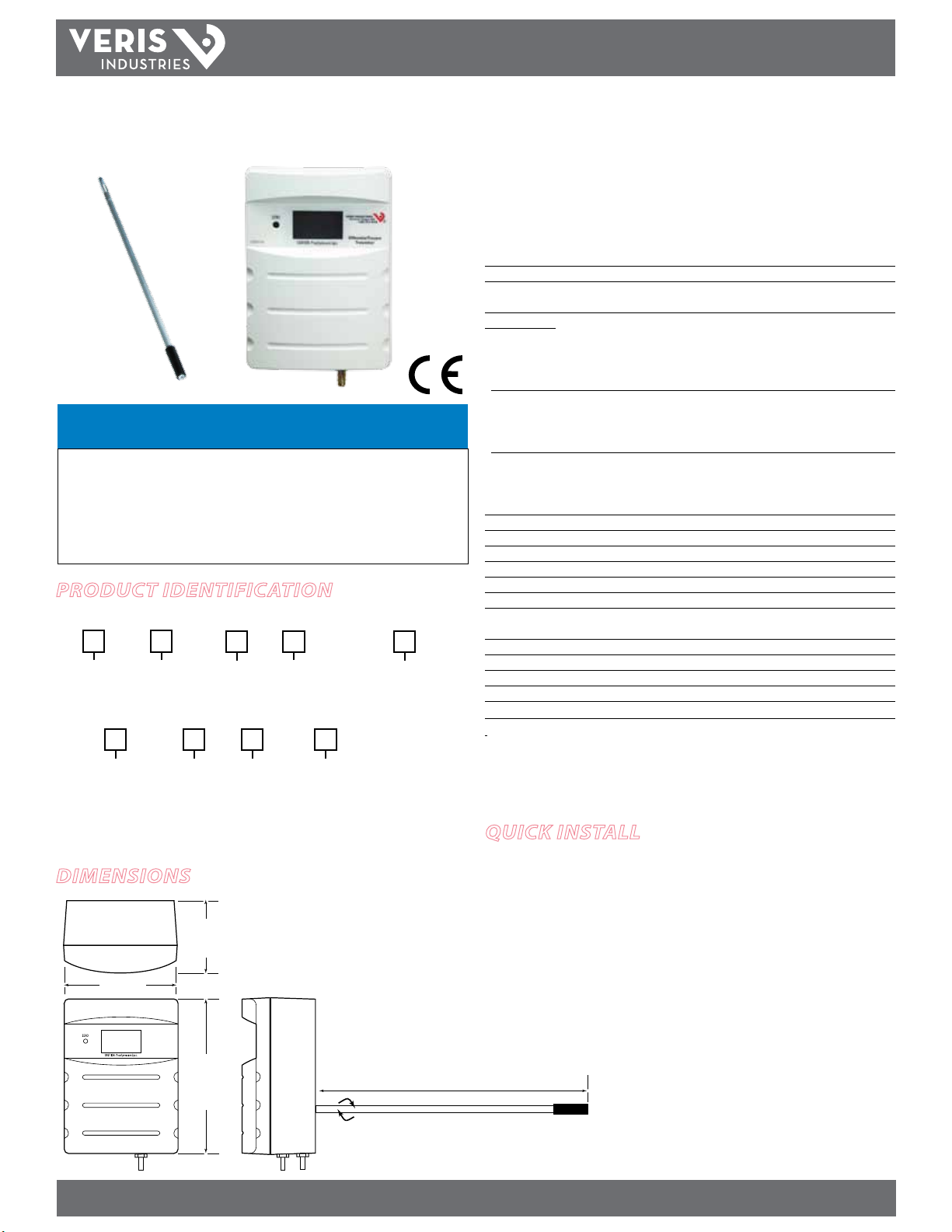
ProDuct iDentification
EnvironmEntal SEnSorS
Enclosure
PX
D = Duct
P = Panel
Local Display
PXU
Local Display
L = LCD Display
X = No Display
L = LCD Display
X = No Display
NIST
N = NIST
X = None
NIST
N = NIST
X = None
Range
01 = 0-1"W.C./0-250Pa
02 = 0-10"W.C./0-2.500kPa
Range
05
= 0-10”/0-2.500kPa
Response
S = Selectable
F = Selectable
Response
S
= Selectable
inStallation GUiDE
Digital Pressure Transducer
Dry Media
Installer’s Specifications
Media Compatibilit y Dry air or inert gas
Input Power 12-30VDC, or 24VAC nominal; 2-wire: 20mA max.; 3-wire: 30mA max.
Output Field-selectable: 2-wire, loop-powered 4-20mA
(DC only, clipped and capped), or 3-wire 0 -5V/0-10V*
Pressure Rang es:
PX: 01 Unidirec tional: 0.1/0.25/0.5/1.0” W.C. F.S., switch selectable
Bidirectional: ±0.1/±0.25/±0.5/±1.0” W.C. F.S., switch selec table
Unidirectional: 25 Pa/50 Pa/100 Pa/250 Pa, F.S., switch sele ctable
Bidirectional: ±25 Pa/±50 Pa/±100 Pa/±250 Pa, F.S., switch selectable
PX: 02 Unidirec tional: 1.0/2.5/5.0/10” W.C. F.S., switch selec table
Bidirectional: ±1.0/±2.5/±5.0/±10” W.C. F.S., switch selectable
Unidirectional: 0.250 kPa/0.500 kPa/1.000 kPa/2.500 kPa, F.S., switch sele ctable
Bidirectional: ±0.250 kPa/±0.500 kPa/±1.000 kPa/±2.500 kPa, F.S., switch select able
PXU: 05 Unidirec tional: 0.1/0.25/0.5/1.0/2.5/5/10” W.C. F.S., switch selec table
Bidirectional: ±0.1/0.25/0.5/1.0/2.5/5/10” W.C. F.S., switch selectable
Unidirectional: 25Pa/50Pa/100Pa/250Pa/0.5kPa/1kPa/2.5kPa F.S., switch selectable
Bidirectional: ±25Pa/50Pa/100Pa/250Pa/0.5kPa/1kPa/2.5kPa F.S., switch selectable
Response Time Standard: T95 in 20 sec , Fast: T95 in 2 sec, jumper selec table
Mode Unidirectional or bidirectional, jumper selectable
Display (option) Signed 3-1/2 digit LCD, indicates pressure, overrange indicator
Proof Pressure 3 psid (20.6kPa)
Burst Pressure 5 psid (34.5kPa)
Accuracy ±1% F.S. of selected range (combined linearit y and hysteresis)
Temperature Eect 1” (250Pa) models: 0.05%/°C; 10” (2.5kPa) models: 0.01%/°C
(Relative to 25°C) 0° to 50°C (32° to 122°F)
Zero Drif t (1-year) 1” (250Pa) models: 2.0% max.; 10” (2.5kPa) models: 0.5% max.
Zero Adjust Pushbutton auto-zero and digital input (2-pos terminal block)
Operating Environment 0°- 60°C (32° to 140°F); 0 to 90 % RH non-condensing
Fittings Brass barb; 0.24” (6.1mm) o.d.
Physical UL 94 V-O Fire Retardant ABS
EMC Conformance: EN 61000- 6-3:2007 and A1:2011 Class B, EN 61000-6-1:2007
EMC Special Note: Connect this produc t to a DC distribution network or an AC/DC powe r adaptor
with proper surge protection (EN 61000-6-1:2007 specication requirements).
* Minimum input voltage for 4 -20 mA operation: 250 Ω loop = 13 VDC; 500 Ω loop = 19 VDC
quick install
Dimensions
1. Plan the installation. Panel or duct mount?
2. For duct mounting, thread the probe into the rear of the device housing.
2.2"
(55 mm)
3.3"
(84 mm)
Inch H2O
Differential Pressure
Transmitter
4.5"
(114 mm)
8.0"
(202 mm)
Z103591-0A
Z205213-0D PAGE 1 ©2012 Veris Industries USA 800.354.8556 or +1.503.598.4564 / support@veris.com 07122
Alta Labs, Enercep t, Enspector, Hawkeye, Trustat, Veris, and the Veris ‘ V’ logo are trademark s or registered tradema rks of Veris Industries, L.L .C. in the USA and /or other count ries.
3. Congure the internal tubing for the selected installation method.
4. Mount the housing vertically.
5. Attach pilot tubing.
Page 2
TM
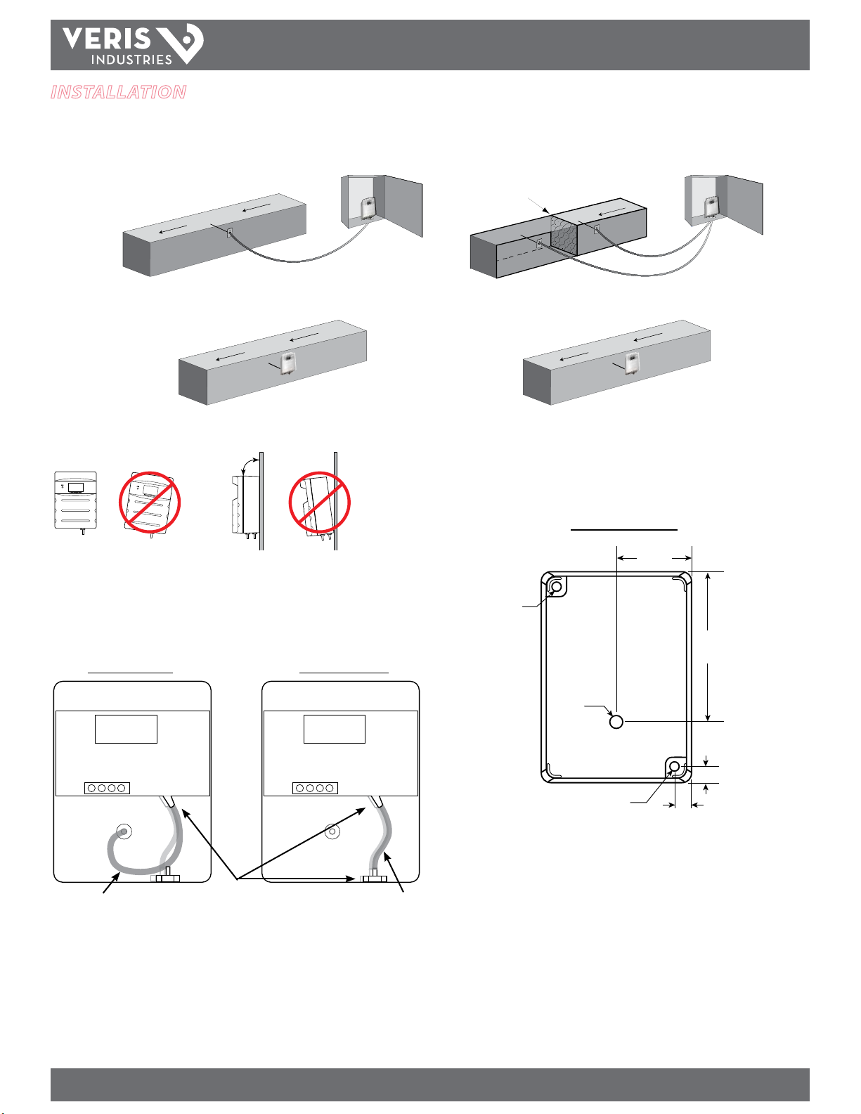
installation
1. Plan the installation. Panel or duct mount?
Static Pressure Differential Pressure
Panel
Installations
Duct
Installations
AIR FLOW
AIR FLOW
PX SEriES
inStallation GUiDE
FILTER
AIR FLOW
HIGH
LOW
AIR FLOW
90˚
Inch H2O
Differential Pressure
Transmitter
Z103591-0A
Inch H
O
2
Z103591-0A
Differential Pressure
Transmitter
YES!
YES!
2. For duct mount applications, thread the probe into the back of the device housing.
3. Congure the internal tubing for the selected installation method as shown below.
Use the larger diameter tubing for the duct mount conguration.
Tubing for Duct Mount Tubing for Panel Mount
4. Mount the transducer (see the screw hole diagram). Position the transducer
vertically.
Screw Hole Mounting
Ø 1.6 “
(40 mm)
Ø 0.15 “
(3.7 mm)
Ø 3.3 “
(83 mm)
Ø 0.2 “
(5.2 mm)
+
Ø 0.15 “
(3.7 mm)
+
Ø 0.38 “
(9.7 mm)
Ø 0.38 “
(9.7 mm)
5. Determine the length of pilot tubing needed.
Larger diameter tube
for duct conguration
Use the
front barb
Smaller diameter tube
for panel conguration
Z205213-0D PAGE 2 ©2012 Veris Industries USA 800.354.8556 or +1.503.598.4564 / support@veris.com 07122
Alta Labs, Enercep t, Enspector, Hawkeye, Trustat, Veris, and the Veris ‘ V’ logo are trademark s or registered tradema rks of Veris Industries, L.L .C. in the USA and /or other count ries.
Page 3
TM
PX SEriES
inStallation GUiDE
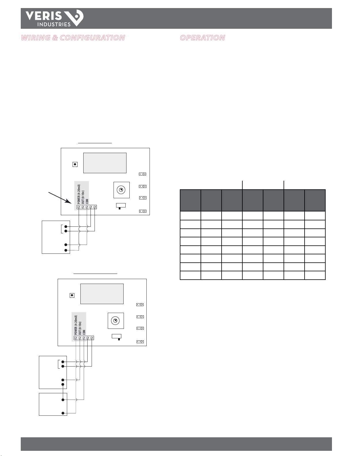
WirinG & confiGuration
Connect the transmitter to the control system and power supply as indicated below.
Optional: Connect the ZERO terminals to the digital output (contact closure) of the
control system.
Use the switch to select voltage (V) or current (mA) mode.
Jumper JP4: select 0-10 V or 0-5 V output span (voltage mode only).
Jumper JP5: select bidirectional or unidirectional mode.
Jumper JP7: select inches W.C. or Pascal scale
Jumper JP8: select fast or standard response time.
Align the arrow (not the slot) on the rotary switch to the desired full-scale range. LCD
models momentarily indicate the selected range.
2-wire, 4-20 mA
ZERO
WARNING:
Do not
apply power
to output terminal!
Permanent damage
will result.
Digital
Output
DIGITAL CONTROL
Return
POWER (4-20mA)
OUT (0-10v)
V+
3-wire, 0-5 V/0-10 V
1.000
ZERO
COM
mA
7
6
5
OUTPUT
RESPONSE
FAST/STD
JP8
UNITS
IN W.C./PA
0
1
JP7
2
MODE
3
4
BI/UNI
JP5
VOLT
5V/10V
Volt
JP4
oPeration
PX Series devices employ ceramic capacitive sensors and sophisticated temperature
compensation circuitry. The sensor achieves its best accuracy af ter an initial warm-up
period. During the rst few minutes of operation, readings at zero pressure and the
lowest pressure ranges appear erroneous. Following this initial warm-up period, PX
Series maintains its specied accuracy and stability.
LCD DISPL AY: The display momentarily indicates range “SET” when selec tion is made.
Pressure is normally indic ated on the display. Units are in inches water column (in. W.C.),
Pascals (Pa) or kilopascals (kPa) as indicated on the display. The display shows OVER
when the pressure is over range.
ZERO: Press and hold the ZERO pushbutton for 2 seconds or provide contact closure
on ‘AUX ZERO’ terminal to automatically reset the output and display to zero
pressure. To protect the unit from accidental zero, this feature is enabled only when
the detected pressure is within about 0.1 in. W.C. (25 Pa) of factory calibration.
Range Selection Guide
PX01 PX02 PX05
Rotary
Switch
Position
0 0.1 25 1 250 0.1 25
1 0.25 50 1 250 0.25 50
2 0.5 100 1 250 0.5 100
3 1 250 1 250 1 250
4 1 250 2.5 0.5 kPa 2.5 0.5 kPa
5 1 250 5 1 kPa 5 1 kPa
6 1 250 10 2.5 kPa 10 2.5 kPa
7 1 250 10 2.5 kPa 10 2.5 kPa
Inches
W.C.
Pascal
Inches
W.C.
Pascal
Inches
W.C.
Pascal
ZERO
RESPONSE
FAST/STD
JP8
UNITS
IN W.C./PA
1
JP7
2
3
4
MODE
BI/UNI
JP5
VOLT
5V/10V
Volt
JP4
Digital
Output
DIGITAL CONTROL
V IN
POWER SOURCE
24VAC/DC
1.000
0
7
6
5
ZERO
POWER (4-20mA)
OUT (0-10v)
COM
mA
OUTPUT
-
-
+
Z205213-0D PAGE 3 ©2012 Veris Industries USA 800.354.8556 or +1.503.598.4564 / support@veris.com 07122
Alta Labs, Enercep t, Enspector, Hawkeye, Trustat, Veris, and the Veris ‘ V’ logo are trademark s or registered tradema rks of Veris Industries, L.L .C. in the USA and /or other count ries.
 Loading...