

Page 1
Pub.# OM17-PRC
Operating Instruction Manual
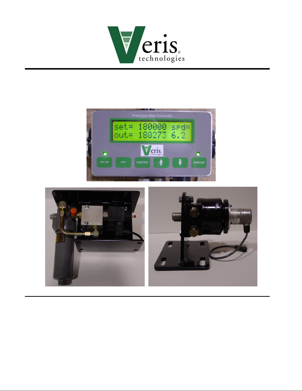
Precision Rate Controller
Veris Technologies
601 N. Broadway
Salina KS 67401
(785) 825-1978
www.veristech.com
Page 2

Pub.# OM17-PRC
WARNING !
Return all hydraulic valves to neutral position before
exiting tractor cab. Inadvertent drive rotation could
cause serious injury.
WARNING!
Escaping fluid under pressure can have sufficient
pressure to penetrate the skin. Check all hydraulic
lines and fittings before applying pressure. Fluid
escaping from a very small hole can be almost
invisible. Use paper or cardboard, not body parts,
and wear heavy gloves to check for suspected leaks.
If injured, seek medical assistance from a doctor that
is familiar with this type of injury. Foreign fluids in the
tissue must be surgically removed within a few hours
or gangrene will result.
NOTICE !
Do not weld on drill unless electronic components
are removed.
Table of Contents
Operational Requirements—Hydraulic and Electrical 1-1
Tractor Hookup 1-2
Console Functions 1-3
Rate Calibration 2-1
Speed Calibration 3-1
Operations 4-1
Varying Rates with Pre-set Function 5-1
Varying Rates with GPS-based maps 6-1
Maintenance 7-1
Troubleshooting 8-1
Important Information
!
Page 3

Operating Instructions
Drive Operational Requirements:
Hydraulic System:
Closed center, pressure compensated or load
sensed systems only
Drive will not operate on open-centered
hydraulic systems
Minimum Hyd. Pressure: 2250 psi
Maximum Hyd. Pressure: 3000 psi
Maximum Required Flow: 8.5 gpm
Electrical System:
Voltage: 12 volt DC
Amperage: 4 amperes
Tractor Hookup
Hydraulics:
1) Connect pressure hose (P) to retraction outlet
2) Connect motor return hose (T) to motor return port (if available) or to
extension outlet.
3) Set flow rate at maximum.
4) If tractor is equipped with electro-hydraulic valves, set timer to “constant” flow.
Electrical:
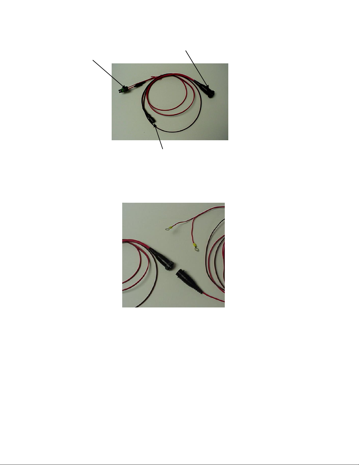
1) Power can be connected in two different manners:
a) Power port adaptor (PN 19676)
1-1
Page 4
Pub.# OM17-PRC
1-2
Connect to power port
Connect to console
Connect to power wire from implement
Figure 1
b) To battery. Make sure that eyelets are properly connected (red to positive,
Black to negative). Connect female socket to power port adapter.
Figure 2
Page 5
Pub.# OM17-PRC
1-3
On/VR key—turns
drive system on.
Press twice for VR
mode. Note:
Engage key must
also be pressed to
start drive
operation.
Function
key: used in
calibration
mode and to
program
Console for
VR recipes.
Up/down arrow
keys: used to
change rates
manually, to set
calibration
numbers, and VR
controller options.
Engage key:
press to start
drive. Note: drive
will not run
unless light
above key is
illuminated
Off key:
used to
shut off
Console.
Console Functions
Shown below in Figure 3 is the Precision Population Controller Console. The
uses of each key are as follows:
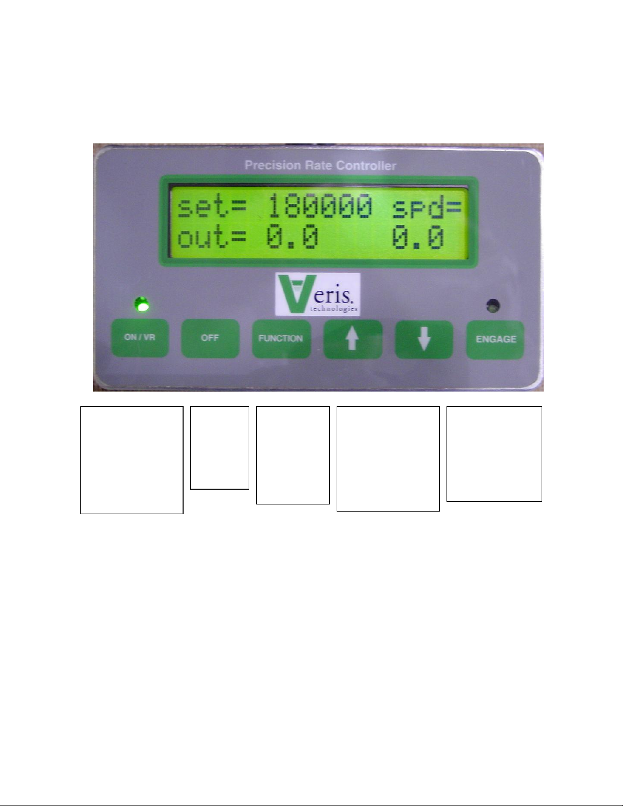
Figure 3. Console Set to Main Operating Screen, in manual mode
Page 6
Pub.# OM17-PRC
2-1
Calibration--Rate
Turn on Controller Console by pressing On/VR key. Green light above On/VR
key will illuminate when power is on. Adjust desired planting rate by using the
Up/Down arrow keys to change the Set rate. (See Figure 4)
Figure 4. Set the desired Rate by using the Up/Down arrow keys.
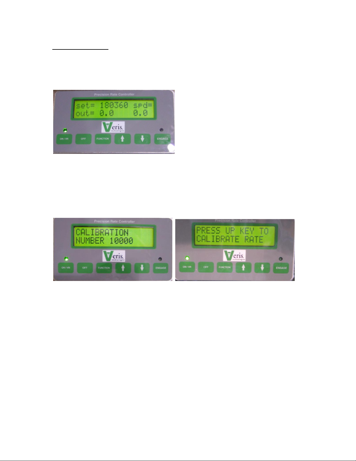
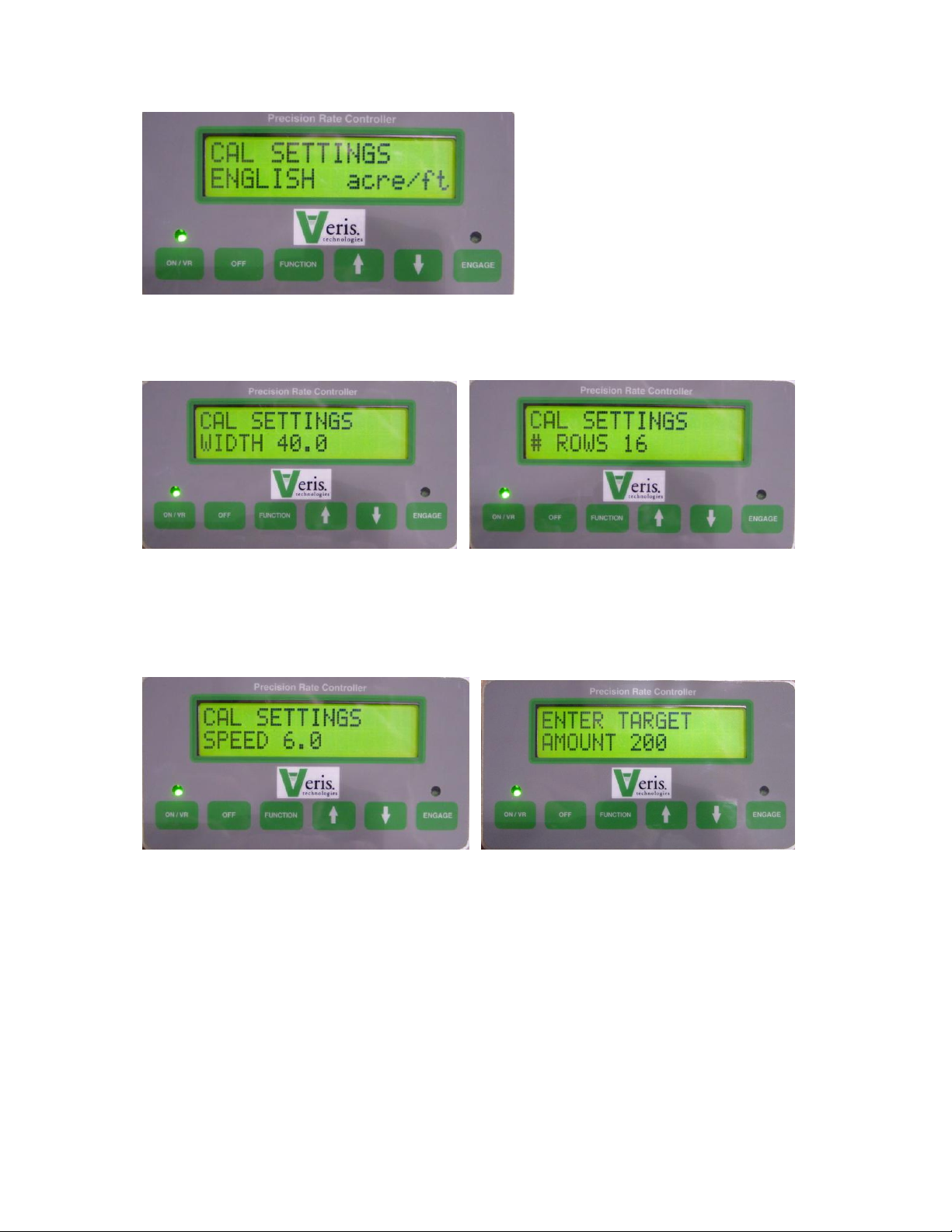
Press Function key until Calibration Number window appears. (See Figure 5)
Select drive calibration number from chart if available. If calibration number is
not known, enter 1000. Use Up/Down arrow keys to set Calibration number.
Press Function key until the Calibration window appears as shown in Figure 5.
Figure 5. Example of calibration number. Enter new calibration number using
Up/Down arrow keys. Press Function key to advance to Calibration Mode.
Figure 6. Rate calibration window. Press up arrow key to enter calibration
mode.
Page 7
Pub.# OM17-PRC
2-2
Figure 7. This is the first window that appears in Calibration mode. Press
Function key to accept, or Up key to change to metric settings.
Figure 8. Enter implement width here using Up/Down arrow keys. Press
Function key to advance to next window.
Figure 9. Enter number of rows here using Up/Down arrow keys. Press Function
key to advance to next window.
Figure 10. Enter your planned planting speed using Up/Down arrow keys.
Calibration mode will not accept a speed higher than 10 mph. Press Function
key to advance to next window.
Figure 11. Enter the number of seeds you want to count. For singulated
metering, at least 100 seeds should be selected. Press Function key to advance
to next window.
Page 8
Pub.# OM17-PRC
2-3
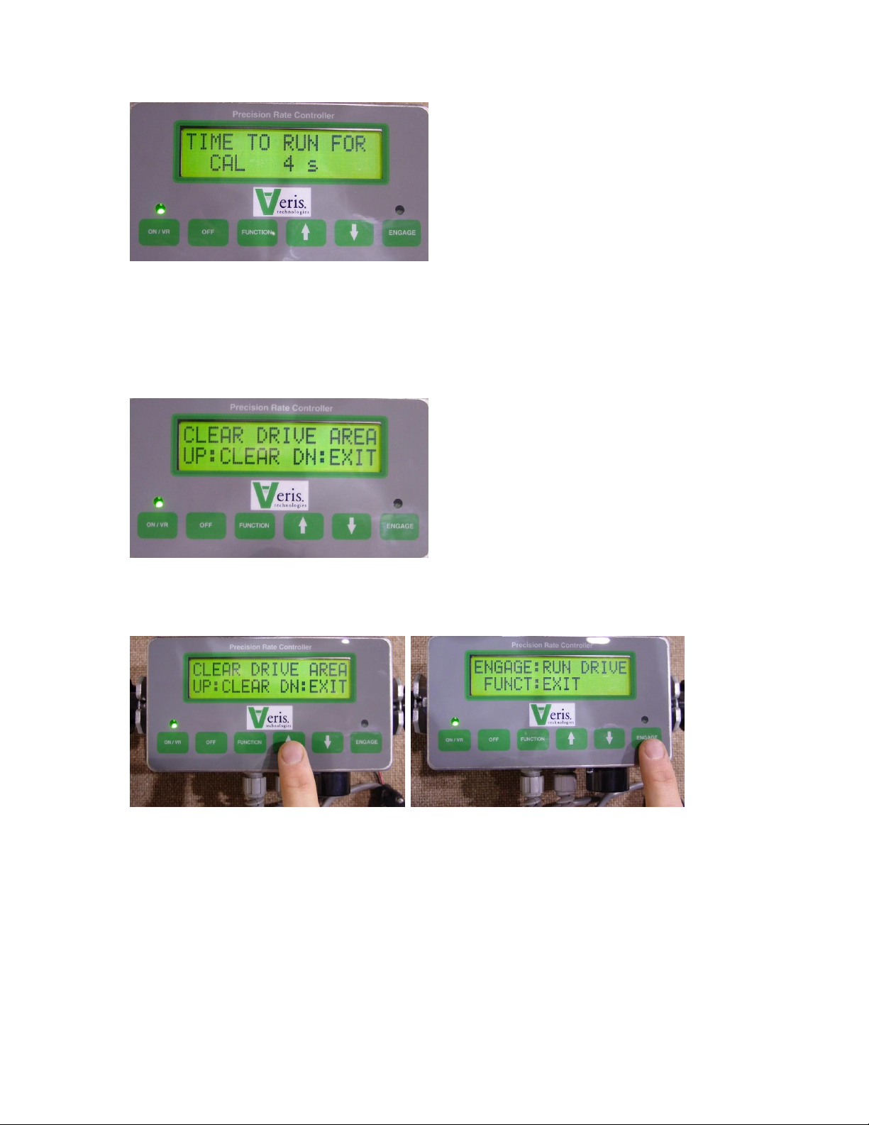
Figure 12. The cab console is informing you the length of time that the drive will
be operating, in order to meter the amount of seed you have requested, at the
calibration number, planter or application width, and number of rows you have
selected. If the screen reads TIME TOO LOW, you will need to increase the
amount of seed that you will count or measure. Press Function key to advance
to next window.
Figure 13. WARNING: The drive is about to operate, meaning there is a
danger of entanglement if anyone is in the drive area. Be sure to verify that
no one is in or near the drive area before advancing to the next step.
Figure 14. Only after you have verified the drive area is clear, press the up arrow
key to initiate calibration mode. If drive area isn’t clear, press Down arrow key to
exit calibration mode.
Figure 15. Continuing to verify that the drive area is clear, press the Engage key
to start drive rotation. Pressing Function key will exit calibration mode.
Page 9
Pub.# OM17-PRC
2-4
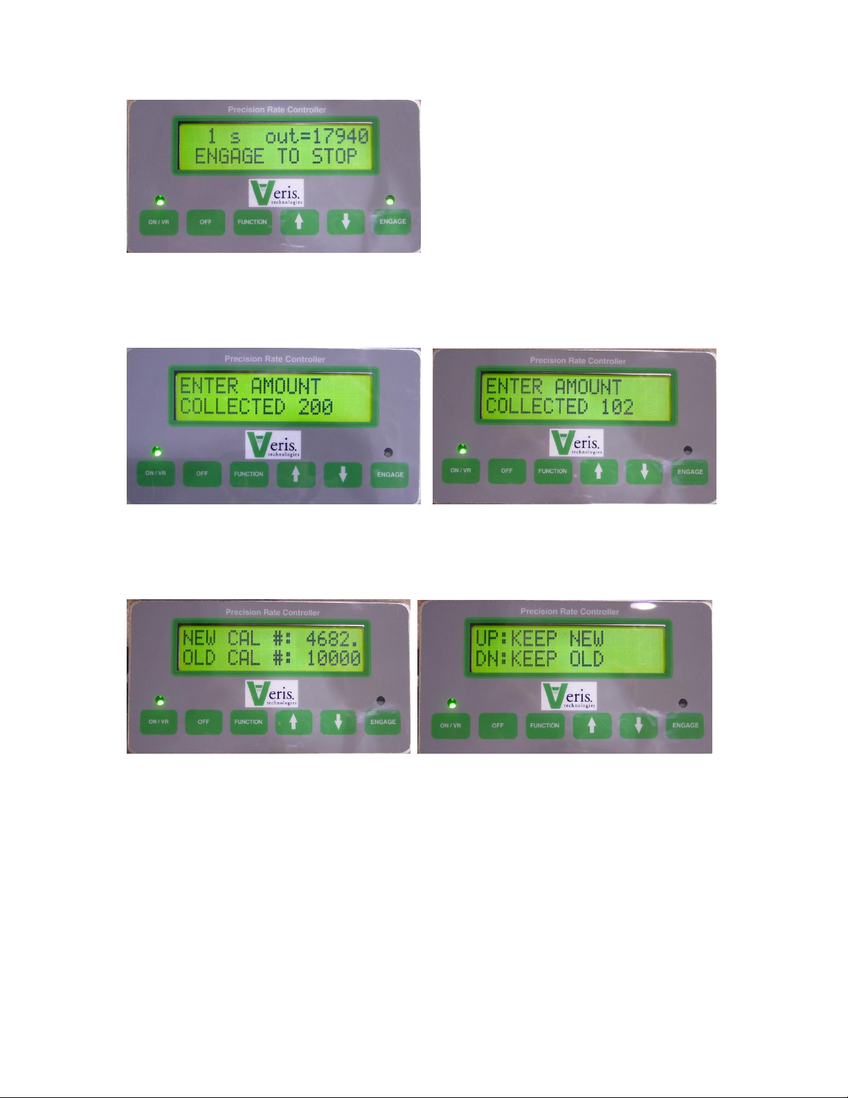
Figure 16. While the drive is rotating, the display window shows the time
remaining and the “Out” rate. CONTINUE TO MONITOR DRIVE AREA DURING
DRIVE ROTATION. PRESS THE ENGAGE KEY (OR OFF KEY) TO STOP
DRIVE DURING CALIBRATION
Figure 17. After Calibration meter rotation has ended, the screen above left will
appear. Enter the actual amount metered using the Up/Down arrow keys as
shown in Figure 18, above right. Press Function key to advance to next window.
Figure 19. A New calibration number is suggested, along with the Old calibration
number. Press Function key to advance to window shown in Figure 20.
Figure 20. If you wish to keep the Old number, perhaps to re-run the calibration
procedure, press the Down arrow key. If you want to accept the New calibration
number, press the Up arrow key.
Page 10

Pub.# OM17-PRC
2-5
Figure 21. Console window now displays the calibration number you have
selected. This returns you back to the beginning of Calibration mode as shown
in Figure 5. To re-run the Calibration procedure, follow the steps outlined above.
It is suggested that you perform the calibration mode at least twice, and
additional replications may be needed if Target and Actual amounts vary
significantly.
Page 11

Pub.# OM17-PRC
3-1
Calibration—Speed
In order for the Precision Rate Controller to meter the proper amount of material,
it must have an accurate field speed input. Speed may be supplied by radar or
by wheel pickup sensor. For the Controller to convert the pulses that it is
receiving from the speed input into accurate speed, it must be calibrated. To
calibrate the Controller for speed, press the Function key until the screen
appears, as shown in Figure 22:
Figure 22. Speed calibration screen
Figure 23. Press up to initiate new speed calibration routine; press down to
restore factory default settings.
Set two flags 400’ apart (100 meters if in metric mode). Begin driving at a normal
field speed; when the tractor passes the first flag, press engage (Figure 24). The
display will show the distance traveled. (Figure 25)
Page 12

Pub.# OM17-PRC
3-2
Figure 24 and 25.
When the tractor passes the second flag, press engage again. (Figure 26) The
display will show the error or difference between the traveled distance and the
distance calculated by the Controller. (Figure 27)
Figures 26 and 27.
If this is the first time the unit has been calibrated, this error can be large. Accept
the new speed calibration and re-run the course. Re-calibrate until the error is
within 5%. The cab console will give you the option each time you calibrate of
accepting the new settings, or keeping the previous settings. (Figure 28)
Figure 28
Page 13

Pub.# OM17-PRC
4-1
Field Operations
1. Once calibration procedure above has been followed, Console will store the
calibration and rate information until new information has been entered.
2. Turn on Controller Console by pressing the On/VR key. Green light above
On/VR key will illuminate when power is on. Pressing the On/VR key twice
will put the unit in VR mode. (See Figure 29) VR will appear on the screen
along with the Rate that is being sent from the computer. Press On/VR key
again to toggle back to manual mode. (All mode and rate changes take effect
with the release of the key.)
Figure 29. Main Operating Screen Set on VR mode
3. To change rates manually whether in manual or in VR mode, simply touch the
Up/Down arrow keys. This will change the Controller to the rate you select
manually. To return to VR, simply touch the On/VR key to toggle back to VR
mode.
4. Engage the hydraulic flow by pushing FORWARD on the tractor remote
hydraulic lever. The remote lever must be LOCKED OPEN in this position to
provide constant flow to the drive motor.
-- John Deere tractors with Sound-Gard body: Use lever lock clip
to lock lever foward. See your dealer for lock purchase and installation.
-- John Deere 7000 series tractors: Rotate valve detent selector to
motor position to lock lever in forward position.
-- John Deere 8000 series tractors: Set timer to continuous. Push
forward until detent clicks.
--Case –IH Magnum tractors: Lock lever in forward detent position.
You may need to turn up detent pressure to maximum setting. Do
not tie hydraulic lever past detent position with a tarp strap. See
your dealer for details.
-- Other tractors: Lock lever in forward detent position. See your
dealer for proper instructions for motor control.
Page 14

Pub.# OM17-PRC
4-2
5. Press Engage key to activate drive. Green light above Engage key will
illuminate. After 20 seconds of no speed signal, drive will disengage. This is
to help prevent inadvertent entanglement in planter drive mechanism. To
restart drive after it has disengaged, press Engage key.
6. The Console display shows two numbers while operating: “Set” rate is the
rate you tell the system to plant, and the “Out” rate is the calculated rate
based on the actual rotations of the drive. The “Out” reading is monitoring
the drive system; it isn’t monitoring population. It verifies that the drive
system is functioning properly. Note: The “Out” readings will normally
fluctuate within 5% of the “Set” rates. This fluctuation is evidence of the drive
system compensating for minor fluctuations in ground speed.
7. If “Out” rate varies from the “Set” rate by more than 20%, an audible alarm will
sound.
8. If Controller is powered directly from the battery or via un-switched power
port, make sure to power Console off when tractor is shut down, in order to
prevent tractor battery drain.
Page 15

Pub.# OM17-PRC
5-1
Varying Rates with Pre-set Function
The Veris Precision Rate Controller allows you to pre-set three different rates,
and then change rates on-the-go by toggling from one rate to another rates with
the Up or Down arrow keys. To enter the three pre-set rates, press Function key
until Pre-set Menu screen appears: (Figure 30) Use Up-Down arrow keys to
toggle from manual mode to pre-set mode.
Figure 30
Press Function key to move to the next pre-set screen, and the Up-Down arrow
keys to set the pre-set rates. (Figure 31)
Figure 31.
When in Pre-Set mode, the main operating screen shows the pre-set rate
currently being applied. (Figure 32) Note: when you are in Pre-set mode, the UpDown arrow keys only toggle between pre-set rates.
Figure 32. Operating screen when using Pre-set Rates.
Page 16

Pub.# OM17-PRC
6-1
Varying Rates with GPS-Based Maps
Settings for FarmWorks SiteMate used with Veris Precision Rate Controllers—
QUICK REFERENCE GUIDE
(Create a .shp recipe file in FarmWorks Site Pro, SMS 2.0, SSToolbox, or other
software that will create a .shp file, and transfer it to SiteMate.)
SiteMate Settings: (version 8.12)
1. Select CONFIGURE Tab. Select SETTINGS. Select VARIABLE RATE
SETUP. Select NEW. Type in GP PPC. Under CONTROLLER TYPE, select
Rawson from the scroll-down list. Under COMM PORT select the port
number for the serial card or flash jacket port.
2. Select MAP tab. Enter DEFAULT rate. This will be the rate that SiteMate will
call for if GPS signal is lost or you are outside the map area. Note: if GPS
signal is interrupted, or if you are outside the map area, GP Controller will
continue applying rate it was set at when signal was interrupted, until signal is
regained, or another rate is set manually. If power to the SiteMate is
interrupted, you will need to restart the recipe to return to VR. In the
CONVERSION window, enter the conversion rate as follows: if your recipe
(.shp file) is written using the entire number as the desired rate, i.e. 30,000
seeds/acre on the recipe means 30,000 seeds/acre is the desired rate, enter
both the Map Unit and Controller Unit as 1. If the recipe is written using a
different number, i.e. 30 on the recipe means a population of 30,000, then you
will need to enter the conversion multiple—in that case 1 Map Unit = 1,000
Controller Units.
3. Under the APP tab, enter the Feed Delay as 3 seconds. Enter the Following
Distance (the offset from the planter meters from the GPS) in the Following
Distance window. Enter the Swath Width of your implement.
4. Under the CTRL tab, enter the Nominal Rate as follows: Divide the highest
rate on your recipe by 1.6. This is your Nominal rate. For example, if your
highest rate is 200,000 the nominal is 125,000. If your highest rate is 32, your
nominal rate is 20. Enter the Step as 4%. Exit VRA Controller Setup by
clicking OK button to save the settings.
5. Under FILE, Open VRT and select the Rx Map (recipe) for the field. Press
the SETUP button and select the controller option that you have set up using
these Settings Instructions.
6. Press GO. The Rx rate window shows the rate that is being sent to the Veris
Precision Rate Controller. The APPLIED window shows the rate that the Veris
Controller is applying.
Page 17

Pub.# OM17-PRC
6-2
Settings for Veris Precision Rate Controllers:
1. Connect SiteMate computer to Cab Console using 9-pin serial cable, as shown in
Figure 23.
2. Set Calibration Number as described on pages 6-10
3. Press Function key and go to Rawson mode. Press Function key until the
Nominal Rate appears on the display. Using the Up/Down arrow keys, set the
Nominal Rate to the same number as you entered in the SiteMate program in
step 4 above. Once Nominal Rate is set, press Function key until the main
operating screen appears, as shown in Figure 3.
4. Press On/VR key again to toggle to VR mode. VR should appear on the screen
along with the Rate that is being sent from the SiteMate computer. Verify that the
rate shown on the Cab Console is the same as the recipe sent from SiteMate.
Press Engage key to activate the Precision Rate Controller.
5. To change rates manually when in VR mode, simply touch the Up/Down arrow
keys. This will change the Controller to the rate you select manually. To return to
VR, simply touch the On/VR key to toggle back to VR mode.
Troubleshooting GPS-based Seeding with SiteMate
1. No Rx rate appears on SiteMate
-has field been selected? Select VRT file (see SiteMate Settings, Step 5)
-check recipe to verify that it is valid by viewing Attributes for each zone in
SiteMate
-if recipe calls for zero rate as the default, do you have GPS signal, or are you
outside of field?
2. Rx rate appears on SiteMate, but no Applied Rate.
-make sure “Go” button on SiteMate is pressed. (button should read “Stop” when
recipe is being sent to Cab Console)
-you must be planting in order for Applied Rate to appear.
3. Rx rate appears on SiteMate but not on Cab Console.
-make sure Cab Console is set to VR Mode (Figure 29)
-double-check all cable connections
-check Nominal rates on both the SiteMate (SiteMate Settings, Step 4), and on
the Cab Console (Veris Controller Settings, Step 3) These must be set to the
same number.
4. Rates on Veris Cab Console and on SiteMate do not match.
-check Nominal rates on both the SiteMate (SiteMate Settings, Step 4), and on
the Cab Console (Veris Settings, Step 3) These must be set to the same
number.
-Re-check calibration number, and re-run calibration procedure if necessary
-The recipe rates from SiteMate are in 4% increments. If the two rates are within
this 4% range, the units are operating normally.
-Check the Conversion number (SiteMate Settings, Step 2). If the recipe
requires a target conversion number, i.e. the recipe is for 25 which means 25,000
seeds/acre, the target conversion number will be 1000. In this case the Nominal
Rate in SiteMate and the Veris Console should be near 25,000. See SiteMate
Settings, Step 4 for calculating Nominal Rate.
Page 18

Pub.# OM17-PRC
6-3
9 pin
serial
cable for
recipes
Population Monitor rate does not match Veris Console.
-Make certain that SiteMate and Console agree. If not, see Troubleshooting
step 4 above.
-Re-check GP calibration number, with metering wheel and row spacing.
-Re-check planter monitor settings: calibration number, row spacing, number
of rows, swath width, seed, etc.
-On small seeds and/or high rates, if population monitor consistently indicates
a lower population than the Cab Console, contact monitor manufacturer for
performance specs for that application.
5. GPS signal is not being received by SiteMate:
-verify that GPS serial port (which is also the docking port) is not set to PC
connection only (Start/Settings/Communications/PC Connections
-check GPS settings in Configure/Settings/GPS settings/COM (typically
COM1, 4800 Baud, 8 data bits, Parity None, and Stop Bits 1)
-Click Data tab to view GPS details
Figure 33.
Settings for Ag Leader PF3000 Monitors used with Veris Precision Rate
Controllers—QUICK REFERENCE GUIDE
(Create a .tgt recipe file in SMS 2.0 or FarmWorks Site Pro, or other software
that will create a .tgt file, and copy it to an SRAM or Flash card that is compatible
with the PF 3000.)
Page 19

Pub.# OM17-PRC
6-4
PF3000 Settings:
1. Press SETUP key. Press SWATH key. Set swath to that of your implement
2. Press SETUP key. Press VEHICLE key. Set Primary speed sensor to GPS.
3. Press SETUP key. Press CARD key. Set the following:
Log Device: None.
4. Press SETUP key. Press APP RATE key. Set the following:
Application Control: On
Look Ahead: On
Current target file: press Edit to view the files you have on the card; select the
one you wish to use.
5. Press SETUP key. Press CONTROLLER key. Select controller as Rawson
Accu-Rate. Press EDIT SETTINGS. Set the following:
Number of pulses/10 revolutions: 500
Nominal rate: Divide the highest rate on your recipe by 1.6. This is your
Nominal rate. For example, if your highest rate is 200,000 the nominal is
125,000. If your highest rate is 32, your nominal rate is 20.
Percent rate change: set to 4%
Area count: Set to Standard
Stop height: Set to 8
Act. rate recording method: Set to Sensor
Controller time delay: Set to 4 sec
Application offset from GPS: Enter the distance from the row unit to your GPS
location.
Serial Port: Port 3
6. Press SETUP key. Press PRODUCT key. Select product and press EDIT
SETTINGS. Set the following:
Controller Device: Rawson Accu-Rate
Cal. number for act. rate: set to 0
Actual Rate Scale Factor: Set to 1.000
Target Rate Units: Set to Seeds
Actual Rate Units: Set to Seeds
Target conversion Number: If your recipe (.tgt file) is written using the entire
number as the desired rate., i.e. 30,000 seeds/acre on the recipe means
30,000 seeds/acre is the desired rate, enter a 1.000. If the recipe is written
using a different number, i.e. 30 on the recipe means a population of 30,000,
then you will need to enter the conversion multiple—in that case 1,000.
Target Rate increment: Determines the increment value by which you can
change the manual target rate with each press of the arrow keys.
7. Press FIELD key. Set Field. Set Product (press key to right of product)
Page 20

Pub.# OM17-PRC
6-5
Settings for Veris Precision Rate Controllers:
1. Connect PF3000 to Console using 9 pin serial cable as shown in Figure 33.
2. Set Calibration Number as described on pages 6-10.
3. Press Function key and go to Rawson mode. Press Function key until the
Nominal Rate appears on the display. Using the Up/Down arrow keys, set
the Nominal Rate to the same number as you set the PF3000 in step 5
above. Once Nominal Rate is set, press Function key until the main
operating screen appears, as shown in Figure 3.
4. Press On/VR key again to toggle to VR mode. VR should appear on the
screen along with the Rate that is being sent from the PF3000. Verify that the
rate shown on the Cab Console is the same as the recipe sent from the
PF3000. Press Engage key to activate the Veris Precision Rate Controller.
5. To change rates manually when in VR mode, simply touch the Up/Down
arrow keys. This will change the Controller to the rate you select manually. To
return to VR, simply touch the On/VR key to toggle back to VR mode.
Troubleshooting GPS-based seeding with PF3000
1. No Target Rate appears on the PF3000
-has field been selected? Select target file (see PF3000 Settings, Step 4)
-check recipe to verify that it is valid
-if recipe calls for zero rate as the default, do you have GPS signal, or are you
outside of field?
2. No Actual Rate appears on the PF3000.
-actual rate cannot be logged using the PF3000 with the Veris Precision Rate
Controller
3. Target Rate appears on PF3000 but not on Cab Console.
-make sure Cab Console is set to VR Mode
-double-check all cable connections
-check Nominal rates on both the PF3000 (PF3000 Settings, Step 5), and on
the Cab Console (Veris Console Settings, Step 3) These must be set to the
same number.
9. Rates on Veris Cab Console and on PF3000 do not match.
-check Nominal rates on both the PF3000 (PF3000 Settings, Step 5), and on
the Cab Console (Veris Settings, Step 2) These must be set to the same
number.
-Re-check calibration number, and re-run calibration procedure if necessary
-The recipe rates from the PF3000 are in 4% increments. If the two rates are
within this 4% range, the units are operating normally.
-Check the target conversion number (PF3000 Settings, Step 6). If the recipe
requires a target conversion number, i.e. the recipe is for 25 which means
25,000 seeds/acre, the target conversion number will be 1000. In this case
the Nominal Rate on the PF3000 and on the Veris Console should be near
25,000. See PF 3000 Settings, Step 5 for calculating Nominal Rate.
Page 21

Pub.# OM17-PRC
6-6
10. Population Monitor rate does not match Veris Console.
-Make certain that PF3000 and Veris Console agree. If not, see
Troubleshooting step 3 above.
-Re-check calibration number, and re-run calibration procedure if necessary
-Re-check planter monitor settings: calibration number, row spacing, number
of rows, swath width, seed, etc.
-When planting small size seeds and/or at high rates, if population monitor
consistently indicates a lower population than the Veris Console, contact
monitor manufacturer for performance specs for that application.
Page 22

Pub.# OM17-PRC
7-1
Pop-out
indicator
Element
Maintenance
As with any hydraulic system, contamination is the most common cause of
performance problems and pre-mature wear. Make a special effort to properly
clean quick couplers prior to attaching the hoses to tractor.
1) Filter --All fluid is filtered through the high pressure filter (PN 18574) and it will
provide protection to the hydraulic components of your drive if properly
maintained. It is equipped with a pop-out indicator to alert that the replaceable
element is clogged, and should be changed immediately if this situation occurs.
Normal service life of the element will vary based on the precautions that you
take to minimize contamination at the couplers and routine service of the tractor
filtration. (See Figures 34 and 35)
To change the element:
1) Un-screw lower canister from filter, catching and disposing of used fluid.
2) Remove and discard element.
3) Install new element (PN 19856)
4) Clean canister threads and lube o-ring with hydraulic fluid, then re-install.
5) Re-set pop-out indicator if necessary. (See Figure 35.)
It is a good idea to keep a filter element on hand, and we recommend changing
annually, and more frequently in high-acreage usage, and in conditions prone to
contamination.
Figures 34 and 35 Filter element and pop-out indicator
2) Between planting seasons, store cab console inside in a relatively stable and
dry environment.
3) Avoid direct spray from high pressure washers on the motor encoder and the
external controller box. These units are sealed from normal moisture, but
high pressure could inject water into the housing.
4) Keep electrical connects free from dirt and grease. It’s a good idea to
occasionally spray the terminals with contact cleaner to ensure proper
connection.
Page 23

Pub.# OM17-PRC
8-1
Troubleshooting
Drive will not rotate: (see Troubleshooting flow chart and electronics
overview)
1. Check cab console:
1.1) No power to cab console – check with voltmeter.
1.2) Upper line (set) is visible but no lower line (out rate and speed) on display:
move to Communication troubleshooting below
1.3) 1 or 10 amp fuse on power cable may be blown.
d) Engage button is not on – check to see if green indicator light is on.
1.4) Use Cab Console Power Tester (part # 27857) to check power out of cab
console. Install tester on round 7 pin power/com cable from cab console. Turn
drive on. Green LED shows power to external controller. Red LED shows power
to solenoid. If LED lights are not lit, double-check power and connections;
replace cab console if needed.
2. Check Communication between cab console and drive:
2.1) Check to see if power and communication cable (main harness) is properly
connected.
2.2) If no lower line on cab console appears (speed and output rate), and drive
will not rotate in calibration mode, use Cable Continuity Tester (part #27859) to
test power and communication to external controller. (WARNING: TO PREVENT
DAMAGE TO COMPONENTS, DISCONNECT POWER/COM CABLE FROM
CAB CONSOLE AND EXTERNAL CONTROLLER BEFORE INSTALLING THIS
TESTER; Install 4-PIN TEST PLUG on end of 4 pin power/com cable before
powering the Cable Continuity Tester—remove before reattaching power/com
cable directly to cab console.
2.3) (If Cable Continuity Tester shows power is getting to external controller, turn
power off and remove Cable Continuity Tester and 4 pin test plug from ends of
power/com cable. Reattach power/com cable to cab console and external
controller)
2.4) If power/com cable tester shows power and communication is reaching
external controller from cab console, and no lower line appears on cab console,
replace chip or external controller. Call Service Department
2.5) If Cable Continuity Tester (part #27859) isn’t available, check cable with
voltmeter at connection at control module.
3. Test Relay inside external controller
3.1) Use Relay Output Tester (part # 27860) to test relay inside external
controller. Install tester to weather-pak solenoid connector from external
controller. With tractor engine off, start drive calibration function. Auditory alarm
should buzz for 1.5 seconds when drive is engaged in calibration mode. If alarm
does not sound, relay or external controller may need to be replaced. Call
Service Department.
Page 24

Pub.# OM17-PRC
8-2
Rapid drive rotation
may occur and
cause serious injury.
4. Check hydraulics:
4.1) Check to see if hydraulic lever is in detent position.
4.2) Hydraulic lever is in wrong detent direction--a check valve at outlet of motor
prevents reverse rotation.
4.3) Make sure that both hoses are properly
connected to tractor remotes.
4.4) Inadequate system pressure. Place pressure
gauge at filter and check reading. If system
pressure is below tractor specifications, check
system.
4.5) Power solenoid directly: DANGER: RAPID
DRIVE ROTATION MAY OCCUR AND CAUSE
SERIOUS INJURY. KEEP CLEAR OF DRIVE AREA.
a. Disengage Hydraulics
b. Reduce flow to 30-50%
c. Power solenoid directly by connecting power weather-pack
connector to solenoid weather-pack connector. If drive doesn’t rotate,
Proportional coil (PN 19799) may be defective. Check continuity with
meter, or energize with 12v power and check for magnetic pull with small
screwdriver. Double-check connections on solenoid cable. If solenoid
energizes but drive does not rotate when powered directly, tractor
hydraulics are not properly engaged.
4.6) Excessive torque in drive system. Disconnect main drive chain to check for
rotation under zero load. Check for a problem with the mechanical portion of
drive, such as foreign material wedged in meter, frozen bearings, misaligned
chains, or swelled grain in meter. Install pressure gauge at motor inlet. Pressure
should be 1000-1500 psi. If pressure is above 2000 psi, significant torque
problems are present.
5. Check Speed signal (if drive rotates in calibration mode but not when planting)
5.1) No signal from speed sensor – check connection at sensor and at drive
controller.
5.2) Excessive gap between wheel sensor and sensor plate – re-adjust to .030
5.3) Use Speed Simulator (part #27858) to troubleshoot speed loop. Leave
tractor stationary and drive hydraulics do not need to be engaged
a) Test speed sensor and hall effect sensor; replace sensor if simulated speed
appears on cab console
b) Test speed cable between speed sensor and hall effect module; replace cable
if simulated speed appears on cab console
c) Test hall effect module and cable to external controller; replace module and
cable if simulated speed appears on cab console
If speed does not appear with speed simulator, external controller or chip may
need replacement. Call Service Department.
Page 25

Pub.# OM17-PRC
8-3
Drive rotates but not at desired speed:
6. Drive (out rate) fluctuating erratically
6.1) If indicated field speed on drive is also fluctuating erratically, trouble-shoot
speed signal loop
6.2) If field speed is steady, check for loose set screws on motor encoder,
contamination of proportional valve, or mechanical binding of chain on row unit
7. Indicated speed fluctuating erratically.
7.1) Use speed simulator to troubleshoot speed loop. Leave tractor stationary
and drive hydraulics do not need to be engaged. If steady speed between 4-10
mph appears on cab console using speed simulator, troubleshoot radar, wheel
pickup sensor, hall effect module. If steady speed does not appear with speed
simulator, external controller may need replacement. Call Service Department.
7.2) Check radar gun angle
7.3) Check gap between wheel sensor and pickup plate
7.4) Check power to system < 12 volt power will cause drive to behave
erratically—often problem manifests itself in speed loop
8. Drive shuts off while planting
8.1) If it occurs after 20 seconds of not planting, such as turning on headlands,
operation is normal safety shutoff (on units with radar speed signal)
8.2) Check setting of speed signal interrupter switch—re-position as necessary to
keep actuator from disengaging while planting
8.3) 1.5 second delay shutting off drive—causes: chain binding, inadequate
hydraulics
9. Drive will not achieve desired rate:
9.1) Re-check calibration number, and re-run calibration procedure if necessary
9.2) Check to make sure that your desired rate is within the range of the meter
that is installed.
9.3) Inadequate hydraulic flow. Adjust flow control to higher position. Check with
flow meter if flow is suspect.
9.4) Field speed too high. Check maximum planting rate in seed chart for rate
that you are planting.
9.5) Check sprocket combinations; see Assembly and Parts Manuals for the
planter you are operating (30P and 40P models)
9.6) Check speed shown on cab console against other speedometer—tractor,
planter monitor. If drive speed is significantly lower, recalibrate speed on drive.
Page 26

Pub.# OM17-PRC
8-4
10. Drive plants significantly higher than desired rate:
10.1) Re-check calibration number, and re-run calibration procedure if necessary
10.2) Ensure that you have installed the correct seed meter.
10.3) Check sprocket combinations; see Assembly and Parts Manuals for the
planter you are operating (30P and 40P models)
10.4) Check speed shown on cab console against other speedometer—tractor,
planter monitor. If drive speed is significantly higher, recalibrate speed on drive.
11. Drive continues to rotate after tractor has stopped:
Contamination or wear in proportional valve (PN 19798) Remove and inspect.
Blow out with compressed air. Check o-rings and re-install. Replace if
necessary.
12. Fluid weeping from motor shaft seal:
Excessive backpressure in return hose. Check quick coupler connection. Use
motor control port for return if available.
Page 27

Pub.# OM17-PRC
8-5
Message
Cause
Solution
COMM TIMEOUT
Power to or
communication with the
external controller was
interrupted during
calibration.
Check power and
communication
connections from the cab
console to the external
controller and re-run
calibration.
TIME OVER LIMIT
The external controller
ran too long in
calibration.
Re-run calibration. If the
same message appears,
call technical support.
USER
TERMINATED
The engage key was
pressed during
calibration.
Re-run calibration.
CALIBRATE
ERROR
The drive did not turn
when calibration began.
Check encoder cable
and connection, solenoid
cable and connection,
and hydraulic lever
position.
Calibration Troubleshooting:
13. If the time to run for calibration is less than 4 seconds, the cab console will
display TIME TOO LOW. Pressing the FUNCTION key will bring up the ENTER
TARGET AMOUNT screen. The target should be raised to increase the
calibration time. If the time is greater than 255 seconds, the cab console will
display TIME TOO HIGH. Pressing the FUNCTION key will bring up the ENTER
TARGET AMOUNT screen. The target should be lowered to decrease the
calibration time.
14. While rate calibration is running, one of four error messages may be
displayed:
Pressing FUNCTION will exit rate calibration from these error screens.
 Loading...